pii.sagepub.com. Downloaded from ... pii.sagepub.com. Downloaded from ..... 2 Tomlinson, S. P. Use of AMESim to investigate feasibility of all-electric drives for ...
Proceedings of the Institution of Mechanical Engineers, Part I: Journal of Systems and Control Engineering http://pii.sagepub.com/
A computationally efficient technique for modelling velocity-dependent sliding friction S P Tomlinson, R W Cooke and D C Cosserat Proceedings of the Institution of Mechanical Engineers, Part I: Journal of Systems and Control Engineering 2003 217: 139 DOI: 10.1177/095965180321700207 The online version of this article can be found at: http://pii.sagepub.com/content/217/2/139
Published by: http://www.sagepublications.com
On behalf of:
Institution of Mechanical Engineers
Additional services and information for Proceedings of the Institution of Mechanical Engineers, Part I: Journal of Systems and Control Engineering can be found at: Email Alerts: http://pii.sagepub.com/cgi/alerts Subscriptions: http://pii.sagepub.com/subscriptions Reprints: http://www.sagepub.com/journalsReprints.nav Permissions: http://www.sagepub.com/journalsPermissions.nav Citations: http://pii.sagepub.com/content/217/2/139.refs.html
>> Version of Record - Mar 1, 2003 What is This?
Downloaded from pii.sagepub.com by guest on September 7, 2012
139
A computationally e�cient technique for modelling velocity-dependent sliding friction S P Tomlinson*, R W Cooke and D C Cosserat QinetiQ ( Winfrith), Future Systems Technology Division, Winfrith Newburgh, Dorset, UK
Abstract: This paper contains a summary of research undertaken at QinetiQ ( Winfrith) to simulate velocity-dependent ‘stick/slip’ or ‘sliding’ friction for use in the modelling of complex engineering systems. The research arises from combined simulation and experimental investigations conducted into the performance optimization of towed array outboard handling systems on submarines and surface ships. However, the technique developed is general and suitable for any time-domain system simulation, entailing the solution of a set of non-linear di�erential equations. The actual friction– velocity relationship may be either equation based or determined from experimental data as a set of x–y values. The simulation technique is novel in that it avoids the traditional problem of a friction discontinuity as the surface relative velocity changes sign. It thereby overcomes the computational problems that often occur when multiple discontinuities are encountered, such as simulations stopping prematurely, failing or giving erroneous results. Keywords: stick/slip or sliding friction, friction and directional discontinuity, multiple discontinuity, macro-relationship, numerical e�ciency, multiple-friction systems, monotonic friction, implicit predictor–corrector method
NOTATION af f fc F c F h F , fstic s i�ag izone k m n vtol x dx /dt, v d2x /dt2, vdot t
Subscripts applied force viscous friction coe�cient sliding friction force applied bulkhead core force applied hose force stiction force integer �ag (computational ) velocity operating zone (computational ) spring rate mass number of di�erential equations velocity tolerance displacement velocity acceleration time
The MS was received on 30 July 2002 and was accepted after revision for publication on 8 January 2003. * Corresponding author: QinetiQ (Winfrith), Future Systems Technology Division, Platform and Submarine Systems, Building A22 (Room 174), Winfrith Technology Centre, Winfrith Newburgh, Dorset DT2 8XJ, UK. I04802 © IMechE 2003
0 1 2 3
1
initial state device hose bulkhead core
CHARACTERISTICS OF TOWED ACOUSTIC ARRAYS
The automatic deployment and recovery of towed acoustic arrays from submarines is a necessary requirement for military operations and must be achieved in a wellcontrolled and safe manner. Towed arrays are used to obtain sensitive intelligence information by receiving sound levels over a wide range of frequencies. It is important that the arrays, containing delicate electronic listening devices, are carefully handled to avoid damage. Thus, the array construction embodies an outer protective layer of hose made of a synthetic polymer plastic, typically polyvinyl chloride (PVC ). In a bulkhead array, an internal strength member ensures that a large tension is transmitted using a driving device (array deployer) to move the array on and o� a storage winch. An alternative Crustacean array does not use bulkheads, relying more on the outer hose for strength, but embodies the
Proc. Instn7,Mech. Downloaded from pii.sagepub.com by guest on September 2012
Engrs Vol. 217 Part I: J. Systems and Control Engineering
140
S P TOMLINSON, R W COOKE AND D C COSSERAT
same general transmission and frictional characteristics. The guidance route at the back of a submarine involves bends and changes of direction, tending to increase friction levels, resulting in compression of the array hose. If this becomes excessive, a material failure termed a ‘ruck’ occurs and a system malfunction will result. It is vital that the power system (normally electric or electrohydraulic ) controlling the array is designed optimally in order to avoid either rucking or zero tension conditions, when a large tension is required. In order to investigate the behaviour of these complex systems, it is necessary to employ computer simulation [1], and commercial packages such as AMESimTM [2] and MATLABÒ SimulinkTM [3] are becoming increasingly used for this purpose.
1.1 Frictional characteristics of acoustic arrays A bulkhead array itself comprises a sti� load bearing core and an outer hose. For simulation purposes, the load-bearing core (usually made of Kevlar) is idealized as a spring with high tensile sti�ness but which cannot support compressive loads. The hose gives physical protection to the sensitive transducers contained within it. In practice, the hose also supports a proportion of the total load in the array but, by the nature of its construction, compressive loads may occur. The schematic of Fig. 1 indicates the general construction.
1.2 The PVC hose For system simulation purposes, the portion of the array within the handling system at any time is treated as a collection of mass–spring–damper elements connected in series. The deformation of each unit is calculated as it passes through the handling system, enabling the state of the array hose at any point in time and space to be determined throughout the deployment and recovery processes.
Fig. 1
1.3 Bulkheads and end connectors A towed acoustic array is deployed and recovered via an outboard interface to the sea, due to the action of its transmission system. This exerts forces from powered devices, which are normally electrohydraulic [1 ] or electric [2]. Highly variable non-linear friction e�ects are experienced at bends, pulleys and powered devices. Figure 2 is a simpli�ed schematic of a guidance route for a towed array handling system. The friction is essentially of a stick/slip (Coulomb ) nature [4], as a result of normal forces transmitted by devices that are either passive (bends and pulleys) or active (winch and deployer drives). A small amount of viscous friction, proportional to speed, is also present. Rigid ‘bulkheads’ are distributed along the core. The purpose of the bulkheads is to prevent damage to the sensitive acoustic transducers as the array is stored on the winch, enabling it to pass around bends in the guidance path and through the deployer during deployment and recovery. The bulkheads are �xed to the loadbearing core, but not to the hose. In the absence of laterally applied forces, there is no mechanism for the transfer of load between the hose and core and the hose can slide over the bulkheads. When lateral forces are applied to the hose, friction at the hose–bulkhead point of contact permits the transfer of axial load from the hose to core and vice versa. If there is su�cient lateral load, then the hose will be constrained to move at the same speed as the core (this situation occurs within the array stored on the winch, when the hose and core are e�ectively locked together by forces acting radially to the winch). More generally, around bends within the guidance path or within the transfer unit, load is transferred between the hose and core but the hose may also slip with respect to the core and the two may therefore have di�erent velocities. Thus there are two points where friction is a function of relative velocity between surfaces: (a) between the bulkhead and the hose;
Schematic representation of generic array
Proc. Instn Mech. Engrs Vol. 217 Part I: J. Systems and Control Engineering Downloaded from pii.sagepub.com by guest on September 7, 2012
I04802 © IMechE 2003
A COMPUTATIONALLY EFFICIENT TECHNIQUE FOR MODELLING SLIDING FRICTION
Fig. 2
Towed array handling system
(b) between the hose and the device (bend, deployer or storage winch). A complete array is constructed from a number of ‘modules’ linked by end connectors. These are the only points at which the motion of the hose is constrained to exactly match that of the core at all times, regardless of the position within the guidance path.
2
THE NATURE OF FRICTION BETWEEN SURFACES
For lumped parameter system simulation purposes [5], it is sensible to simulate friction between adjacent surfaces as a macro-relationship so that observed measurements may be incorporated in the model. Haessig and Friedland [6 ] propose a displacement dependence for stiction, based on elastic deformation of meshing surfaces. While, from a microscopic level, this may give a realistic representation of the sticking phenomenon, for system simulation (macro conditions) this is not considered vital as it is both di�cult to quantify accurately and leads to poor numerical e�ciency (excessive simulation times or unreliability in the robustness of the technique). The technique proposed in this paper uses a physically realistic representation of stiction in the form of a very high viscous binding force. The sticking e�ect, which is an idealized model for simulation, is ensured by use of an arti�cial increase in the viscous friction coe�cient in the transitional region between positive and negative velocity, mimicking an extremely viscous substance. In this way the major directional discontinuity in force is avoided as the velocity changes sign. This results in a high numerical e�ciency and consequently I04802 © IMechE 2003
141
very rapid simulation times for large multiple-friction systems. During sliding, the friction–relative velocity relationship can take any sensible form, a typical example being that shown in Fig. 3. This form of model requires parameter identi�cation (quanti�cation) [7] for sliding friction, simply by de�ning the stiction level and some deterministic friction–velocity law (which can be based on experimental force–velocity data). The nature of friction between plastic polymers and driving surfaces [8 ] is highly non-linear, the e�ective friction coe�cient being a function of relative velocity [9, 10], normal load [11, 12], temperature [13] and strain rate [1]. If the latter two e�ects are constant for polymers, friction varies with relative velocity, as shown in Fig. 3. The friction level [14, 15] initially increases with increased velocity from the stiction level F (friction level at zero relative velocity s and zero applied force) before falling to a �xed steady state level. At zero relative velocity, the sign of sliding friction
Fig. 3
Typical slip/stick friction–relative velocity relationship
Proc. Instn7,Mech. Downloaded from pii.sagepub.com by guest on September 2012
Engrs Vol. 217 Part I: J. Systems and Control Engineering
142
S P TOMLINSON, R W COOKE AND D C COSSERAT
changes (to oppose motion) and this discontinuity poses a severe computational problem, especially if the friction model is under multiple use in a system simulation. The simulation of a towed array system is a particular instance whereby repetitive bulkhead contacts occur on devices and the hose during deployment and recovery. Tustin, Stribeck and others [4] have proposed precise sliding friction laws, based on exponential decay with increased relative velocity. These are accurate empirical approximations when sliding occurs, but all su�er from the computational problem of stiction sign change in the zero relative velocity region. The modelling technique described in this paper has three principal advantageous computational features: 1. The transition between positive and negative relative velocity is continuous. This is achieved by arti�cially increasing a viscous friction coe�cient to a very high level from its nominal sliding level so that ‘sticking’ of surfaces occurs when the applied force is below the limiting stiction level. This feature ensures that multiple simultaneous use of the technique, necessary for a wide range of practical systems, does not lead to computational problems such as simulation failure, excessive run times or erroneous results. 2. It is general and allows any friction–velocity relationship to be incorporated, either based on a deterministic equation or on an empirical relationship (usually experimental ) where friction levels are known at speci�ed relative velocities between surfaces. 3. The model has meaningful causality. In this case, friction is a function of the relative velocity between adjoining surfaces, which is readily determined by numerical integration. It is possible to make relative velocity a function of friction but the authors consider this to be di�cult to relate to the physical phenomenon. In addition, the implementation is di�cult as a monotonic friction–relative velocity relationship is required for this alternative causality.
2.1 Coding considerations in the representation of velocity-dependent stick/slip friction For a moving body to ‘stick’ with respect to an adjacent surface, it is necessary for the net applied force at zero (or extremely low) velocity to be less than that required to cause ‘breakout’ acceleration in either a positive or negative direction. When the relative velocity is signi�cantly positive or negative, the sliding friction may take any sensible form. This is dependent on the frictional properties of both the adjoining surfaces. Mathematical models of friction require careful consideration, both from the viewpoint of their physical representation and also from the demanding numerical requirements in order to make them perform robustly. Practical computational methods for solving sets of non-linear di�erential equations, which may be sti�
( large eigenvalues) or oscillatory (complex eigenvalues), necessitate the use of implicit predictor–corrector methods [16]. These require very careful handling of discontinuities [17] in order to ensure robust simulations that give realistic results. For instance, C coding of the form: if(abs(af ).le.fstic.and.v.eq.0.0) vdot=0.0; as an attempt to represent a ‘sticking’ condition would totally omit the possibility of stiction. To cater for both velocity directions, the code attempts to set the acceleration vdot to zero if the absolute value of applied force (af ) is less than the limiting stiction level (fstic ). In practice, the simulation would not allow sticking to occur, simply because on two consecutive time steps the velocity can change sign without the zero condition being detected. A ‘better’ model would de�ne a very small velocity tolerance (vtol ) region near zero in an attempt to ‘capture’ a stiction condition. For low positive velocities, this would take the form: if(af.le.fstic.and.v.le.vtol ) vdot=0.0; However, this coding would lead to computational failure. The reason is not immediately apparent unless the code writer is familiar with the nature of implicit (sti� ) numerical integration methods [16 ]. In order to solve a di�erential equation set of order n, an n by n Jacobian matrix is derived and used by the integrator. This requires inversion in order to solve a set of algebraic equations, which are fundamental to the predictor– corrector iteration process. The integrator uses incomplete (minor) time steps in order to perform convergence to the solution process. It is essential that the simulation remain continuous while each time step is completed or else the convergence process will be disrupted. The simulation will either fail outright or continue inde�nitely (performing futile iteration loops) without progressing. It is therefore imperative that logical ‘if ’ statements are only used in submodels for completed (major) integration time steps. In order to ensure that the required coding handles discontinuities, it is necessary for the integrator and submodels of physical processes to have logical communication. An e�cient means of doing this is by using a common integer variable. This variable must cater for every possible condition (exhaustive) of a discontinuous relationship, in this case to represent all values of applied force relative to stiction and relative velocity compared with zero and the discrete levels at which friction is de�ned (if based on experimental x–y values). It is also important when writing the code to ensure that all conditions are mutually exclusive so that a given requirement cannot be satis�ed by two (or more) separate statements. This would cause program failure. In order to overcome this problem, an integer �ag (i�ag) is used in order to allow the numerical integration subroutine to communicate with subroutines that handle discontinuities. This indicates whether a major (i�ag set
Proc. Instn Mech. Engrs Vol. 217 Part I: J. Systems and Control Engineering Downloaded from pii.sagepub.com by guest on September 7, 2012
I04802 © IMechE 2003
A COMPUTATIONALLY EFFICIENT TECHNIQUE FOR MODELLING SLIDING FRICTION
to 1) or a minor (i�ag set to 0) time step is being processed. If a minor time step is being processed, then the code must ensure that any logical ‘if ’ statements are disregarded. If a major time step is encountered, then the code must allow a transition across a discontinuity. Also, the various possible zones of operation (determined as functions of velocity and applied force) are designated settings using an integer discontinuity �ag (izone). As an example, code of the following form is used:
143
2’ and ‘2 to 3’ where the hose and core elements are idealized as masses m and m respectively. The mass (or 2 3 inertia) of the device is determined separately. In this case ‘1’ represents a device of linear velocity v , ‘2’ the 1 hose material with velocity v and ‘3’ the core velocity 2 v . A lateral force is generated in the hose elements due 3 to both frictional and elastic e�ects. The elastic e�ects F are due to the extension (or compression) of the h adjoining hose elements. The core elastic spring force is due to the strain experienced and this cannot become compressive. Friction occurs both between the device
/* positive velocity zone */ izone =1; if((v.le.0.0).&&.i�ag.eq.1) then { /* change to negative velocity zone */ izone=�1; } vdot=af�fc /* negative velocity zone */ izone =�1; if((v.gt.0.0).&&.i�ag.eq.1) then { /* change to positive velocity zone */ izone=1; } vdot=af+fc and hose and also between the hose and core bulkheads. where the variables af (applied force) and fc (sliding The hose is thus the middle member of the two moving friction force) are determined elsewhere in the program. surfaces shown in Fig. 4. The hose moves with respect If the model has been operating in the positive velocity to the device (termed slipping) if the force applied to it region (izone =1) and the velocity falls below zero, it is su�cient to overcome stiction. If the applied force is can only change to the appropriate negative velocity less than stiction, the hose and device will move at the region of operation on a major time step with i�ag set same velocity (termed sticking ), which may be positive to 1. If a minor time step is being processed with i�ag or negative. not set to 1, the zone of operation cannot change. This The transition between slipping and sticking requires ensures convergence for the integration process and the careful coding outlined in order to ensure reliable results in reliable operation of the model. behaviour. Many commonly used techniques allow a This procedure is the basis of robust discontinuity sudden change in acceleration as a surface changes handling. However, if a simulation contains multiple disbetween sticking and sliding conditions. This can give continuities, there is the possibility of con�ict in the excessive simulation times and lead to simulations haltmodel logic. For this reason, it is prudent to investigate ing, especially if the overall system model experiences ways of avoiding or reducing the severity of discontinuitmultiple simultaneous use and/or other discontinuities ies by looking at alternative physical models. are encountered. Also, mathematically sti� or oscillatory conditions, typical of electrohydraulic transmission systems [17] are prone to excessive run times or unreliable 2.2 Computer model of friction behaviour if stick/slip friction e�ects are present. The technique proposed in this paper overcomes the The friction technique developed in this section is gendiscontinuity problem as the relative surface velocity eral, although it is for the speci�c case of a bulkhead changes sign. This is done by arti�cially increasing array moving with respect to a device. Consider the the viscous friction coe�cient if the applied force is forces acting on the hose, core and guidance device below the stiction level. Note that this viscous friction shown in Fig. 4. There are two adjoining surfaces ‘1 to coe�cient will remain at its nominal level (possibly zero) if the applied force is above the stiction level. The e�ect of this is to bind the surfaces together with a very high viscous force if a sticking condition occurs. This is physically realistic and can be measured. The viscous friction coe�cient does not alter in magnitude as the relative velocity changes sign, so there is no sudden change in the force maintaining the sticking condition. The viscous friction coe�cient changes between the nominal and Fig. 4 Forces acting on the hose, core and guidance device high stiction levels in a continuous linear fashion. A I04802 © IMechE 2003
Proc. Instn7,Mech. Downloaded from pii.sagepub.com by guest on September 2012
Engrs Vol. 217 Part I: J. Systems and Control Engineering
144
S P TOMLINSON, R W COOKE AND D C COSSERAT
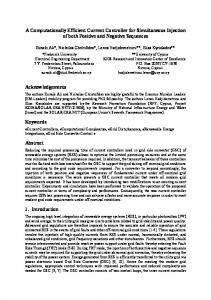
three-dimensional representation of this friction coe�cient function is shown in Fig. 5. The resultant function is a truncated prism. The inner member hose elements are subjected to an applied force F (from surrounding elements) and frich tion. The latter is transmitted between the hose and the two adjoining surfaces: the device and the core bulkheads. The acceleration of a hose element is given by F �F +F � f (dx /dt�dx /dt) h 12 23 12 2 1 � f (dx /dt�dx /dt )�k (x �x ) d2x 2= 23 2 3 2 2 20 m dt2 2 (1) The hose elements are connected laterally to adjoining hose elements. The corresponding acceleration of the inner core (connected directly to the bulkheads) is given by F �F � f (dx /dt �dx /dt)�k (x �x ) d2x 3= c 23 23 3 2 3 3 03 m dt2 3 (2) The friction laws F and F are typically of the form 13 12 shown in Fig. 3. The displacement and velocity of the hose element and inner core are obtained by successive integration of the acceleration equations. The ‘sticking’ action is implemented by means of an arti�cial increase in viscous friction coe�cient if the applied force is less than stiction (F ) in the low relative s velocity region. Two tolerances are de�ned and the coe�cient increases linearly from its nominal level ( f ) n to a very large (arti�cial ) maximum level ( f ). The corm responding relative velocity tolerance levels are v and n v . The following equation de�nes the linear increase in m the coe�cient. For negative velocity in the region of the origin, the relationship is f�f f �f n= m n (3 ) v�v v �v n m n A corresponding symmetrical relationship is used for positive velocity in the region of the origin. The transition points between velocity tolerances are governed by the discontinuity code described previously. The sign of
Fig. 5
Viscous friction as a function of relative velocity and net applied force
the sliding friction changes in a continuous linear fashion as the velocity changes sign. This is also under the control of the discontinuity code.
3
MODEL SIMULATION RESULTS
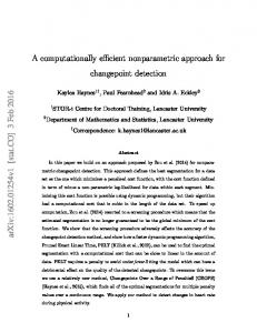
The model results presented were obtained using the AMESimTM [2] software package. In order to check the array model against experiment, a simple experimental test was necessary. The frictional characteristics were examined by testing with observed data for an array being pulled around a single bend. Constant inboard and outboard tensions were used for a �xed array speed of 0.3 m/s and this condition was replicated in the simulation. This is the simplest open-loop test conceivable without the complexity of a guidance route and control system. Two di�erent friction coe�cients are assessed for the array hose to device surface: a low value of 0.35 and a high value of 0.6. The relative velocities of the hose and bulkhead are monitored during the course of the simulation. Figure 6a shows that for the low coe�cient of friction, the hose moves in unison with the bulkheads and core. Figure 6b shows that for a high friction coe�cient of 0.6, a signi�cant de-registration occurs due to a di�erence in the hose and core velocities. This is induced by the higher frictional force between the surfaces and indicates a likely rucking condition. Experiment observations con�rm the simulation predictions, validating the model. Practical tests show that for a low friction coe�cient value of 0.35, the array passes over a bend without signi�cant de-registration of the bulkheads to hose whereas for a higher friction coe�cient of 0.6, large de-registration and hence rucking of the array is observed. From a computational viewpoint, the simulations run quickly, producing credible results throughout. The model was used for a full guidance system with a realistic electrohydraulic control system and simulations of all conceivable friction levels were performed without computational di�culties. Dynamic guidance route torsional e�ects, using the same generic friction model, were also simulated in a robust and rapid manner. As a �nal test of the robustness of the friction modelling technique, a co-simulation was performed with AMESimTM simulating the array and hydraulics with MATLABÒ SimulinkTM simulating the control electronics. This again performed in a rapid and robust manner. All the simulation results con�rmed expected behaviour but are not presented in this paper in order to maintain brevity. This shows that, for practical purposes, the model of sliding friction performs as required. The simulation times are signi�cantly faster than those obtained using alternative models for friction. The numerical integration routine is also a signi�cant factor in speed and robustness of simulation. The di�erential equation
Proc. Instn Mech. Engrs Vol. 217 Part I: J. Systems and Control Engineering Downloaded from pii.sagepub.com by guest on September 7, 2012
I04802 © IMechE 2003
A COMPUTATIONALLY EFFICIENT TECHNIQUE FOR MODELLING SLIDING FRICTION
Fig. 6
Hose and bulkhead core (a) in unison for friction coe�cient of 0.35 and (b) de-registered for friction coe�cient of 0.6
solver used is an extremely e�cient variable-order implicit technique [2 ], designed to handle discontinuities in sti� or non-sti� systems. The friction model described in this paper was compared with the widely used technique due to Stribeck [4]. A number of simulation runs were performed in order to compare the methods. The I04802 © IMechE 2003
145
simulation run times were typically 60 per cent of those for identical simulations using the Stribeck model. When using alternative friction models and integration routines that did not employ robust stick/slip coding logic, the simulation times were either orders of magnitude longer or simply did not complete.
Proc. Instn7,Mech. Downloaded from pii.sagepub.com by guest on September 2012
Engrs Vol. 217 Part I: J. Systems and Control Engineering
146
4
S P TOMLINSON, R W COOKE AND D C COSSERAT
CONCLUSIONS
A physically realistic computer modelling technique for the simulation of velocity-dependent sliding friction has been presented which is computationally e�cient. It overcomes the problems normally associated with models of this phenomenon, such as simulations stopping prematurely or giving unreliable results. The modelling technique described has three principal advantageous features: 1. It is general and allows any sensible friction–velocity relationship to be incorporated, either based on a deterministic equation or on an empirical relationship where friction levels are known at speci�ed velocities. 2. The transition from positive to negative relative surface velocity is continuous. This is achieved by arti�cially increasing the viscous friction coe�cient to ensure that ‘sticking’ of surfaces occurs when the applied force is below the limiting stiction level. This feature ensures that multiple simultaneous use of the technique, necessary for a wide range of practical systems, does not lead to computational problems such as simulation failure or excessive run times. 3. The model causality is such that friction is a function of the relative velocity between adjoining surfaces. The latter is readily obtained by numerical integration of acceleration terms determined from force equations. This enables the simulation of non-monotonic friction–relative velocity relationships to be implemented. The technique has been tested thoroughly and shown to be robust and execute quickly compared with other methods.
REFERENCES 1 Tomlinson, S. P., Baker, J. S., Rottier, P. J. and Swift, S. J. Development of a submarine fully reelable towed array outboard handling system (TAOS ) generic model. In Proceedings of IMDEX ASIA 99, International Maritime Defence Exhibition and Conference, Singapore, 4–7 May 1999. 2 Tomlinson, S. P. Use of AMESim to investigate feasibility of all-electric drives for reelable array handling systems. In NATO Modelling and Simulation Conference incorporating 3rd International Synthetic Environment Symposium, The Royal Military College of Science, Shrivenham, 24–26 October 2000.
3 Tomlinson, S. P., Baker, J. S. and Cowling, D. Simulation, control: submarine towed array handling systems. Generic assessment of fully reelable submarine towed-array handling systems; model and experiment-based. Sea Technol., July 2000, 10–16 (Compass Publishing, Arlington). 4 Armstrong-Helouvry, B. Control of machines with friction. In Friction as a Function of Velocity, 1991, Ch. 6, pp. 63–93 ( Kluwer, Dordrecht). 5 Tomlinson, S. P. The hydraulic automatic simulation package. PhD thesis, University of Bath, 1987, pp. 22–106. 6 Haessig, D. A. and Friedland, B. On the modelling and simulation of friction. J. Dynamic Systems, Measmt and Control, September 1991, 113, 354–362. 7 Tomlinson, S. P. and Bozin, A. Use of the MATLAB nonlinear identi�cation toll NLID to optimise parameter estimation in a dynamic response of two-stage relief valve model. In 3rd MATHMOD Conference, Vienna, Austria, February 2000. 8 Briscoe, B. J., Winkler, A. and Adam, M. J. A statistical analysis of the frictional forces generated between mono�laments during intermittent sliding. J. Phys. D: Appl. Phys., 1985, 18, 2143–2167. 9 Dickens, K., Sullivan, J. L. and Lancaster, J. K. Speed e�ects on the dry and lubricated wear of polymers. Wear, 1986, 112, 273–289. 10 Ettles, C. M. and Hardie, C. E. The friction of some polymers and elastomers at high values of pressure× velocity. J. Tribology, October 1988, 110, 678–683. 11 Sudarsan, U. and Kishor E�ect of load changes on dynamic coe�cient of friction of crystalline and amorphous materials. J. Mater. Sci., 1986, Letters 5, 198–200. 12 Bartenev, G. M., Lavrent’ev, V. V. and Voevodskii, V. S. Friction properties of highly elastic materials at high contact pressures. Lenin Moscow State Pedagogical Institute, Laboratory for Problems of Polymer Physics UDC 678.4.01:539.62, 1971, pp. 115–120. 13 Hoppe, B. Calculation of deformation component of friction force in sliding contact of viscoelastic and rigid bodies. Treni I Iznos, 1987, 8(3), 403–406 ( UDC 531.43/46:678.72). 14 Tanaka, K. Kinetic friction and dynamic elastic contact behaviour of polymers. Wear, 1984, 100, 243–262. 15 Lancaster, J. K. Friction and wear. In Polymer Science, 1972, Ch. 14, pp. 960–989 (North-Holland Publishing). 16 Richards, C. W., Tilley, D. G., Tomlinson, S. P. and Burrows, C. R. Type-insensitive codes for the simulation of �uid power systems. In Proceedings of ASME WAM, Dallas, Texas, 1990, paper 90-WA/FPST-6, pp. 1–6. 17 Richards, C. W., Tilley, D. G., Tomlinson, S. P. and Burrows, C. R. Bathfp—a second generation package for �uid power systems. In Proceedings of BHRA 9th International Symposium on Fluid Power, 9th International Fluid Power Symposium, Cambridge, April 1990, pp. 315–322.
Proc. Instn Mech. Engrs Vol. 217 Part I: J. Systems and Control Engineering Downloaded from pii.sagepub.com by guest on September 7, 2012
I04802 © IMechE 2003