1 < d i s t a n c e>500 ” A v en id a B r a s i l D i g i t a l ” 00 : 2 6 : 5 a : a 6 : 1 3 : 6 7 < l a t i t u d e>−22.8649888333 −43.2149178333 e s s i d 00 : 2 6 : 5 a : a 6 : 1 3 : 7 0 < l a t i t u d e>−22.8638633333 −43.2189613333
(2)
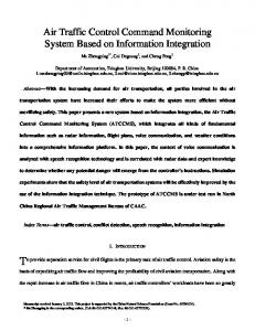
where vi is the OBU mean speed and HMRS (t − 1) is the previous harmonic mean value on the road segment. To identify in which road segment the OBU is, or define the vehicle direction, we use the last and the present RSUs. This verification is done using a local XML file, in the format of Listing 1. It is possible to check in the list the extension of the road segment and that the road segment is composed of two RSUs (lines 4, 8, and 16). The local file also stores information about each RSU, in this example: the ESSID (lines 7 and 15), MAC addresses, and geographic coordinates (lines 10, 11, 18, and 19). We consider that the client application knows the road where the vehicle is traveling. This is a input value of the client application. Figure 3 shows the steps of the communication between OBU and RSU as a diagram. DHCP operations fall into four
Fig. 3: DTraMS diagram. The maximum TTL value depends on the road characteristics, such as the number of lanes, length, and speed limit. On the one hand, a maximum TTL too small may not allow the update of the road conditions in distant road segments. The slower the road speed limit, the worse is this effect because
Algorithm 1 Algorithm executed by an OBU.
Algorithm 2 Algorithm executed by an RSU.
Input: RSSI, ESSID, and BSSID of the RSU. Output: The instant when the OBU crosses the RSU.
Input: The instant when the OBU has crossed the RSU. Output: Harmonic mean of road segments.
1: numRS = ((numRSU − 1) ∗ numD ); 2: actualP ower ← 0; 3: maxP ower ← 0; 4: while true do 5: Search for known ESSID; //monitor mode 6: if ESSID is known then 7: actualAP ← MACAP ; 8: Store actualP ower in a ordered vector; 9: Try to associate; 10: if It is associated then 11: Receive SCT from the RSU; 12: numLine ← 1; 13: while numLine < numRS do 14: if T T LrecentLine < T T LreceivedLine then x x 15: T T LrecentLine ← T T LreceivedLine ; x x 16: ConditionrecentLine ← ConditionreceivedLine ; x x 17: end if 18: numLine ← numLine + 1; 19: end while 20: while Associated do 21: if |maxP ower| > |receivedP ower| then 22: |maxP ower| ← |receivedP ower| 23: Store actualP ower in an ordered vector; 24: else 25: if |receivedP ower| − |maxP ower| >= 10 then 26: Store the instant of OBU passed by RSU; ext(RSy ) 27: v(Vx , RSy ) ← tx (RSUy )−tx (RSU ; y−1 ) 28: Update local SCT; 29: Send the SCT updated to associated RSU; 30: Disconnect; 31: previousAP ← recentAP ; 32: recentAP ← {}; 33: end if 34: Store recentP ower in vector; 35: end if 36: end while 37: else 38: Try to associate with the RSU; 39: end if 40: else 41: Search by known ESSID on received beacon frames; 42: end if 43: end while
1: numR S = ((numRSU − 1) ∗ numD ); 2: while true do 3: Receive association request; 4: Send the current local SCT plus the network settings; 5: Wait for an updated SCT; 6: Receive the updated SCT; 7: numLine ← 1; 8: while numLine < numRS do //Compare received SCT with local SCT; 9: if T T LRecentLine = 0 then x 10: T T LRecentLine ← T T LReceivedLine ; x x 11: ConditionRecentLine ← ConditionReceivedLine ; x x 12: else 13: if T T LRecentLine < T T LReceivedLine then x x 2 14: HMRS (t) = 1 ; 1 +
vehicles take longer to reach distant road segments. On the other hand, an overestimated maximum TTL can result in outdated information, especially desceibing farther segments. To compute the TTL value, we use the following equation:
T T L > p(i) ×
n X
tRSi ,
vi
HMRS (t−1)
15: T T LRecentLine ← T T LReceivedLine ; x x 16: ConditionRecentLine ← HMRS (t); x 17: end if 18: end if 19: numLine ← numLine + 1; 20: end while 21: end while
III.
F IELD E XPERIMENTS
AND
A NALYSIS
In the experiments, we use a real scenario set up in the campus of the Federal University of Rio de Janeiro, Brazil. The RSUs are installed inside hermetic boxes and powersupplied by 12 V batteries and a 5 V voltage regulator, as shown in Figures 4 and 5. The client application runs on a Sony Vaio laptop with a processor Intel I5-3210m, 6 GB of RAM, 640 GB of hard disk, and an IEEE 802.11 network interface. For comparison purposes, we use a GPS model u-Blox 5, which gives the OBU position four times per second. The client application was implemented using Python. In our experiments, we use two RSUs and one OBU. Figures 4 and 5 present the road segments. We had other vehicles travelling at the same time in different lanes. The OBU measures the association time (starting when OBU receives the first beacon from the RSU), the time required for IP configuration, the time to execute the exchange of tables, and the moment of disconnection. It is worh mentioning that our experimentation scenario was prone to intereferences from other wireless networks. We have detected 11 IEEE 802.11 b/g networks in channel 9 or 11. We use the channel 11 in the OBU.
(3)
i=1
where i is the current road segment, p(i) is the probability of traffic jam occurrence in that road segment, n is the number of road segments, and tRSi is the mean time to pass by the current road segment. The probability of traffic jam occurrence (p(i)) is a input value, based, i.e., on historical data.
Fig. 4: Road segment 1 of the scenario - UFRJ.
be to make the first access point as the sole responsible for distributing IP addresses. In the second option, the initial step would only happen when the vehicle enters the road.
Fig. 5: Road segment 2 of the scenario - UFRJ.
Figure 6 shows an experiment where the OBU crosses an RSU. The figure depicts the time intervals corresponding to each stage of the DTraMS algorithm. The moment when each stage finishes is represented. The mean speed of the vehicle is about 40km/h. The entire process takes about 17 seconds (from 15:05 to 15:22). The OBU always disconnects after passing by an RSU, when the RSSI value is 10 dBm lower than the maximum RSSI measured.
−90
RSSI
−80 −70
Another option is to consider IEEE 802.11 p [19], the 802.11 variant which is part of the WAVE (Wireless Access in Vehicular Environment) protocol suite. In the IEEE 802.11p standard, a station in “WAVE mode” can transmit and receive data frames without establishing a BSS (Basic Service Set). Consequently, OBUs do not need to wait for the association and authentication procedures before exchanging data. Stations with IEEE 802.11 p use the wildcard BSSID in the frames header. Using 802.11 p, the association time would be reduced. In the WAVE protocol family, the WAVE Short Message Protocol (WSMP) is an alternative to TCP/UDP and IPv6. WSMP allows applications to have direct control over physical layer characteristics, such as channel and transmission power used to send messages. The sending application also provides the MAC address of the target device, although there is the possibility of using the broadcast address. Even if IEEE 802.11p is specific for vehicular networks, we have used IEEE 802.11 b/g for two main reasons. First one is the possibility of evaluating the proposal in real scenarios since only a few 802.11p wireless cards are curently comercially available. The second reason is because IEEE 802.11b/g/n, besides its much larger availability, is present on a much larger variety of equipment, including smartphones, tablets, and laptops, and there is currently no reason for those type of devices to be equipped with the 802.11 p variant.
−60
−40 −30
15:05
15:10
15:15
15:20
15:25
15:30
15:35
Time MM:SS Beacons Find Association Receiving the table
Table received Disconnecting Waiting
Fig. 6: Steps of the DTraMS: Beacons, RSSI behavior of the received beacon from RSU; Find, instant when the OBU detects a known ESSID; Association, end of association process; Receiving the table and Table received, interval between request of the SCT and response; Desconnecting, instant when OBU disconnect to RSU; and Waiting, waiting to next RSU.
Time (seconds)
−50
30 25 20 15 10 5 0 1
2
3
4
5
6
7
8
Rounds Association IP Process
SCT Others
Fig. 7: Histogram - 8 rounds. Figure 7 presents the DTraMS behaviour in 8 rounds. Each round represents the moment when the vehicle reaches the end of a road segment. The time interval between the moment that the OBU detects a known ESSID and when it associates to the RSU varies from 6 to 11 seconds. It took 3 to 9 seconds to receive the network settings from the RSU plus the time needed to receive and send the SCT. The mean time to receive the SCT is 2 seconds. Experiments using fixed IP address in the OBU have reduced the time needed to finish the network configuration from 3-9 seconds to less than 1 second. The association and the reception of network settings are the steps that take longer. In this case, we can think of at least two options to reduce the time needed for the algorithm execution when using IEEE 802.11 b/g. The first is the the utilization of a predefined IP address in OBUs. The second option would
To analyze the accuracy of DTraMS, we compare the OBU and RSU positions in the moment when the received signal power is higher. The results show that with a received signal power as low as −60 dBm we have a discrepancy of less than 3 meters. Previous experiments present similar results even in scenarios with high number of vehicles and 802.11 networks [11]. According to Boukerche et al. [20], the error of location systems varies between 10 and 30m. Therefore, our result can be considered satisfactory since errors are minimized by predictable movements of client nodes. Figure 8 presents the traffic condition inferred on each road segment by both DTraMS and GPS. To generate a single condition using the GPS, we have calculated the harmonic
mean of all values obtained in the road segment. By default in the standard, used GPS define the OBU location every 0.25 seconds. For comparison purposes, we have varied this interval, via client application. The obtained results are very close, showing that the efficiency of DTraMS is quite similar to the best case, even using IEEE 80211 b/g. 45 40
Speed (km/h)
35 30 25 20 15 10 5 0
1
2
3
4
5
6
7
8
9
10
Rounds DTraMS GPS 4Hz
GPS 1Hz GPS 0.2Hz
GPS 1/60Hz
Fig. 8: Comparison between DTraMS and GPS results.
IV.
C ONCLUSIONS
This paper has presented DTraMS, a collaborative system for distributed monitoring of traffic using vehicular networks. In DTraMS, road-side units (RSUs) do not necessarily need to be connected to a control central, since vehicles fulfill the role of communication links, allowing each RSU to have information about traffic conditions on the road. Thus, DTraMS is well suited for highways without cellular coverage or energy infrastructure. Experiments were carried out in a real scenario with very similar results to those obtained by a high-precision GPS. DTraMS is accurate in detecting both the position of the vehicle, with discrepancy of less than 3 meters, and on estimating the road condition, focus of this paper. As future work we aim at simulating the DTraMS in larger scenarios using NS-3 [21], aiming at analyzing the amount of traffic generated by the system, its scalability with respect to the number of cars, as well as the minimum number of cars needed for the system to provide the traffic conditions. ACKNOWLEDGMENTS This work was partially funded by CAPES, COFECUB, FAPERJ, CNPq, and FINEP/FUNTTEL. R EFERENCES [1]
[2]
[3]
Directorate-General fo Energy and Transport, “European energy and transport. trends to 2030,” European Commision, Tech. Rep., 2004. [Online]. Available: http://ec.europa.eu/dgs/energy/transport/ figures/trends/2030/ Y. Gongjun, S. Olariu, and D. Popescu, “Notice: An architecture for the notification of traffic incidents,” Intelligent Transportation Systems Magazine, IEEE, vol. 4, no. 4, pp. 6–16, 2012. J. Hubaux, S. Capkun, and J. Luo, “The security and privacy of smart vehicles,” Security Privacy, IEEE, vol. 2, no. 3, pp. 49–55, May-June.
[4] M. Raya, P. Papadimitratos, and J.-P. Hubaux, “Securing vehicular communications,” Wireless Communications, IEEE, vol. 13, no. 5, pp. 8–15, Oct. 2006. [5] S. Y. Cheung, S. Coleri, B. Dundar, S. Ganesh, C.-W. Tan, and P. Varaiya, “Traffic Measurement and Vehicle Classification with a Single Magnetic Sensor,” 2004, Institute of Transportation Studies, Research Reports, Working Papers, Proceedings. [Online]. Available: http://EconPapers.repec.org/RePEc:cdl:itsrrp:qt2gv111tv [6] K. Kwong, R. Kavaler, R. Rajagopal, and P. Varaiya, “Arterial travel time estimation based on vehicle re-identification using wireless magnetic sensors,” Transportation Research Part C: Emerging Technologies, vol. 17, no. 6, pp. 586 – 606, 2009. [7] Q.-J. Kong, Q. Zhao, C. Wei, and Y. Liu, “Efficient traffic state estimation for large-scale urban road networks,” Intelligent Transportation Systems, IEEE Transactions on, vol. 14, no. 1, pp. 398–407, 2013. [8] P. Mohan, V. N. Padmanabhan, and R. Ramjee, “Nericell: rich monitoring of road and traffic conditions using mobile smartphones,” in Proceedings of the 6th ACM conference on Embedded network sensor systems, ser. SenSys ’08. New York, NY, USA: ACM, 2008, pp. 323– 336. [9] Google, “Google Maps,” 2011, accessed in August 2013. [Online]. Available: Availableinhttp://maps.google.com/support [10] D. Valerio, A. D’Alconzo, F. Ricciato, and W. Wiedermann, “Exploiting Cellular Networks for Road Traffic Estimation: A Survey and a Research Roadmap,” in Vehicular Technology Conference, 2009. VTC Spring 2009. IEEE 69th, April 2009, pp. 1 –5. [11] J. G. Ribeiro J´unior, M. E. M. Campista, and L. H. M. K. Costa, “Opportunistic System for Collaborative Traffic Monitoring Using Existing IEEE 802.11 Networks,” in Intelligent Vehicular Networking: V2V/V2I Communications and Applications - IEEE International Conference on Communications - ICC, Ottawa, Canada, Jun. 2012, pp. 7294 –7298. [12] J. A. Sanguesa, M. Fogue, P. Garrido, F. J. Martinez, J.-C. Cano, C. T. Calafate, and P. Manzoni, “An infrastructureless approach to estimate vehicular density in urban environments,” Sensors, vol. 13, no. 2, pp. 2399–2418, 2013. [13] A. Thiagarajan, L. Ravindranath, K. LaCurts, S. Madden, H. Balakrishnan, S. Toledo, and J. Eriksson, “VTrack: Accurate, Energy-aware Road Traffic Delay Estimation Using Mobile Phones,” in Proceedings of the 7th ACM Conference on Embedded Networked Sensor Systems, ser. SenSys’09. New York, NY, USA: ACM, 2009, pp. 85–98. [14] A. Carroll and G. Heiser, “An Analysis of Power Consumption in a Smartphone,” in Proceedings of the 2010 USENIX conference on USENIX annual technical conference, ser. USENIXATC’10. Berkeley, CA, USA: USENIX Association, 2010, pp. 21–21. [15] A. Balasubramanian, R. Mahajan, and A. Venkataramani, “Augmenting Mobile 3G using WiFi,” in Proceedings of the 8th international conference on Mobile systems, applications, and services, ser. MobiSys ’10. New York, NY, USA: ACM, 2010, pp. 209–222. [16] “IEEE Standard for Information Technology- Telecommunications and Information Exchange Between Systems-Local and Metropolitan Area Networks-Specific Requirements- Part 11: Wireless LAN Medium Access Control (MAC) and Physical Layer (PHY) Specifications,” ANSI/IEEE Std 802.11, 1999, pp. i –513, 2003. [17] IETF RFC 2131, “Dynamic Host Configuration Protocol,” Mar. 1997. [18] J. G. Ribeiro J´unior, L. H. M. K. Costa, M. E. M. Campista, I. M. Moraes, R. S. Alves, R. S. Couto, F. O. B. Silva, L. G. Valverde, M. L. D. Lanza, B. C. V. Camilo, and M. D. Amorim, “GT-ReBUS: Network Access on Bus of Universities,” Available in http://www.gta.ufrj.br/gt-rebus, Tech. Rep., 2011, acessed in August 2013. [19] Y. Du, L. Zhang, Y. Feng, Z. Ren, and Z. Wang, “Performance analysis and enhancement of ieee 802.11p/1609 protocol family in vehicular environments,” in Intelligent Transportation Systems (ITSC), 2010 13th International IEEE Conference on, 2010, pp. 1085–1090. [20] A. Boukerche, H. A. B. F. Oliveira, E. F. Nakamura, and A. A. F. Loureiro, “Vehicular ad hoc Networks: A New Challenge for Localization-Based Systems,” Comput. Commun., vol. 31, pp. 2838– 2849, July 2008. [21] NS-3 Consortium, “Network simulator - v3,” 2008, acessed in July 2013. [Online]. Available: http://www.nsnam.org/