Selection of appropriate technologies is dependent on a number of factors, including ... priate remediation technologies at hydrocarbon-contaminated sites in a ...
Journal of Soil Contamination, 2(2): (1993)
A Decision Framework for Selecting Remediation Technologies at Hydrocarbon-Contaminated Sites Neil M. Ram, David H. Bass, Robert Falotico, and Maureen Leahy Groundwater Technology, Inc., 3 Edgewater Drive, Norwood, MA 02062 ABSTRACT: A variety of remediation technologies are available to address hydrocarbon contamination, including free product recovery, soil venting, air sparging, groundwater recovery and treatment, and in situ bioremediation. These technologies address hydrocarbon contamination distributed between free, adsorbed, and dissolved phases in both the vadose and saturated zones. Selection of appropriate technologies is dependent on a number of factors, including contaminants, site-specific characteristics, clean-up goals, technology feasibility, cost, and regulatory and time requirements. This article describes a decision framework for selecting appropriate remediation technologies at hydrocarbon-contaminated sites in a structured and tiered manner. Decision modules include (1) site characterization and product recovery; (2) vadosezone treatment: soil venting, bioremediation, and excavation; (3) saturated zone treatment: sparging, bioremediation, groundwater recovery, and excavation; and (4) groundwater treatment: carbon, air stripping, advanced oxidation, and bioreactors. Selection criteria for treatment technologies that address vadose- and saturated-zone soils, as well as recovered groundwater, are described. The decision framework provides a systematic process to formulate solutions to complex problems and documents the rationale for selecting remediation systems designed to achieve closure at hydrocarbon-contaminated sites. KEY WORDS: hydrocarbon contamination, decision framework, remediation technologies, remediation selection, technology screening.
I. INTRODUCTION AND OBJECTIVES There are many applicable technologies for treating sites contaminated with petroleum hydrocarbon. The effectiveness of these technologies, however, is dependent on contaminant and site characteristics, regulatory requirements, and cost limitations. To design, construct, and operate the most cost-effective and applicable remediation technologies to achieve site closure, it is necessary to screen out inappropriate or costly remediation systems and to retain those systems that are best suited to site and contaminant characteristics. Unfortunately, remediation
Copyright© 1996, CRC Press, Inc. — Files may be downloaded for personal use only. Reproduction of this material without the consent of the publisher is prohibited.
1
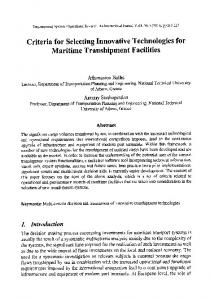
technologies are often selected because they are familiar and not because they are the most applicable or cost-effective for a given site. Figure 1 summarizes the applicable technologies for the remediation of soil and groundwater contaminated with petroleum hydrocarbon and presents a generalized hierarchy for selecting multiple technologies. These technologies may be subdivided into 1. Liquid-phase hydrocarbon (LPH) removal technologies 2. Vadose zone treatment technologies 3. Saturated zone treatment technologies 4. Treatment technologies for recovered groundwater 5. Off-gas treatment technologies Selection of technologies within these categories is based on (1) technology applicability; (2) regulatory acceptance; (3) cost; and (4) treatment time. Technology applicability is dependent on the effectiveness of a technology for treating specific contaminants for existing site conditions (i.e., soil type, aquifer characteristics, etc.). Different technologies have varying constraints, which are described in further detail in Section III. Technology applicability is also dependent on the availability of the technology, the implementability of the technology for the specific site conditions, and whether the technology is readily available (i.e., emerging, developing, or proven). Regulatory acceptance must also be considered based on the degree of difficulty that the user anticipates when obtaining a permit from local or state regulatory agencies to implement the technology. Treatment time and cost must also be considered so that technologies can be selected that achieve closure goals at minimum cost and time. Potential liabilities associated with site contamination and regulatory compliance may also impact the selection of remediation strategies. The purpose of a decision framework is to provide a consistent and technically sound approach for selecting appropriate remediation strategies for the clean up of contaminated sites. This approach is necessary to optimize technology selection based on closure requirements and other project goals and to document the technology selection process. The American Petroleum Institute (API) developed a “petroleum decision framework” to facilitate decision making for investigation and cleanup of petroleum release to soils and groundwater (API, 1990). Menu functions include initial response abatement, site assessment, and site remediation. The U.S. Department of Energy Pacific Northwest Laboratories (Kelly et al., 1992) has also developed a Remedial Action Assessment System (RAAS) that provides information about remedial action technologies. RAAS allows the user to assess remediation technologies through descriptive information and application data and provides technology applicability information and regulatory constraints. The RAAS system
Copyright© 1996, CRC Press, Inc. — Files may be downloaded for personal use only. Reproduction of this material without the consent of the publisher is prohibited.
2
Remediation strategies for petroleum-contaminated sites. FIGURE 1. Copyright© 1996, CRC Press, Inc. — Files may be downloaded for personal use only. Reproduction of this material without the consent of the publisher is prohibited.
3
runs on a Macintosh II and uses ORACLE database software. EPA’s Risk Reduction Engineering Laboratory (RREL) also has a treatability database that includes 33 treatment technologies, 13 aqueous matrices, and 5 solid matrices (Haztech News, May 1992). The database is accessible through the Alternative Treatment Technology Information Center (ATTIC), which is EPA’s database on hazardous waste-treatment technologies. EPA has also designed the Cost of Remediation Model (CORA) as an expert system for developing remediation cost information.
II. TECHNOLOGY DESCRIPTIONS To understand the decision framework for technology selection, it is important to understand the general principles of applicable technologies for the remediation of petroleum hydrocarbon-contaminated sites. Some information about technologies for treating petroleum-hydrocarbon contamination was compiled by Environmental Solutions, Inc. (March 1990) for the Western States Petroleum Institute (WSPI). The WSPI manual provides technology descriptions and an overview of the technology screening process. EPA has also compiled technology descriptions for processes that treat contaminated soils and sludges (USEPA, 1988). Emerging and developing technologies being investigated in EPA’s Superfund Innovative Treatment Evaluation Program (SITE) have also been described (USEPA, 1991).
A. Liquid-phase Hydrocarbon Removal Conventional LPH recovery is the recovery of LPH from the groundwater and it addresses the most concentrated phase of contamination and the source for vadoseand saturate-zone contamination. LPH recovery is often considered a short-term measure to prevent further impact to soil and groundwater and serves as a supplemental technology to other in situ remediation techniques. Generally speaking, as the viscosity of a given LPH increases and aquifer grain size/permeability decreases, residual saturation increases, resulting in less mobile LPH available for removal. It has also been shown that the position of the water table at the time of the loss as well as the thickness and areal extent of LNAPL accumulation have a direct impact on the amount of LPH removed. Low water-table conditions with minimal fluctuations offer the best conditions for product accumulation and removal on the groundwater surface. LPH recovery methods include: •
Total fluid extraction. This method involves direct removal of LPH and water as a combined waste stream. Once product and water are removed from the subsurface, an oil/water separator is used to remove the LPH from the water. Total fluid extraction is most applicable for small accumulations of LPH with low (T 25,000 gpd/ft) aquifer transmissivity to enable areal depression of the water table for product recovery.
•
Passive recovery. When a less active LPH recovery system is warranted, skimming bailers or a Filter Bucket® device may be deployed in wells or trenches to passively recover product. With these systems, LPH is gradually accumulated in the device for periodic removal manually. Passive recovery is most useful for small quantities of LPH in discrete, localized accumulations. The bailers and Filter Buckets® that can be used for this type of LPH recovery are the least expensive and easiest to deploy of all the LPH recovery systems.
Thermally assisted LPH removal involves injecting heat into the subsurface to decrease the viscosity of LPH. This decreases the residual saturation and thereby increases the amount of mobile LPH available for removal. Typically, heat is provided at locations throughout the LPH plume, and the flow of heat is controlled by a soil vapor extraction (SVE) system and/or by groundwater pumping. LPH recovery is otherwise performed in a manner similar to conventional LPH recovery. Heat may be supplied to the subsurface via hot air injection, steam injection, or radio frequency (RF) heating.
B. Vadose-Zone Treatment Technologies Soil vapor extraction removes volatile organic compounds (VOCs) such as benzene, toluene, ethylbenzene, and xylenes (BTEX) from unsaturated (vadose-zone) soils by inducing air flow through contaminated areas. SVE is typically performed by applying a vacuum to vertical vapor extraction wells screened through the level of soil contamination, using a vacuum blower. The resulting pressure gradient causes the soil gas to migrate through the soil pores toward the vapor extraction wells. VOCs are volatilized and transported out of the subsurface by the migrating soil gas. Johnson et al. (1990) summarized the general approach to the design, operation, and monitoring of in situ SVE systems. Additional information about
Copyright© 1996, CRC Press, Inc. — Files may be downloaded for personal use only. Reproduction of this material without the consent of the publisher is prohibited.
5
the use of SVE in remediation vadose-zone contamination has been described by Brown and Bass (1991). Thermally assisted SVE involves the injection of heat into the vadose zone to improve the performance of soil venting by increasing the vapor pressure of the contaminants to be removed. Typically, heat is provided at locations surrounding the vapor extraction wells, and the heat migrates inward along with the soil gas. Operation of the vent system is otherwise identical to conventional soil venting. Heat can be injected by one of three methods: •
Hot air injection. Air is heated and injected under pressure into the subsurface to increase the temperature. If catalytic or thermal oxidation of offgas is being used, most of the hot exhaust gas can be injected to heat the subsurface.
•
Steam injection. The heat content of steam is much greater than that of air at the same temperature because of the latent heat released when steam condenses. Steam injected into the subsurface will create some groundwater mounding as the steam condenses, so groundwater pumping ordinarily will be required.
•
RF heating. A radio frequency transmitting antenna is placed in a well and radio waves are directed into the zone of contamination. Although the price per BTU is higher than for steam or hot air injection (because it is generated electrically), the heat can be directed more evenly and more precisely. This is an emerging technology that has been used less frequently than hot air or steam injection.
Vented in situ percolation is a process in which chemicals that are present in the unsaturated zone can be treated by aerobic biodegradation. Naturally occurring bacteria are stimulated to degrade hydrocarbons by adding oxygen and inorganic nutrients. Oxygen is supplied to the vadose zone by applying a vacuum-inducing air flow through the soil. Inorganic nutrients in the form of ammonia and phosphate are then percolated through the soil to stimulate biodegradation. Volatile hydrocarbons are removed primarily by the physical action of venting, whereas adsorbed and heavier hydrocarbon components will be biodegraded. The extent of biodegradation can be estimated by monitoring the carbon dioxide in the vented gases. Inorganic nutrients are usually added periodically to the subsurface through the vent-system piping. Water (either treated recovered groundwater or fresh water) is regularly amended with nutrients and injected under supplied or gravity pressure to the vent system with the blower off. Alternatively, the nutrients can be infiltrated through horizontal slotted piping laid at intervals on the surface or in trenches just above the depth of contamination. Excavation and disposal or treatment of vadose-zone soils is generally the option of last resort. The in situ vadose-zone technologies previously described
Copyright© 1996, CRC Press, Inc. — Files may be downloaded for personal use only. Reproduction of this material without the consent of the publisher is prohibited.
6
offer the advantages of being relatively inexpensive, versatile, and may be able to achieve site closure within a desired time period. However, in situ technologies may require long-term monitoring to demonstrate effectiveness and are not implementable at certain sites. For example, very tight soils or soils containing nonvolatile and nonbiodegradable contaminants may not be amenable to the in situ technologies described previously. In such cases, soil excavation with disposal or on-site treatment may be the only alternative to remove sorbed-phase contamination from unsaturated soil. Although expensive, excavation does provide a permanent solution by rapidly removing the contaminant source. Once removed, contaminated soil can be transported to an off-site disposal facility or treated on site. Treatment technologies for excavated soil include (1) beneficial reuse (asphalt incorporation and construction reuse); (2) solidification/stabilization (chemical or biological stabilization processes); (3) chemical extraction (heap leaching and liquid/solid contactors); (4) volatilization (surface spreading, soil pile aeration, soil shredding); (5) chemical treatment (peroxide spraying); (6) bioremediation (biopiles, slurry reactors); and (7) low-temperature thermal treatment (low-temperature thermal stripping or soil roasting). High-temperature thermal treatment such as incineration, pyrolysis, and vitrification technologies are generally not considered for treating petroleum hydrocarbon-contaminated soil because of their high costs.
C. Saturated-Zone Treatment Technologies Air sparging involves forcing air under pressure into the contaminated saturated zone. Sparging creates air-filled porosity in the saturated zone that facilitates direct volatilization of contaminants from saturated soil and removes volatile organics from groundwater, acting in much the same way as an air stripper. Sparging also creates turbulence and improves mixing in the saturated zone, which increases the transfer of contaminants from saturated soils to groundwater. Sparging enhances natural biodegradation of some contaminants by maintaining high dissolved-oxygen levels. Sparging is generally implemented in conjunction with soil-vapor extraction so that the contaminated sparge air is collected to prevent potential migration to nearby basements or to prevent contaminating the vadose zone. Groundwater recovery and treatment may also be conducted to provide hydraulic control of the contaminant plume during sparging. The use of air sparging for treating volatile contaminants in the saturated zone has been discussed in further detail by Brown (1991). Steam sparging (sometimes called “steam injection”) involves the forced injection of pressurized air and steam into the saturated zone, generally at a point just below the vertical extent of contamination. All physical mechanisms for contamination removal are enhanced because increased temperature increases the vapor
Copyright© 1996, CRC Press, Inc. — Files may be downloaded for personal use only. Reproduction of this material without the consent of the publisher is prohibited.
7
pressure, Henry’s Law constant, and (usually) the solubility of the contaminants. However, bioremediation would usually be retarded by the high temperatures. Steam sparging should be considered whenever rapid remediation is mandatory or when the saturated zone is contaminated with nonbiodegradable or semivolatile compounds. Steam sparging should always be performed in conjunction with soilvapor extraction and groundwater pumping for recovery of sparged contaminants and to maintain hydraulic control of the contaminant plume. In situ bioremediation is a process in which petroleum products are degraded in situ by naturally occurring bacteria by the introduction of inorganic nutrients (nitrogen and phosphorus) and oxygen into the groundwater. The process treats both dissolved and adsorbed hydrocarbons. The process can be conducted with or without hydraulic control, depending on state requirements. As in bioremediation of the vadose zone, oxygen and nutrients are required to promote aerobic biodegradation. Air sparging may be used to introduce oxygen to the saturated zone and is subject to the same limitations and design requirements as described earlier. Hydrogen peroxide, which hydrolyzes to form dissolved oxygen in the groundwater, may also be used. However, the stability of peroxide in site soil and groundwater influences its effectiveness. If peroxide hydrolyzes too rapidly, oxygen will only be supplied to the groundwater for a short distance away from the injection point. A laboratory measurement of peroxide stability in site materials is therefore recommended to estimate effectiveness. Inorganic nutrients and peroxide are usually added to the subsurface through a groundwater reinjection system. Groundwater is recovered downgradient of the contaminated area, treated, amended with nutrients, and reinjected upgradient of the contaminant plume. If hydraulic control is required, only a portion of the recovered groundwater is reinjected. The nutrient-amended groundwater can be reinjected through vertical points (e.g., monitoring wells) or through horizontal slotted piping in trenching. The goal is to inject the nutrient-amended groundwater at or near the groundwater table. Nutrients will be retarded by soil adsorption if the solution is delivered in the vadose zone. Further information about the use of in situ bioremediation of petroleum-contaminated soil can be found in review articles by Hicks and Brown (1990), Arvin et al. (1988), and Litchfield and Clark (1973). Excavation and disposal or treatment of saturated-zone soil is again the option of last resort. Although in situ treatment of saturated-zone soil is generally the most cost-effective method for removing contamination from this matrix, site or contaminant characteristics or expedited remediation objectives may require that saturated-soil excavation be considered for sorbed-phase contamination in the saturated zone. In addition to the technologies described earlier for excavated soil, dewatering and treatment would be needed to meet regulatory-based discharge levels. Soil excavation and dewatering are often used in underground storage-tank removal operations where the excavation pit intersects the groundwater table.
Copyright© 1996, CRC Press, Inc. — Files may be downloaded for personal use only. Reproduction of this material without the consent of the publisher is prohibited.
8
D. Groundwater Recovery and Treatment Groundwater treatment consists of (1) groundwater withdrawal from the subsurface and (2) above-ground treatment of recovered groundwater. Additionally, groundwater containment technologies may be used to gain hydraulic control of contaminant plumes. Groundwater pumping is primarily used as a containment strategy. It has been shown to enhance remediation but is effective as a sole remediation technique for only very soluble contaminants such as MTBE. Groundwater pumping/containment technologies can be considered either active or passive. Active methods include direct containment and removal of contaminated groundwater using recovery wells, well points, or interceptor trenches/ barriers. Passive methods redirect the flow of groundwater or confine the affected groundwater to a specific area using slurry walls, sheet piles, and impermeable caps. The use of a given method depends on site hydrogeologic conditions and remediation goals. Active containment methods include: •
Recovery wells are used where the soil is fairly permeable, especially with depth as in clean sands or coarser granular soils, and where the saturated thickness is sufficient to submerge the well screen and pump as the water table is lowered under pumping conditions. Recovery wells with individual submersible pumps can be installed within or on the perimeter of the zone to be contained.
•
Well points are constructed of small well screens less than 4 in in diameter and less than 5 ft long. Individual well points are usually attached to a common header pipe and connected to a well-point pump. They are used in fairly cohesive and fine-grained soils and are very useful where the desired drawdown depth is only a short distance above an impermeable layer. Where there is adequate saturated thickness and a higher pumping rate, deeper recovery wells are better suited.
•
Interceptor trenches are constructed by excavating a continuous slot in the subsurface and backfilling the excavation with a permeable material to permit drainage. More sophisticated methods include the installation of a continuous, perforated drainage pipe in the bottom of the trench and/or vertical sumps where the collected water is pumped out for treatment/ disposal. Interceptor trenches need not fully penetrate the saturated zone of concern and they provide a continuous positive cutoff of groundwater where contaminant breakthrough is not likely to occur. The use of impermeable barriers/liners on the downgradient sides of trenches can also enhance recovery and containment of impacted groundwater. They are best suited for low-permeability soils with a shallow depth to groundwater to minimize
Copyright© 1996, CRC Press, Inc. — Files may be downloaded for personal use only. Reproduction of this material without the consent of the publisher is prohibited.
9
construction constraints and where treatment/disposal of excavated soils will not present regulatory problems. Passive containment methods include: •
Slurry walls, also known as grout curtains, are cutoff trenches that are backfilled with impermeable material such as bentonite. They can serve as an adequate cutoff to contaminant migration if (1) they are installed so that they can be tied into an impermeable base that is not too deep; (2) they do not develop cracks or gaps through which contaminant breakthrough will occur; and (3) if there is not too much pressure buildup on the upgradient side that would force the contaminants to skirt around the perimeter of the wall. They are best suited for relatively low-permeability conditions in shallow aquifers.
•
Sheet piles are commonly fashioned as steel plates driven into the subgrade below the water table and secured into an impermeable base at depth. For these devices to be feasible, the impermeable base must not be too deep. Also, because the sheet piles are placed in an overlapping manner adjacent to one another, there are gaps that can allow contaminants to migrate through. They are best suited to shallow water-table conditions with low-tomoderate permeability. The most appropriate application of sheet walls is developing flow barriers and containment cells for short-term dewatering projects.
•
Impermeable caps provide a means for cutoff or diversion of vertical recharge and therefore serve to reduce horizontal groundwater flow and contaminant transport. They can be very costly to construct and are only appropriate for large-scale applications.
Groundwater treatment technologies for recovered groundwater containing petroleum-hydrocarbon contamination generally consist of either separation technologies such as (1) liquid-phase carbon adsorption and (2) air stripping, or destructive technologies such as (3) advanced oxidation and (4) bioreactors. Separation technologies are generally the most cost-effective approach for treating recovered groundwater containing petroleum-hydrocarbon contamination, although off-gas treatment requirements for air strippers and carbon disposal costs may add significantly to total treatment costs. Advanced oxidation and bioreactors should be considered for treating recovered groundwater that is cocontaminated with organics that are not amenable to air stripping and carbon-adsorption treatment. Advanced oxidation is effective for treating aromatic compounds such as BTEX as well as water-soluble contaminants (such as phenols) that cannot be removed efficiently by air stripping or activated carbon. Bioreactors can also effectively treat BTEX and soluble compounds such as phenol, alcohols, and ketones.
Copyright© 1996, CRC Press, Inc. — Files may be downloaded for personal use only. Reproduction of this material without the consent of the publisher is prohibited.
10
Liquid phase adsorption is the accumulation of dissolved chemicals (adsorbate) from liquid phase onto a surface of a solid (adsorbent). The adsorptive properties of activated carbon are attributable mainly to its highly porous structure and resulting large surface area. Contaminated groundwater is generally treated by passing it sequentially through two vessels containing activated carbon until breakthrough is observed in the first carbon unit. Review articles on the use of activated carbon for the removal of aqueous-phase contaminants have been prepared by Speth (1990) and Clark and Adams (1991b). Air stripping is the process of removing volatile contaminants from a liquid stream by contacting the liquid with air. The air and liquid flows are generally countercurrent. The effectiveness of contaminant removal improves with increasing values of the Henry’s Law constant of the contaminant, the air-to-water ratio, the stripping factor (equal to Henry’s Law constant multiplied by the air-to-water ratio), and the size of the air stripper. A variety of proven air stripper designs are available: conventional packed tower, countercurrent aeration trays, venturi air injection systems, and sequential air diffuser chambers. Emerging air stripper designs include (1) heated air strippers that recycle waste heat from off-gas treatment units to enhance removal of less volatile compounds such as methyl tertiary butyl ether (MTBE) and (2) closed-loop stripping to prevent iron or calcium fouling of air-stripper packing. Additional information about the use of air stripping for the removal of aqueous volatile compounds can be found in Clark and Adams (1991a) and Cummins and Westrick (1990). Advanced oxidation processes destroy aqueous contaminants by reaction with free hydroxyl radicals. The hydroxyl radicals are typically produced using combinations of ultraviolet radiation, ozone, and/or hydrogen peroxide. Advanced oxidation can be used for treatment of water streams contaminated with aromatic compounds such as BTEX, double-bonded organic compounds such as trichloroethylene (TCE) and tetrachloroethylene (PCE), and other compounds, including sulfide, cyanide, chlorophenols, polychlorinated biphenyls (PCBs), polynuclear aromatic hydrocarbons (PAHs), and some pesticides. Advanced oxidation, however, is less cost-effective in treating saturated organic compounds such as trichloroethane (TCA), dichloroethane (DCA), MBTE, alcohols, ketones, and saturated petroleum hydrocarbons. Review articles on the use of advanced oxidation for treating aqueous organic contaminants have been prepared by Roy (1990) and Peyton (1990). Bioreactors are used to degrade many organic compounds found in groundwater using bacteria in a reactor. Recovered groundwater is amended with inorganic nutrients (nitrogen and phosphate) and fed into the reactor tank. Oxygen is supplied through air diffusers at the bottom of the bioreactor. Bioreactors can provide cost-effective treatment of BTEX when carbon loading is very high or when off-gas treatment is necessary. Removal rates can be
Copyright© 1996, CRC Press, Inc. — Files may be downloaded for personal use only. Reproduction of this material without the consent of the publisher is prohibited.
11
greater than 99% with proper design. A laboratory treatability test is recommended to properly size the reactor. Two types of bioreactors are •
Fixed film bioreactors. Hydrocarbon-degrading bacteria attach to a solid support media in the reactor and form a biofilm. This attachment allows the bacterial biomass to be retained in the reactor. The biofilm is stable to a wide range of fluctuating contaminant concentrations and mixtures encountered in groundwater treatment. The biofilm can withstand sudden high-shock loadings and remain stable in the presence of very low-contaminant concentrations.
•
Suspended growth reactors. Bacteria grow in suspension within the reactor and are washed out with the effluent. These reactors are often used for waste streams with high-carbon loading.
E. Offgas Treatment Technologies Offgas treatment may be required from air-stripping units or soil-vapor extraction systems to limit hydrocarbon discharge to the atmosphere. Requirements vary between states. Offgas treatment of hydrocarbon can be achieved using (1) vaporphase adsorption; (2) catalytic oxidation; or (3) thermal-oxidation treatment. The relative costs of these technologies for treating hydrocarbon vapors have been reviewed by Kroopnick (1991). Vapor phase adsorption is the accumulation of a particular chemical from an offgas stream onto the surface of a solid. Contaminated offgas is generally treated by passing it sequentially through two vessels containing activated carbon until breakthrough is observed in the first carbon unit. Because vapor-phase carbon typically adsorbs five to 20 times more of a given contaminant per pound than liquid-phase carbon, air stripping with carbon treatment of offgas is often more cost-effective than liquid-phase carbon treatment alone. Catalytic oxidation destroys organic contaminants in vapor streams by reacting with atmospheric oxygen on a hot catalytic surface to produce carbon dioxide and water. The catalyst is heated electrically in units with a treatment capacity of less than 500 scfm and with propane or methane in larger units. Thermal oxidation destroys organic contaminants in vapor streams by reacting with atmospheric oxygen to produce carbon dioxide and water. Combustion takes place in a furnace that is usually fueled with methane or propane. Thermal oxidation units have lower initial costs than catalytic oxidation units but are usually more expensive to operation because of higher fuel requirements.
Copyright© 1996, CRC Press, Inc. — Files may be downloaded for personal use only. Reproduction of this material without the consent of the publisher is prohibited.
12
III. THE REMEDIATION DECISION FRAMEWORK To select appropriate technologies the following information is needed: Applicability of technology to site contaminants: Contaminant properties can often provide a general indication about the applicability of treatment technologies to remove such contaminants from environmental media. For example, contaminants in the vadose zone that exhibit a vapor pressure greater than 1 mmHg are generally amenable to soil-vapor extraction. Sorbed-phase contaminants in the saturated zone can usually be sparged if they have a dimensionless Henry’s Law constant greater than 0.1 and a vapor pressure greater than 1 mmHg. Chemicals with a dimensionless Henry’s constant greater than 0.1 can routinely be removed from recovered groundwater by air stripping. Other contaminant properties such as solubility, absorbability, and biodegradability indicate applicable treatment technologies. Variations in technology design: Technologies can be designed and implemented in various configurations to optimize treatment effectiveness and project goals. Soil-vapor extraction, for example, can be enhanced by concurrent groundwater pumping to expose contaminants at the groundwater capillary fringe. Horizontal vapor-extraction wells may also be considered when the depth to groundwater is less than 5 ft to provide more effective airflow in the vadose zone. Surface sealing may also enhance soil-vapor extraction. Air sparging can be conducted with or without concurrent soil venting and/or groundwater pumping. There are also many different types of air stripper designs with and without offgas treatment. Selection of the best technology design variation is dependent on many factors including site characteristics, design flow, regulatory requirements, and treatment objectives. Site characteristics: The applicability of treatment technologies is highly dependent on site characteristics. Both soil venting and sparging technologies require fairly permeable formations to allow sufficient airflow through the subsurface. The radius-of-influence (ROI) for vent or sparge points must generally be greater than 10 ft to provide a cost-effective remediation system design. Selection of LPH and groundwater recovery systems is dependent on both the transmissivity of the aquifer and the depth to groundwater. Soil characteristics will also impact the ability to augment the growth of naturally occurring microorganisms through the addition of nutrients and oxygen. Regulatory acceptance of technology and required permits: Different state regulatory agencies have varying requirements for groundwater withdrawal, groundwater discharge, and air discharges. The need for offgas treatment from
Copyright© 1996, CRC Press, Inc. — Files may be downloaded for personal use only. Reproduction of this material without the consent of the publisher is prohibited.
13
an air-stripping unit, for example, may make that technology cost-prohibitive when compared with aqueous carbon adsorption. Injection of nutrients into groundwater to augment naturally occurring microorganisms may not be permitted by some state agencies because of the concern about nitrates in groundwater. Technology availability: Although some technologies such as air stripping, carbon adsorption, and soil venting are readily available and widely used, others are just beginning to be used for remediation of hydrocarbon-contaminated sites. Air sparging has gained much acceptance over the past few years and steam sparging is being increasingly considered for treatment of less volatile contaminants or where expedited treatment is desired. Emerging technologies such as closed-loop stripping may also be applicable where offgas treatment is required and chemical or biological fouling is a problem. The availability and proven effectiveness of such technologies should be considered during the technology selection process. Treatment time objectives: Property transfer deadlines sometimes require expedited remediation, usually at higher costs. Soil contamination in either the vadose or saturated zones can be expedited by hot air or steam injection that results in a more favorable Henry’s Law constant and subsequent volatilization and removal of contaminants from the subsurface. Steam stripping may also be used to enhance and expedite volatilization of contaminants from recovered groundwater. In extreme cases, soil excavation with subsequent above-ground treatment or disposal may be considered to remove sorbedphase contamination. Project life-cycle costs: Project life-cycle costs consist of all expenses that are incurred for site assessment and remediation over a project’s lifetime. These costs include site assessment and remediation, site engineering and design, capital costs, operation and maintenance requirements, monitoring, and project management. The remediation system having the lowest possible present value cost, which achieves project objectives in terms of both closure goals and treatment time, should be selected. Obviously, capital costs must be carefully weighed against the estimated treatment time required to achieve closure. Administrative and potential litigation costs should also be considered in selecting the remediation strategy. Decision analysis in remediation planning is discussed in further detail by Angell (1990). These considerations are interactive and complex. Therefore, a decision framework provides a methodology for reviewing the various contaminant, site, regulatory, cost, and time constraints that impact technology selection. Given the multitude of cost, time, contaminant, site, and technology con-
Copyright© 1996, CRC Press, Inc. — Files may be downloaded for personal use only. Reproduction of this material without the consent of the publisher is prohibited.
14
FIGURE 2. Decision framework for remediation technologies.
straints, a decision framework provides a structured progression of decision points consisting of technology or site applicability criteria. The outcome of these decision points directs the user to subsequent decision points and
Copyright© 1996, CRC Press, Inc. — Files may be downloaded for personal use only. Reproduction of this material without the consent of the publisher is prohibited.
15
ultimately aids in selecting applicable technologies for contaminated environmental media. Figure 2 summarizes the general decision-making process for selecting remediation technologies at sites contaminated with petroleum hydrocarbon. The hierarchy considers LPH-removal technologies first because they address the most concentrated source of contamination. In situ vadose- and saturated-zone technologies are then considered, followed by groundwater pump and treatment technologies, which do not generally address contaminant source removal directly and are therefore less desirable. Figure 2 also emphasizes the importance of site characterization and establishing closure goals so that technology applicability and remediation criteria can be adequately assessed. For each of the technology boxes shown in Figure 2, additional detailed decision points are needed to determine applicable technologies for LPH, vadose-zone, saturated-zone, groundwater pump and treatment, and offgas technologies. Decision-making criteria for several technologies are illustrated in Table 1. These criteria are then placed into a decision framework for selecting the most appropriate technologies based on site conditions, contaminant properties, and desired treatment time. A detailed decision framework for selecting groundwater withdrawal systems is shown in Figure 3. The decision points include: •
Does the aquifer exhibit low (T < 1000 gpd/ft), medium (1000 gpd/ft < T < 25,000 gpd/ft), or high (T > 25,000 gpd/ft) transmissivity?
•
Is the depth to water greater than or less than 10 ft?
•
Is the saturated-zone thickness greater than or less than 10 ft?
Based on these decision points, one of nine different groundwater recovery systems is selected as being the most applicable for the associated site conditions. Figure 4 provides another example of the decision framework for soil-vapor extraction. The decision points include: •
Is LPH < 6 in to 2 ft or is the vadose zone contaminated?
•
Is expedited remediation desired?
•
Is the depth to water greater than about 3 ft?
•
Do the contaminants exhibit a vapor pressure > 1 mmHg?
•
Does the formation exhibit a soil-vapor extraction ROI greater than about 10 ft?
•
Is offgas treatment required?
Copyright© 1996, CRC Press, Inc. — Files may be downloaded for personal use only. Reproduction of this material without the consent of the publisher is prohibited.
16
Copyright© 1996, CRC Press, Inc. — Files may be downloaded for personal use only. Reproduction of this material without the consent of the publisher is prohibited.
17
LPH less than about 0.5 ft, contaminants with Vp >1 mm Hg (BTEX, gasoline, MTBE, PCE, TCE, TCA, mineral spirits, MeOH, Acetone, MEK, etc.)
Vadose zone Soil vapor extraction
Excavation
In situ bioremediation
Saturated zone Sparging
Excavation
All soils and contaminants
Contaminants in saturated zone with KH >0.1 and Vp > 1 mmHg; Contaminants: BTEX, gasoline, PCE, TCE, TCA, mineral spirits Any biodegradable chemical in the saturated zone; inhibited by pH extremes, heavy metals, and toxic chemicals
All soils and contaminants
Any aerobically biodegradable chemical in the vadose zone
All lighter-than-water petrochemicals except for the most viscous fuel and lube oils
LPH recovery LPH withdrawal
In situ percolation (bioremediation)
Applicability
Technology
TABLE 1 Technology Applicability
All soil types
Hydraulic conductivity >10–5 cm/sec (silty sand or better); At least 5 ft of saturated thickness Nutrients are transported better in more permeable soil
All soil types
Works better in permeable soils; depth-to-water greater than 3 ft
Permeable soils, ROI >10 ft depth-to-water greater than 3 ft
Works better with more permeable soils
Soil type and saturated zone characteristics
Oxygen supplied by sparging or peroxide addition; nutrient addition with groundwater recovery and reinjection Dewatering needed, groundwater containment may be used (slurry walls, sheet piles)
Dewatering may be used to expose soils in capillary fringe Hot air, steam, and cyclic sparging; concurrent groundwater pumping
Total fluid extraction, passive bailers, dual pump recovery, recovery wells, thermally assisted LPH recovery, mop and disk skimmers Thermally assisted venting, horizontal venting, surface sealing, passive vent points, closed loop venting, concurrent groundwater pumping for VOCs in capillary fringe Oxygen and nutrients need to be supplied to the subsurface
Variations
Very high
Moderate to high
Low
High
Low to moderate
Low
Variable
Cost
Permits for dewatering operations
Water discharge for nutrient injection, air discharge if performed with sparging/ venting
Air discharge permit may be required when soil venting used to provide oxygen On-site treatment of excavated soil may require permitting Air discharge permit; water discharge if concurrent groundwater pumping
Air discharge permit may be required
Groundwater discharge, product storage, and possibly, groundwater withdrawal
Permits
Copyright© 1996, CRC Press, Inc. — Files may be downloaded for personal use only. Reproduction of this material without the consent of the publisher is prohibited.
18 Adsorptive capacity generally increases with increasing molecular weight Conventional units can treat all compounds containing carbon, hydrogen, and oxygen. Concentrations should not exceed about 20% of the LEL Compounds containing carbon, hydrogen, and oxygen; usually not amenable to halogen-containing compounds
Offgas Treatment Vapor-phase carbon Catalytic oxidation
Variations
NA
Exhaust gas scrubbing may be required
Some units can treat chlorinated compounds, exhaust gas scrubbing may be required
NA
NA
Fixed film and suspended growth reactors Pretreatment dehumidification; on-site regeneration
See groundwater recovery
Packed towers, low profile, heated and closed loop air stripping; offgas treatment may be required Hydroxy/radicals produced by combinations of UV, ozone, and peroxide
High pressure (75 to 150 psi) and low pressure (12 to 15 psi)
Recovery wells, well points, interceptor trenches
Abbreviations: NA, Not applicable; LEL, Lower explosion limit; ROI, Radius-of-influence; LHP, Liquid-phase hydrocarbon.
Thermal oxidation
Bioreactors
See groundwater recovery
See groundwater recovery
Compounds with KH >0.1; contaminants with KH between 0.01–0.1 may require an air:water ratio >100 Most effective on sulfide cyanide, double-bonded organics (PCE, TCE), BTEX, phenols chlorophenols, PCBs, PAHs, some pesticides Any biodegradable compound
Air stripping
Advanced oxidation
See groundwater recovery
Removal of compounds with low solubility/high adsorptivity
zone characteristics Transmissivity, depth-towater and saturated-zone thickness determine optimal strategy
Uses: (1) LPH recovery, (2) provides hydraulic control of contaminant plume, (3) pump and treatment technologies
Groundwater recovery and treatment Groundwater recovery Liquid-phase carbon
Soil type and saturated Applicability
Technology
TABLE 1 (continued) Technology Applicability Cost
Moderate to high
Moderate to high
Moderate to high Moderate
Low to high depending on contaminant loading Low, if no offgas treatment required Moderate to high
Variable
Permits
Air discharge permit
Air discharge permit
Air discharge permit
Water discharge permits
Water discharge permit
Air and water discharge permits
Water discharge
Well installation, groundwater withdrawal and groundwater discharge
Groundwater pumping and treatment: Groundwater recovery (H). FIGURE 3. Copyright© 1996, CRC Press, Inc. — Files may be downloaded for personal use only. Reproduction of this material without the consent of the publisher is prohibited.
19
Vadose-zone treatment: Soil-vapor extraction (A, B, D). FIGURE 4. Copyright© 1996, CRC Press, Inc. — Files may be downloaded for personal use only. Reproduction of this material without the consent of the publisher is prohibited.
20
These decision points guide the user to different technology options consisting of a variety of soil vapor extraction configurations. Alternatively, contamination or site properties may not be amenable to soil vapor extraction in which case, bioremediation or soil excavation may be considered. Additional decision frameworks for LPH recovery, in situ vadose-zone bioremediation, saturated-zone sparging, saturated-zone bioremediation, and treatment of recovered groundwater using either carbon, air stripping, or advanced oxidation, have also been developed. In addition to technology applicability, the selection of remediation technologies must also consider additional factors: cost, desired treatment time, technology availability, and regulatory acceptance. When all these criteria are placed into a decision framework, remediation technologies can be selected in a systematic and logical manner to achieve project goals. The decision framework also documents the technology selection process for potential future needs. The decision framework transforms a complex and multifaceted problem into a series of discrete and understandable decision points that can be used to select the most desirable remediation strategy to achieve site closure.
IV. TECHNOLOGY INTEGRATION Remediation technologies can work together to complement their effectiveness in degrading or removing site contamination. Figure 5 illustrates the interaction between a number of technologies that are typically used at petroleum hydrocarbon-contaminated sites. Although soil-vapor extraction is primarily directed at removing volatiles from the vadose zone, it also provides oxygen to enhance vadose-zone bioremediation, removes sparged air, and decreases adsorbed-phase contamination. Air sparging directly volatilizes sorbed-phase contamination in the saturated zone while additionally providing oxygen for saturated-zone bioremediation. Groundwater pump and treatment technology removes aqueous-phase contamination and provides hydraulic control during sparging. These interactions enhance the effectiveness of the individual technologies thereby providing more effective remediation. The decision framework presented herein is a valuable tool in selecting technologies for the remediation of sites contaminated with petroleum hydrocarbon by providing a systematic process to formulate defensible solutions to complex problems.
Copyright© 1996, CRC Press, Inc. — Files may be downloaded for personal use only. Reproduction of this material without the consent of the publisher is prohibited.
21
System integration. FIGURE 5. Copyright© 1996, CRC Press, Inc. — Files may be downloaded for personal use only. Reproduction of this material without the consent of the publisher is prohibited.
22
REFERENCES American Petroleum Institute. 1990. Petroleum Release Decision Framework. Angell, K. Selection Methodology for Environmental Remediation Planning. Presented at MidAtlantic Environmental Exposition, Baltimore, MD. (April 9–11, 1990). Arvin, E., Godsy, E. M., Grbic-Galic, D., and Jensen, B., Microbial Degradation of Oil and Creosote Related Aromatic Compounds under Aerobic and Anaerobic Conditions. International Conference on Physicochemical and Biological Detoxification of Hazardous Wastes, Atlantic City, NJ. (May 3–5, 1988). Brown, R. A. and Fraxedas, R., Air-Sparging — Extending Volatilization to Contaminated Aquifers. Presented at the Symposium on Soil Venting, Robert S. Kerr Environmental Research Laboratory, Houston, TX. (April 29–May 1, 1991). Brown, R. A. and Davis Bass: Use of Aeration in Environmental Clean-ups. Presented at the MidAtlantic Environmental Expo, Baltimore, MD. (April 9–11, 1991). Clark, R. M. and Adams, J. Q., 1991a. EPA’s Drinking Water and Groundwater Remediation Cost Evaluation: Air Stripping. Chelsea, MI, Lewis Publishers. Clark, M. and Adams, J. Q., 1991b. EPA’s Drinking Water and Groundwater Remediation Cost Evaluation: Granular Activated Carbon. Chelsea, MI, Lewis Publishers. Cummins, M. D. and Westrick, J. W., 1990. Treatment technologies and costs for removing volatile organic compounds from water: aeration. In: Significance and Treatment of Volatile Organic Compounds in Water Supplies. (N. M. Ram, R. F. Christman, and K. P. Cantor, Eds.) Chelsea, MI, Lewis Publishers. Environmental Solutions, Inc., Irvine, California, prepared for Western States Petroleum Association, March 1990. HazTech News, Vol. 7, No. 10, p. 78 (May 14, 1992). Hicks, R. J. and Brown, R. A., In-Situ Bioremediation of Petroleum Hydrocarbons. Presented at the Water Pollution Control Federation Annual Conference, Washington, DC (October 7–11, 1990). Johnson, P. C., Stanley, C. C., Kemblowski, M. W., Byers, D. L., and Colthart, J. D., 1990. A practical approach to the design, operation, and monitoring of in situ soil-venting systems. Groundwater Monitoring Review, Spring Issue. Kelly, A., Pennock, S. J., Bohn, and White, M. K., U.S. Department of Energy Pacific Northwest Laboratories, Expert Software that Matches Remediation Site and Strategy. Remediation, pp. 183–198, (Spring, 1992). Kroopnick, P. M., Life-cycle costs for the treatment of hydrocarbon vapor extracted during soil venting. In: Proceedings: Petroleum Hydrocarbons and Organic Chemicals in Groundwater, National Water Well Association, Houston, TX (November 1991). Litchfield, J. H. and Clark, L. C., Final report on bacterial activity in groundwater containing petroleum products. Project OS 21.1, Committee on Environmental Affairs, American Petroleum Institute (API Publication No. 4211, November 12, 1973). Peyton, G. R. 1990. Oxidative treatment methods for removal of organic compounds from drinking water supplies. In: Significance and Treatment of Volatile Organic Compounds in Water Supplies. (N. M. Ram, R. F. Christman, and K. P. Cantor, Eds.). Chelsea, MI, Lewis Publishers. Roy, K. A. 1990. UV-Oxidation Technology. Hazmat World pp. 35–50. Speth, T. F. 1990. Removal of volatile organic compounds from drinking water by adsorption. In: Significance and Treatment of Volatile Organic Compounds in Water Supplies. (N. M. Ram, R. F. Christman, and K. P. Cantor, Eds.) Chelsea, MI, Lewis Publishers. USEPA. Cost of Remedial Action (CORA) Model. Contact: 703–478–3566. USEPA: The Superfund Innovative Technology Evaluation Program (SITE). Technology Profiles, 4th ed. EPA/540/5–91/008 (November 1991).
Copyright© 1996, CRC Press, Inc. — Files may be downloaded for personal use only. Reproduction of this material without the consent of the publisher is prohibited.
23
USEPA: Technology Screening Guide for Treatment of CERCLA Soils and Sludges. EPA/540/2– 88/004 (September 1988). USEPA: Alternative treatment technology information center (ATTIC). Research and Development (RD-681). EPA/600/M-91/049 (November 1991).
Copyright© 1996, CRC Press, Inc. — Files may be downloaded for personal use only. Reproduction of this material without the consent of the publisher is prohibited.
24