Jul 25, 1989 - called maximum channel density, denoted as d,, , that refers to the .... 7. 9. 9. 8. 1. 2. 3. 3. 2 .~. I. ---- 4. __-- - _ .___ _.- _ --._ I_. - -7-. - - 1-. 5. 6. 5. 4. 8. 8. 9. 6. 3 ..... transient layout so that the via candidates which are going to be ...
A ‘delayed layering’ three layer channel routing K.E. Chang W.S. Feng
Indexing terms: Graph theory and topology, Algorithms
Abstract: In the paper, a new three-layer channel router with ‘delayed layering’ technique is presented. The delayed layering scheme in the routing can improve the capability of the router to reach comprehensive objectives. This new router not only minimises the tracks used, but also minimises the via usage and maximises the use of preferred routing layers. The delayed layering router consists of two steps: track assignment and layer assignment. The track assignment uses a topological sorting algorithm to determine the horizontal track number of every net. A layerless layout will result from the track assignment. The layer assignment heuristically determines which layers can be used for routing the wire segments in the layerless layout, such that the vias generated are as small as possible. All examples presented in Reference 5, including Deutsch‘s difficult example, have been used to evaluate our router. The experiments showed that the solution quality with respect to via usage was better than the previous solutions and the number of tracks used in channel was satisfactory. 1
two wire segments of a net on different layers are connected. A crossing is a point where two wire segments of different nets intersect each other. Two cases of the crossing point are shown in Fig. 2. They are two wire segments that intersect or that have portions which overlap each other. 1
1
5
Paper 7135E (C2, C6), first recieved 17th October 1988 and in revised
form 25th July 1989 K.E. Chang and W.S.Feng are with the Department of Electrical Engineering, National Taiwan University, Taipei, Taiwan, Republic of China IEE PROCEEDINGS, Vol. 137, P t . E, No. 4, JULY 1990
1
t
0
1
1
7
1
9
1
9
m
6
1
m
2
1
3
m
3
m
2
m
1
4
c
6
c
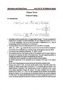
T = ( l , 5,7.0,7,9,9,8,1,2.3,3,2) 8=(5.6,5.4.8.8.9.6.3 0.4.2.0)
Fig. 1
Introduction
The channel routing problem is an important problem in VLSI/LSI layout design automation. In a channel routing problem, terminal locations at the top and bottom of a rectangle are specified, and netlists specifying the interconnection of terminals are given. A number from 0 to n is assigned to each terminal. A net i is a collection of vertical and horizontal wire segments that electrically connect a set of terminals with the same number i, while those terminals with number 0 are unconnected. The channel routing will connect the pins of nets on parallel sides of a rectangle channel. The goals of channel routing are to minimise the channel width and the via usage needed in the routing. A netlist description is defined by the top and bottom lists T = (TI, T2, . . ., T”, and B = (Bl, B , , . . ., B J . (or Bi)is the net number of a terminal at the top (or bottom) in the ith column. An example of a netlist description is shown in Fig. 1. The channel width, which is the number of horizontal tracks used, is bounded by a parameter called maximum channel density, denoted as d,, , that refers to the maximum number of nets crossing over any column. A via is a feed-through hole or a contact where
7
1
Netlist description
a
b
Fig. 2 a Intersection of two wire segments
b Overlap of two wire segments
There are two kinds of channel routing. One is restrictive routing, and the other is doglegging routing. The restrictive routing aims for a dogleg-free solution where the number of horizontal tracks on which any net can be positioned is limited to one. In this case any net is routed as a single horizontal segment with vertical branches connecting it to the terminals. The aim of restrictive routing is to determine a horizontal track number for every net. Another kind of routing is doglegging routing. The idea is to remove the constraint of restrictive routing on wire geometry, i.e. to allow net splitting between different tracks. The splitting vertical wire between different horizontal tracks is called dogleg. The introduction of doglegs may decrease the horizontal tracks needed in a channel. However, there are certain penalties to pay for this gain. Each dogleg adds one or two additional vias and this decreases the circuit performance from the electrical standpoint. Two-layer channel routers were presented in References 1, 2, 3 and 4. They only aimed for the dogleg solutions with minimum tracks used and did not concern the vias minimisation in the routings. In the most current technologies, three layers are available for routing. Four modes, VHV, HVH, overlap, and knock-knee modes, are 229
assumed in the three-layer restrictive channel routing algorithms [S-81. These algorithms produced a large number of vias, although they could obtain optimal solutions for channel width. The algorithm presented in Reference 9 was allowed the doglegs in the routing. Note that the number of tracks needed in a channel for the solution of doglegging routing can be reduced. However, the doglegging routing generates more vias in its solution. From a technological point of view, the number of vias sould be kept small. In IC processing, an increase of vias will cause a decrease of yield, which will affect the circuit performance significantly because of the resitance associated with vias. In addition, the increase in vias will cause an increase in routing space such that the manufacturing cost will be increased. Hence we consider the restrictive routing in this paper, and the via minimisation will also be considered in the routing algorithms. Previous routers were only considered the track locations of nets when the layering model was fixed, and such that the number of vias introduced in the routing were not important. Delayed layering in our channel routing is an efficient way to minimise via introductions and maximise the use of a preferred routing layer under the routability of each net guaranteed. Our proposed algorithm is divided into two steps : track assignment and layer assignment. The track assignment determines the horizontal track number of each net. A solution called transient layout will result from the track assignment. The transient layout is an incomplete or layerless physical layout in which the topology of nets in the layout has become clear, whereas the wire segments in the layout have not yet been assigned to layers. The layer assignment is to determine which layers can be used for routing the wire segments in the transient layout so that the vias generated are as small as possible. For the routing problem given in Fig. 1, the layout shown in Fig. 3a is a transient layout in which the horizontal track number of every net is determined. Fig. 3b is a complete physical layout with one via only. 1
5
5
5
6
5
7
0
4
7
8
9
8
9
8
1
2
3
3
2
9
6
3
0
4
2
0
9
8
1
2
3
3
2
Let Liand Ridenote a column number of the leftmost and the rightmost terminals for a net i, respectively. The x-interval of a net i is defined by (Li, Ri),and the x-length of a net is the number of columns in its x-interval. Both nets are in horizontal conflict if their x-intervals overlap. There are two cases for non-conlflict in the x-intervals of two nets i and j, as indicated in Fig. 4. The HCG can be ti-Ri
L-jRj wRi
Fig. 4
L-jRj
Lj
L-iRi b.Rj Li
Non-conjict on x-intervals oftwo nets
constructed as follows. Each vertex in the HCG represents a net. An edge is connected at vertices i and j, denoted by (i, j), if Ri< Lj or R j < Li,while both nets i and j are denoted by (Li, Ri)and ( L j , Rj), respectively. The graph in Fig. 5 is a HCG of netlist as given in Fig. 1. The edge (i, j) in HCG indicates that two x-intervals of net i and net j are not overlapping each other. Hence, two nets can be put into the same track if and only if their corresponding vertices are connected in HCG.
Fig. 5
Horizontal constraint graph
It is easy to see that any two nets must not overlap in a vertical column. A binary relation will be induced from the netlist. This relation, first defined in Reference 1, can be represented by a directed graph VCG where each vertex corresponds a net and a directed edge is connected from vertex i to vertex j , denoted by i +j or (i, j), if & = i and B, = j , 1 < k < n. The VCG of the netlist in Fig. 1 is demonstrated in Fig. 6. The number of vertices in the longest path of VCG is referred to as v M x . The definitions and properties associated with VCG are listed below.
a 1
5
7
.~
0
7
9
----
I
_ _ - - - _. _ ___ .5
6
5
4
8
8
9
6
-
-7- - 1-
4
_ - - . _ I _
3
0
4
2
0
b Fig. 3
Layout
a Transient
Fig. 6
Vertical constraint graph
b Complete
2
Graph models of the channel routing problem
It must be guaranteed that no two wire segments running in different directions are run on the same layer. Both graphs, (vertical constraint graph (VCG) and horizontal constraint graph (HCG)) are used to avoid the vertical and horizontal conflicts among the nets, respectively. 230
Definition 1 : Vertex i in VCG is a predecessor of vertex j, if and only if there is a directed path from vertex i to vertex j .
Property: The properties of VCG (denoted as G)are: 1. The precedence relation in G is transitive. In other words, j is a predecessor of m, if and only if j + k and k + m. IEE PROCEEDINGS, Vol. 137, Pt. E, No. 4, JULY 1990
2. The precedence relation in G is irreflexive. In other words, a directed path from vertex k to vertex j is not in G if and only if there is a directed path from vertex j to vertex k in G.
DeJinition 2: A precedence relation which is both transitive and irreflexive is a partial order or topological order. The order information of nets will be derived from VCG if we route every net from the top track to the bottom track in the channel. The net i will be routed preceding the net j if there is a directed path from vertex i to vertex j in VCG. According to definition 2, the order sequence of nets in VCG is a topological order. The horizontal track number of each net can be decided based on this topological order. However, there are many orders determined by the VCG and each order will produce a possible solution. Therefore, a straightforward way of track assignment is to use a topological sorting to enumerate all orders in the VCG and to find one optimal solution amonst them. 3
Topological order of the track assignment
Note that any two nets can be put in the same track if and only if their corresponding vertices are connected in HCG. Each maximal clique (or complete subgraph) in HCG forms a group of nets which can be routed in the same track. HCG is used to determine how nets can be broken into some groups. To avoid the vertical conflicting in the routing, only nets with corresponding vertices that have no predecessors in VCG should form a subgraph of HCG and be partitioned into some groups by finding the maximal cliques in the subgraph. Nets in each group are order independent because they have no vertical conflict in VCG. Hence, the group is defined as an independent class of nets. Because at most two layers are needed for routing the horizontal wire segments and the remaining layer is preserved for vertical wire segments, two independent classes can be produced simultaneously at each time. The algorithm to determine the topological order proceeds by selecting out two independent classes with vertices in VCG that have no predecessors. Then, vertices in the two independent classes together with all edges leading out from them are deleted from VCG. These two steps are repeated until all vertices have been listed. Let V, be a set of vertices which have no predecessors in VCG. This algorithm can be written as following. ALGORITHM # I 1. input VCG. Let n be the number of vertices 2. while ( I V, I # 0) 3. partition the vertices in V, into independent classes E by finding all maximal cliques in a subgraph of HCG with corresponding vertices in V,; 4. output two classes Ai and A i + from E ; 5. delete all vertices in Ai and A i + , and all edges leading out of them from VCG; 6. V, = a set of vertices which have no predecessors in the reduced VCG. 7. end E N D ALGORITHM # I
,
The solution for track assignment is to find a topological order of independent classes such that the number of classes in the sequence is minimised. The number of classes is proportional to the number of tracks used in a IEE PROCEEDINGS, Vol. 137, Pt. E, No. 4, J U L Y 1990
channel. Based on the sequence, the track assigned to nets in each class can be determined. Let A , , A , , ..., and A, be a topological order of independent classes. Both classes A,i- and A,i are generated at i-th iteration in the algorithm and nets in classes A z i - and A Z iare routed in the track i at two horizontal layers, respectively. It is clearly shown that only one independent class may be generated at the iteration when all vertices in V, form only one maximal clique in HCG. If the set of vertices in V, forms a unique maximal clique in HCG at the i-th iteration, the generated classes will be = V, and A,i = 0, where 0 is a null set. The relation between the number of iterations in the modified algorithm and the channel width of routing problem is described by Lemma 1.
,
Lemma I: Let { A l , A,, . . .,A,,,} be a topological order of independent classes. The channel width for three-layer routing problem equals m/2. Proof: Two independent classes are generated at each iteration. The nets in one independent class will be assigned to first horizontal layer and the other for second horizontal layer on the same track. Therefore, the number of independent classes is proportional to both the channel width of three-layer routing problem and the number of iterations in the algorithm # 1.
It is noted that the low bound of channel width, denoted as w, for the three-layer restrictive routing is max (rdmX/21,umX) since at most two layers can be used to route the horizontal wire segments. The optimal solution to three-layer restrictive channel routing problem is to find a topological order of independent classes { A , , A , , .. ., A,,,} such that m = 2 0 and nets in the class Ai and A i + l are assigned to ri/21-th track on two horizontal layers, respectively. Let Ai be the longest path length from vertex i in VCG to the vertex which has no successors, and Si be the dynamic local density of net i. The dynamic local density of net i is defined to be the maximal number of nets which have not been assigned to tracks and are overlapping each other in x-interval of net i. It is clear to show that the algorithm requires at least max (Ai, r6J27) iterations to finish the routing problem since the independent class, which contains the net i, was generated. To prove that the sequence of independent classes is an optimal partial order, the following theorem is required. Theorem I: The sequence { A l , A , , ...,A,,,} is an optimal partial order of independent classes if the sequence follows the condition which is defined as o - r.j/21 2 max (Ai, rSJ21) for each net i in class Ai.
(1)
Proof: The net i in the class A j is generated at the rj/21-th iteration. It is clear to show that the number of iterations needed for the completion of the algorithm is at least max (Ai, rSJ21) after the net i was routed in the rj/21-th track. Lemma 1 shows that the channel width needed in the routing problem equals the number of iterations in the algorithm. If the low bound of channel width is o,we have and it proves that 23 1
The channel routing is a well known NP-complete problem [13]. Therefore, we conjecture that the determination of optimal partial order of independent classes is an NP-complete problem. A heuristic algorithm is presented. In the proposed algorithm, every vertex in HCG is weighted by a cost, and each time two independent classes with maximum weights are selected first. The cost estimated on all vertices in HCG does not only involve the x-length of corresponding net but also consider its longest path length and dynamic local density of the net. The cost F.of net i in the independent class Ai is evaluated as follows.
to the tail of list which is pointed by the headnode i. In the case of a directed graph with n vertices and e edges, this representation requires n headnodes and e list nodes. For VCG as shown in Fig. 6, the adjacency list is indicated in Fig. 8. count link
x-length of net i if 2 0 - j > max ( 2 4 , Si) if 2 0 -j = max ( 2 4 , Si) (2)
K=L
The cost of Ai is the summation of cost of all nets in it.
A net with cost p is called dominant net. The p is a dominant cost and forces the independent class which contains the dominant net to be selected first. Consider the netlist as shown in Fig. 1, the process on determination of partial order of independent classes for the track assignment is presented in Fig. 7 and its corresponding transient layout is demonstrated in Fig. 3a. reduced VCG
vf
subgraph of HCG wlth vefttces Vf
- - - - - - - - - - - - - - - - - - - - - - - - - - - -- -
.
'9 1
Al=[7,9] A2.111
2 . 4
.
e
.
2 . 4 6
2-6
A5=[2,6] A6= I.4J
Fig. 7
4
Steps in determining independent sets
Topological sorting algorithm
In the track assignment, the topological order of independent classes will be generated based on HCG and VCG. The algorithm to determine the topological order is called topological sorting in VCG. After the determination of topological order, each net can be assigned to a track in the channel based on the predetermined order. Nets in an independent class are assigned to same track. Hence, the number of classes in the topological sequence decides the number of tracks needed. In this section, we concentrate on the discussion of topological sorting algorithm. First, the data structure used in the algorithm is introduced, and the algorithm is then explained. The algorithm assumes that VCG is represented by the adjacency list. The adjacency list for VCG is represented as n linked lists while there are n vertices and e edges in VCG. Each list includes both a headnode and list nodes. The headnodes of these lists represent vertices in VCG and contain two fields: C O U N T and L I N K . The C O U N T field contains the in-degree of that vertex and the L I N K field is a pointer to the first node in the adjacency list. Each list node contains both V E R T E X and L I N K fields. The V E R T E X field records the index of vertex in VCG and the L I N K field is a pointer to next node in the linked list. The adjacency list for VCG is easy to be set up at the time of input. The C O U N T field of headnode j is incremented by one when an edge (i, j ) is in VCG, and the node with V E R T E X field containing index j is linked 232
Fig. 8
Adjacency list of V C G
From observation of the adjacency list, we known that the headnode j with zero count corresponds to a vertex which has no predecessors. The vertices with zero count are maintained in a queue Q. We present the topological sorting algorithm as shown in the following. ALGOR1 T H M T-SOR T 1. input VCG and set up the adjacency list; 2. for i = 1 to n do/* put all vertices with zero count into Q */ if C O U N T ( i ) = 0 then put vertex i into Q; 3. 4. end 5. while Q is not empty do 6. set up a subgraph G with vertices in Q from HCG; output two independent classes Ai and A i , which 7. are two maximal cliques with maximal cost in G, in the topological sequence ; for each vertex k in Ai or A j do 8. 9. ptr.+ L I M K (k); 10. whde ptr # 0 do 11. m t VERTEXbtr); C O U N T ( m )c C O U N T ( m ) - 1; 12. if C O U N T ( m ) = 0 then put vertex m into Q; 13. 14. end 15. end 16. end END ALGORITHM T-SORT
Line 7 in the algorithm T-SORT is to determine two maximal cliques of the subgraph with vertices in Q. Since it is essential, we first explain it below. Because there is a weight assigned in each vertex in HCG, our problem is to determine the maximum weighted clique in the subgraph of HCG. In general, to find maximum weighted clique in graph is an NP-complete problem [ll]. However, the problem becomes tractable when the graph is restricted to comparability graph. First, we define the comparability graph as follows. Definition 3 [12]: Each edge can be assigned a one-way direction in such a way that the resulting oriented graph ( V , F) satisfies the following transitive condition:
(a, b)
E
F and
(b, c) E F imply
(a, c)
E
F
(for all a, b, c
E
V)
I E E PROCEEDINGS, Vol. 137, Pt. E, No. 4, J U L Y 1990
An undirected graph which is transitively orientable is called a comparability graph.
Theorem 2: The horizontal constraint graph is comparability graph. Proof: Let two x-intervals of nets i and j be denoted as Zi = ( L , , R,) and Z j = ( L j , Rj). I , < Z j means that Ri< L j or the x-interval Zi lies entirely to the left of x-interval Z j . Define an orientation F of HCG as follows: ( i , j ) E F o Z , < Z j for all i , j Clearly, the transitive condition is satsified since I , < Zj < Z, implies ZiZ,. Thus F is a transitive orientation of HCG.
Theorem 3 [12]: The time complexity of maximum weight clique in the comparability graph G, = (V,, E,) is O( I vc I ). Theorem 4 : In the case of VCG with n vertices and e edges, the complexity of algorithm T-SORT is O(n + e). Proof: For the algorithm T-SORT, the loop of lines 2 4 takes O(n) time. The while loop of lines 5-16 takes w iterations over entire program as explained in Lemma 1, where w is channel width. In this while loop, two tasks, which are clique determination on line 7 and queue creation in for-loop of lines 8-15, are critical. The for-loop of lines 8-15 takes time order O(di)for each vertex i, where di is out-degree of vertex i. Since this loop is encountered once for each vertex output, the total time for this part of algorithm is O(C di)= O(e)for 1 6 i < n. The time for clique determination is O ( c ni)= O(n) for 1 < i < w known from Theorem 3, where n, is the number of vertices in V, at the i-th iteration and n is the number of vertices in HCG and also is the number of vertices in VCG. Hence, the time of while-loop of lines 5-18 is O(n + e), and the complexity of topological sorting is O(n + e + n) = O(n + e). 5
Algorithm for layer assignment
The layer assignment assigns every wire segment in the transient layout which results from the track assignment with a layer such that the physical layout is completed with the minimum number of vias. The point where the horizontal wire segment and vertical wire segment of a net are connected in the transient layout is called the via candidate, since the point will be a real via when wire segments connected to it are located at different layers. Therefore, the layer assignment is to determine which layers can be used for routing the wire segments in the transient layout so that the via candidates which are going to be real vias can be minimised. The transient layout can be represented as a graph called SegmentCrossing Graph (SCG) which is denoted as G, = ( V , , E, U E,). The graph is constructed as follows. Each vertex in V , represents a wire segment in the transient layout. The edges in G, are divided into two sets which are the set of via-edges (denoted as E,) and the set of cross-edges (denoted as E,). If two wire segments are connected by a via candidate, an edge in E, will connect these two corresponding vertices in SCG. An edge in E,, which is connected two vertices in SCG, means two corresponding wire segments are cross over each other. We use dashed lines and solid lines for two different kinds of IEE PROCEEDINGS, Vol. 137, Pt. E, N O .4, JULY 1990
v3
s5 Is4 I
ICS
v 5 h c13 c4 j v7 Islo sll ;8 I
1v6 s2 ~ 9 1 ~ 1 0 v4
I
m
I
-
s3 I
c10). G, = ( K , E, U E,) can be divided into two subgraphs, which are G: = ( V , , E,) and G,"= (K, E,). The subgraph G: is to relate the crossing between wire segments, and the subgraph G,"is to indicate the interconnection of nets. Each edge in G,U represents a via candidate. Each connected component in G," means the interconnection of a net in the layout. For a vertex u E V , , both sets of vertices are adjacent to it. For distinguishing between them, we define a set of vertices, which are adjacent to u by the edges in E,, to be an adjacent list of u, and the other set of vertices which are connected to u by the edges in E, is defined as a cluster of U. The adjacent list and the cluster of vertex u are denoted as A(u) and C(u), respectively. For SCG as shown in Fig. 10, two sets of the vertex s2 are A(s2) = {sl, s3) and C(s2) = {s6, s7, s8, s9, s12).
0-
v3
s4
s10 v7
Fig. 10
Sll
vLI
s12
Segment-crossing graph
Let layers in three-layer routing be represented by colours 0, 1 and 2, respectively. The layer assignment problem of the three-layer transient routing can be translated to a 3-colourable problem of G,. The layer assignment of wire segments in the transient layout is to assign all vertices in the colourless graph G, with colours when two vertices, which are connected by an edge in E,, are painted by different colours, and such that two vertices, which are connected by an edge in E,, are painted as near the same colour as possible. In other words, a colur painted on the vertex u is different from the colours assigned to the vertices in C(u) and is as similar to the colours assigned to the vertices in A(#) as possiible. For instance, the graph SCG give in Fig. 10 can be coloured as shown in Fig. 11. Fig. 11 shows that all via candidates except 06 do not change into real vias. The final layout with only one via is completed as presented in Fig. 12. A heuristic algorithm for layer assignment is proposed in this section. Let us first consider the basic concept in s9
0
s7
v3
bs4
Fig. 11
Colour assignment on the segment-crossing graph
233
the algorithm. The colours assigned to the vertices in A(u) are the recommended colours of vertex U. If the vertex U is coloured with one of the recommended colours, some 1 D
1
s'
154 I
2
Fig. 12
3
4
I
I
I
I
s12
s7 s5
I
s10
2
I
5. Calculate c(i) by c(i) = c(i) U a(u), for all i E C(u). 6. Repeat steps 2-5 until all vertices in G, are active vertices.
?"6
SB
c-ylr-'I
s91 3
I
4
S6
S2
I
j s3 m
1
Physical routing
- layer 0 or colour 0 _ _ _ _ layer 1 or colour 1 ------- layer 2 or colour 2
via candidates connected to the wire segment which corresponds to U can be eliminated. The elimination of a via candidate means the wire segments connected to it are routed on same layer such that a real via is not created. The colours assigned to the vertices in C(u) are the constrained colours of vertex U. The constrained colour represents a colour to which the vertex U cannot be assigned for avoidance of violating the layout requirement. Therefore, the expected colours of vertex U to eliminate the via candidates are the colours which belong to the recommended colours of vertex U but not the constrained colours of vertex U. For formulating the heuristic algorithm, some definitions associated with each vertex in V , are needed. Let n be the number of vertices in V,. The definitions are listed as follows. Definition 4 : A colour that has been assigned to a vertex U is called an active colour of U denoted as 4u). The vertex U that has assigned a colour is called an active vertex, and it is called an inactive vertex if it has not been assigned a colour. Definition 5 : The recommended colours of a vertex U, which is denoted as r(u), are the colours that have been assigned to the vertices in A(u).The r(u) can be calculated as following: r(u) = {u(i)I 1