ACCAT 2006
A Diagrammatic Logic for Object-Oriented Visual Modeling Zinovy Diskin
1,2
Department of Computer Sceince University of Toronto, Canada
Uwe Wolter3,4 Department of Informatics University of Bergen, Norway
Abstract Generalized sketches is a graph-based specification format that borrows its main ideas from both categorical and first-order logic, and adapts them to software engineering needs. In the engineering jargon, it is a modeling language design pattern that combines mathematical rigor and appealing graphical appearance. The paper presents a careful motivation and justification of the applicability of generalized sketches for formalizing practical modeling notations. According to the needs in practical modeling we extend the sketch formalism by dependencies and developed new semantic notions based on the Instances-as-typed-structures idea. We show that this new framework fits in the general institutional pattern of logic management [14,17] and is well amenable to algebraic manipulations of categorical meta-logic. Keywords: diagrammatic modeling, model management, generic logic, categorical logic, diagram predicate, categorical sketch
1
Introduction
People like drawing pictures to explain something to others or to themselves. When they do it for software system design, they call these pictures diagrams or diagrammatic models and the very notation for them a modeling language. Syntax of diagrams is accurately specified in the so called metamodel but the intended meaning or semantics of diagrammatic constructs often remains intuitive and approximate. Sometimes it is so fuzzy that the construct becomes close to be meaningless at all, in which case the experts advise to consider it as a modeling placebo [23]). Until 1
Email:
[email protected] Supported by OCE Centre for Communications and Information Technology, IBM CAS Ottawa and IBM Eclipse Innovation Grant 3 Email:
[email protected] 4 Research partially supported by the Norwegian NFR project SHIP/VERDIKT. 2
This paper is electronically published in Electronic Notes in Theoretical Computer Science URL: www.elsevier.nl/locate/entcs
Diskin and Wolter
recently, this state of the art did not bother the modeling community too much: diagrammatic models were mainly used as a communication medium between business experts, software designers and programmers, and their precision was (although desirable) not a must. The situation has dramatically changed a few years ago with the rapid invasion of the model-centric trends in software industry. Model-Driven Engineering (MDE), Model-Driven Development (MDD), Model-Driven Architecture (MDA) are different names of basically the same movement aimed at making models rather than code the primary artifacts of software development with code to be generated directly from models [24]. Needless to say that for MDD, having a precise formal semantics for diagrammatic notations is extremely important. The industrial demand greatly energized building formal semantics for diagrammatic languages in use, and an overwhelming amount of them was proposed. A majority of them employ the familiar first-order (FO) or similar logical systems based on string-based formulas and result in bulky and somewhat unwieldy specifications. It is caused by the unfortunate mismatch between the string-based logical machineries and the internal logics of the domains to be formalized. Roughly, the latter are conceptually two-dimensional (graph-based) and class-oriented (are “sortwise”) while the former are string-based and element-oriented (are “elementwise”). In the next section we discuss these problems in more detail and argue that the machinery of the so called generalized sketches proposed in [21,7,12], or the Diagram Predicate logic (DP-logic) offers just that apparatus which industry needs because it is inherently sortwise and graph-based (see also the discussion in [9]). We believe that as soon as modeling, meta-modeling and modeling language design are becoming common tasks in software industry, DP-logic may become a practical logic for diagrammatic modeling in software engineering. That is why a clear presentation of DP-logic suitable for an engineer becomes an important task. This paper has three main goals. (a) The first is to motivate the applicability of the DP-logic pattern for formalizing practical diagrammatic notations used in software modeling. We show that generalized (rather than classical categorical) sketches appear on the scene quite naturally. In addition, it is very convenient to record some logical rules right in the signature of predicate symbols by introducing dependencies between the predicates [28]. (b) The second is to carefully define and explain this pattern in a way close to how a software engineer thinks of diagrammatic modeling. Particularly, it is important to “switch” from viewing semantics as a structure-preserving mapping from a specification to some predefined universe (the indexed view as it is customary in categorical logic) to the dual view of semantics as a structure-preserving mapping to a specification (the fibrational view). This is nothing but the idea of typing, which is ubiquitous in software engineering, and we will refer to this semantics as IATS (Instances As Typed Structures) (see [10] for the role of IATS in database metadata management). Mathematically, this switch is a special instance of the well-known duality between indexed and fibred categories. As for the syntactic side of DP-logic, we tried to present it in a way parallel to how the syntactic basics of the ordinary FOL are usually presented. A corner-stone 2
Diskin and Wolter
of this parallelism is a simple observation that a labeled diagram is nothing but a graph-based analog of a formula. More accurately, the notion of labeled diagram is quite generic and an ordinary logical formula P (x1 ...xn ) is just a specific syntax for a labeled diagram whose shape is the arity set α(P ) of predicate P and the list x1 ...xn encodes a mapping from α(P ) to the set of variables used for building formulas. Then the notion of sketch naturally appears as a set of graph-based atomic formulas over a fixed context of names (variables). Table 1 below presents this parallel and other parallels. (c) Building DP-logic along the lines of (a,b) leads to a (quite natural yet) somewhat unusual logical formalism. It is not clear a priori whether it fits in the standard framework for “logic management” offered by the institution theory [17]. Thus, our third goal is to investigate whether DP-logic gives rise to an institution. In the IATS semantics, forgetful functors are defined by pullbacks and semantics becomes functorial only “up to isomorphisms”. That is, in the fibred semantics setting, we cannot expect more than that the forgetful functors between categories of models constitute an overall lax (or pseudo) “model functor”. We will indeed show that DP-logic provides a pseudo institution, in this sense, for any fixed signature of diagram predicates Π. We will also show that Π-sketches and their instance semantics form a lax specification frame [14]. In more detail, the contents of the paper is as follows. In section 2 we carefully motivate every essential feature of the machinery we are going to define: what are the benefits of classical categorical sketches, why we need their modification to generalized sketches, and why it is convenient to introduce dependencies between predicate symbols. In addition, we argue for IATS semantics as opposed to indexed semantics. In section 3 we first consider and discuss two simple examples of modeling with sketches, and then (subsection 3.2) discuss how to specify systems of models/sketches in the institution framework. These two sections aim mainly at goals (a) and (b). Section 4 presents a framework of accurate definitions and immediate results based on them, and culminates in Theorem 4.16, essentially stating the main result described in (c) above.
2
A quest for logic convenient for diagrammatic modeling
2.1
Categorical sketches vs. first-order logic.
A key feature of universes modeled in software engineering is their fundamental conceptual two-dimensionality (further referred to as 2D): entities and relationships, objects and links, states and transitions, events and messages, agents and interactions; the row can be prolonged. 5 Each of these conceptual arrangements is quite naturally represented by a graph – a 2D-structure of nodes and edges; the latter are usually directed and appear as arrows. In addition, these 2D-structures capture/model different aspects of the same whole system and hence are somehow interrelated between themselves. (For example, events happen to objects when the latter send and receive messages over dynamic links connecting them. These events 5
We are indebted to Bran Selic for bringing the conceptual two-dimensionality metaphor onto the stage.
3
Diskin and Wolter
[=] [limit]
property
H×P
Ownership
in
date id
Oship
Oship
Date
own dd
id
[cover]
date
Person
Person
•
mm yy Integer House
id
in H×P
in
pro
Oship
[limit]
House
[key] Oship
id
Date
date
[limit] dd mm • yy
owner Person
[integer]
pro
pro
House
House
property
Oship [limit] Oship House [colimit] House
(a1) ER-diagram
owns
pro
[=]
o
dd mm yy
owner
House
p
House
owns
House
0..*
owns isOwned
isOwned 1 Person
[limit]
[inverse] owner
Person
id
Person
isOwned [1] Person
(a2) UML class diagram (a) Engineering data models
(b) Classical sketch specification (b1 and b2)
(c) Generalized sketches (c1 and c2)
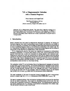
Fig. 1. A sample of sketching diagrammatic notations
trigger transitions over objects, which change their states). Thus, we come to another graph-based structure on the metalevel: nodes are graphs that model different aspects of the system and arrows are relations and interactions between them. The specificational system of aspects, views and refinements can be quite involved and results in a conceptually multi-dimensional structure. However complicated it may seem, this is the reality modern software engineers are dealing with (and languages like UML try to specify). Describing this multidimensional universe in terms of FO or similar logics, which are based on string-based formulas talking about elements of the domains rather than their relationships, flattens the multi-level structure and hides the connections between the levels. This results in bulky and unwieldy specifications, which are difficult (if at all possible) to understand, validate, and use. A radically different approach to specifying structures, which focuses on relationships between domains rather then their internal contents and is essentially graphbased, was found in category theory (CT). It was originated by Charles Ehresmann in the 60s, who invented the so called sketches (see [26] for a survey); later sketches were promoted for applications in computer science by Barr and Wells [2] and applied to data modeling problems by Johnson and Rosebrugh [19]. The essence of the classical sketch approach to specifying data is demonstrated by Fig. 1. Figure 1(a1) shows a simple ER-diagram, whose meaning is clear from the names 4
Diskin and Wolter
of its elements: we have a binary relation O(wner)ship over the sets House and Person, which also has an attribute date. In addition, the double frame of the node House denotes a so called weak entity [25]: there are no House-objects besides those participating in the relationship. A sample of another notation for data modeling, the now widely spread UML class diagrams, is shown in Fig. 1(a2). The edge between classes House and Person is called an association; labels 0..* and 1..* near association ends are multiplicity constraints. They say that a Person(-object) can own any number of House-s including zero, and any House is owned by exactly one Person. Evidently, data described by models can be seen as a configuration of sets and mappings between them. In the classical Ehresmann’s sketch framework, this can be specified as shown in column (b) of Fig. 1. The upper sketch (b1) graphically consists of three pieces (above and below the dashed line) but actually consists of the carrier graph (the graph above the line) and a few labeled diagrams. The label “limit” is hung on the arrow span (H × P, p, o) (note the double arc) and declares the span to possess a special limit property. This property makes the set H × P the Cartesian product of House and Person (see, e.g., [2] for details). Similarly, the set Date is declared to be the Cartesian cube of the set Integer of natural numbers. Two additional diagrams below the dashed line force the arrows in and pro to be, respectively, injective and surjective by standard categorical arguments [2]. Particularly, it implies that the set Oship is a subset of Cartesian product and hence is a relation. In other words, an Oship-object is uniquely determined by a House-object and a Person-object. Finally, two labels [=] declare the corresponding diagrams of mappings to be commutative so that mappings pro and own are indeed projections of the relation Oship. For the lower sketch (b2), the label “limit” declares the set owns with two projections to be the graph of mapping isOwned. This is basically the meaning of the UML diagram (a2): mapping isOwned is total and single-valued (the default property of arrows in column (b)) while mapping owns is a relation inverse to isOwned. The limit and colimit predicates are amongst the family of the so called universal properties of sets-and-mappings diagrams found in CT. This family of predicates, though compact, is extremely expressive and allows us to specify arbitrary properties of arbitrary sets-and-mappings configurations. 6 Particularly, if the configuration in question specifies semantics of a diagrammatic model D (say, a ER or UML diagram), the corresponding sketch S(D) appears as a precise formal yet graphical analog of D. We will call this procedure sketching the diagrammatic models. It provides a powerful mathematical framework for formalization and analysis of their semantics, see for example [19,22] for several useful results about ER-diagrams. 2.2
Why generalized sketches?
Although mathematically elegant, the classical sketch approach has several inherent drawbacks in engineering applications. For instance, in order to declare a simple fact that O(wner)ship is a binary relation, we were forced to introduce a few auxiliary 6
In fact, since formal set theories can be encoded by universal predicates (by mapping them into toposes [20]), we can say that any formalizable property of sets-and-mappings configurations can be expressed by universal diagram predicates and thus represented in the sketch language.
5
Diskin and Wolter
elements into our specification. A similar complication occurred for specifying a simple surjectivity property. Note also that while extensions of nodes House and Person are to be stored in the database implementing the specification, extension of node H × P is (fortunately!) not stored. Similarly, classical sketch (b2) looks much more complicated than the original UML diagram. Thus, before we assign a precise semantic meaning to ER- or UML-diagrams, we need to apply to them some non-trivial transformations, and only after that the patterns of categorical logic can be used. From the view point of a software engineer, these transformations look artificial, unnecessary, and misleading. Fortunately, the deficiency of the classical sketch framework mentioned above can be fixed while preserving the benefits that algebraic logic brings to the subject. The idea is demonstrated in column (c) of Fig. 1. Consider the upper specification (c1). We still want to specify the type of O(wner)ship-elements externally via mappings rather than internally (as is done in FOL), but we do not want to introduce the Cartesian product H × P into the specification. The crucial observation that allows us to accomplish the task is well-known: for a given span of mappings, e.g., O = (Oship, property, owner), its head Oship is isomorphic to a relation iff the legs (projection mappings) possess a special property of being jointly injective or jointly monic The latter means that for any two different objects of type Oship, at least one of the leg mappings gives two different values (see [16] for details of an abstract formulation). This property of a family of mappings/attributes is well known in database theory under the name of key. Thus, we declare the span O to be a key and come to the specification shown in Fig. 1(c1). Note also that label [Integer] is not the name of the node but a predicate label declaring the extension of the node to be the set of integers. Thus, the specification in Fig. 1(c1) presents a graph G, in which four diagrams are marked by predicate labels taken from a predefined signature. If Π denotes the pre-defined signature, we will call such specifications generalized Π-sketches or just (Π-)sketches. Semantic meaning of such a sketch can be given by a graph morphism [[ ... ]] : G → Set into the graph Set of sets and mappings, which is compatible with the predicate labels in the sense outlined above. For example, the span ([[ property ]],[[ owner ]]) is a key. Similarly, specification (c2) presents another graph G with two labeled diagrams: arrow isOwned is labeled with its multiplicity constraint, and the pair of arrows is labeled with predicate [inverse] declaring the corresponding mappings to be mutually inverse. Semantics if such specification is given by a graph morphism [[ ... ]] : G → Rel into the graph Rel of sets and partial multi-valued mappings (binary relations), which is compatible with the predicate labels. That is, mapping [[ isOwned ]] is totally defined and single-valued (because of the multiplicity [1]) and mapping [[ owns ]] is inverse to it. From now on, the term sketch will mean generalized sketch, that is, a graph-based object endowed with diagrams labeled by predicate symbols. 2.3
Semantics for generalized sketches, engineeringly
The passage from classical to generalized sketches does not finish our quest for specification machinery suitable for the modern software modeling. The point is that viewing semantics of a sketch as a mapping into Set or Rel or another semantic universe is not customary for a software engineer. In more detail, this view works 6
Diskin and Wolter
well for the value-type part of the model, in our example, the part consisting of nodes Integer and Date and arrows between them. The primitive types (Integer in our case) have a special predefined semantics, and it has a fixed implementation in the computer system. The situation with the class part of the models (the Oship-span in our example) is different. This part can be considered as a UML class diagram G with a span of directed associations, see Fig. 2(b) and disregard the labels for a while. UML defines a semantic instance of a class diagram to be a graph O of objects (nodes) and links (arrows) between them, which are typed/classified by class and association names respectively, see Fig. 2(c-column), where type labels are shown after colon (and in violet with a color display). Mathematically, labeling amounts to a graph mapping τ : O → G with G being the graph presenting the class diagram, which must satisfy diagram predicates attached to G. Note that by inverting the mapping τ we come to mapping G → Rel rather than Set. Indeed, if f : A → B is an arrow in graph G, the set of arrows τ −1 (f ) in O represents, in general, a relation between the sets of nodes τ −1 (A) and τ −1 (B) in O rather than a single-valued mapping between them (see, for example, the top instance in Fig. 2(c2)). Semantics as IATS (Instances As Typed Structures) is ubiquitous in software engineering. For a software engineer it is customary to think of an instance of a model G (a graph or another structure) as a structure O similar to G, which amounts to a structure preserving mapping τ : O → G. Note also an unfortunate linguistic mismatch with use of the term “model”. In software engineering, a model normally refers to a syntactic concept while a corresponding semantic concept is called a model’s instance. In mathematical logic, syntactic constructs are normally called specifications or theories while models are their semantic counterparts, “a model of a theory”. In the paper we will use, from now on, the terms models and instance in the engineering sense.
2.4
Dependencies (arrows) between predicate symbols
For the relational interpretation of arrows, being a single-valued or/and a totally defined relation become special properties to be explicitly declared rather than taken for granted like in the Set-valued semantics. Hence, we need to include the corresponding predicates into our signatures for everyday modeling. However, singlevalued and total mappings still play a special role, and some diagram predicates like, e.g., [key], assume that all the participating arrows are such. In other words, if a span is declared to be a key, all its legs are automatically assumed satisfying the predicates of being single-valued and total. We say that there are dependencies [key] ` [total] and [key] ` [s-valued]. Of course, less trivial dependencies between predicates are also possible. It follows then that a signature is a graph, whose nodes are predicate symbols and edges are dependencies between them. A simple example in Fig. 2(a) demonstrates the idea. The signature consists of three predicate symbols of arity shape “arrow” and one predicate symbol of arity “binary span”. In addition, there are four arrows ri , i = sk1, sk2, tk1, tk2 between the predicates, whose arities are mappings between the arity shapes. For example, the arrow rsk1 : [s-valued] → [key] denotes depen7
Diskin and Wolter
dency [key] `rsk1 [s-valued] and its arity α (rsk1 ) is the graph mapping sending the only arrow of [s-valued]’s arity to the left leg of [key]’s arity span. It means that if a span of arrows is declared to be a [key], then its left leg must satisfy the predicate [s-valued]. To ensure this for the right leg, we introduce another dependency [key] `rsk2 [s-valued] with arity mapping sending the arrow in [s-valued]’s arity to the right leg of [key]’s arity span. The same situation is for the predicate of being totally defined relation. Declaring a span of arrows in graph G as a [key], for example, means to define a graph mapping d : α [key] → G from the arity shape of [key] into G. The dependency [key] ` [s-valued] entails then that any declaration d : α [key] → G causes a corresponding declaration α(rsk1 ); d : α[s-valued] → G of an [s-valued] arrow. Note that, due to pre-composition, the direction of arity mapping becomes opposite to the direction of dependency. We have chosen here to formalize dependencies by arrows between predicate symbols going in the direction of arity mappings. A convenient mnemonics for this is to use a special arrow-head for arrows between predicate symbols as shown in Fig. 2(a). Thus, a signature is a graph (category) Π of predicate symbols and dependencies between them, which are endowed with arities: a graph α(P ) for a node/predicate P ∈ Π and a graph mapping α(r) : α(P ) → α(Q) for an arrow/dependency r : P Q. In the next section we will see an example of how such a signature could work.
3
Modeling via sketches.
In this section we first discuss two simple examples of modeling with sketches, each one using sketches over a different base category, Set and Graph, where the arities of predicate symbols live. Then, in subsection 3.2, we discuss how to specify systems of models in the sketch framework. 3.1
Two simple examples
First, we present a simple logic for “categorization of objects”, in which arities are sets. Then we continue the discussion of the first example in section 2, where arities are given by graphs. The reader may find it helpful to look at the upper part of Table 1 for reading this section. 3.1.1 Sketch logic over Set: Painting objects (or modeling for dummies :) A typical situation one encounters in software modeling is categorization of objects into classes or types. We have a set of objects O, a set of types T (which are just names/symbols) and a typing mapping τ : O → T . For example, if T consists of four labels red, blue, black, and white, then a typing mapping would classify the set of objects into “red”, “blue”, “black”, and “white” instances. In the modern jargon, the set {red, blue, black, white} is called the model and any mapping τ as above is its instance. So far, any mapping τ : O → {red, blue, black, white} is considered to be a legal instance of our model. Suppose however that by some business rule, the number of red objects must be always less than the number of blue objects, and the number 8
Diskin and Wolter
Graph-based logic
String-based logic
Diagrams/Formulas and Substitutions Arity shape of a predicate P , αP ∈ Graph
Arity set, αP ∈ Set. Elements of this set are usually named by natural numbers (which unfortunately brings ordering entirely irrelevant here)
Carrier object/structure, graph G ∈ Graph
Set of variables/context, Γ ⊂ Var ∈ Set
Structural element (node or arrow), e ∈ G
Variable, x ∈ Γ
Mapping of carriers, s : G → G0
Variable substitution, s : Γ → Γ0
Labeled diagram, G P (d), with d : αP → G
Atomic formula in a fixed context, Γ P (x), where x = x1 ...xn , i.e., x : αP → Γ
Π,G) Set of labeled diagrams over a carrier G, Fm(Π
Set of atomic formulas in a fixed context, Fm(Π,Γ)
Dependencies and Derivations P (a,b,c)
(Meta-)inference rule r : Q(b,b) with (metavariables) a, b, c ranging over Γ
Predicate dependency, r : Q P with arity substitution r α : αQ → αP Derivation/labeled sequent, r : Q(r α ; d)
P (d)
Labeled sequent P (x7 , x3 , x4 ) `r Q(x3 , x3 )
Graph of all labeled diagrams and all labeled Π,G) sequents over the carrier G, Fm Fm(Π
Graph of all atomic formulas and all labeled sequents in a fixed context Γ
Sketch = Structure + Constrains, G = (G, T ) Π,G) closed w.r.t. with T a subgraph of Fm Fm(Π derivations
Theory, Γ T or `Γ T , where T ⊂ Fm(Π, Γ) and is closed w.r.t. all applications of the inference rules
Table 1 String-based logics as “graph-based” logic based on sets rather than graphs: Syntax
of black objects is less than that of white ones. To specify this requirement, we first introduce into our specification language a binary predicate P , and then add to our model two predicate declaration or formulas P (red, blue) and P (black, white). In more detail, the predicate symbol P has the arity set consisting of two elements (placeholders), for example, 1 and 2, and a mapping ω : Ω → {1, 2} is considered to be compatible with P iff |ω −1 (1)| < |ω −1 (2)|. Formally, semantics of our predicate symbol P is the set [[ P ]] of ω’s satisfying the requirement. In the predicate declaration P (red, blue), the bracketed part denotes the mapping d : {1, 2} → T = {red, blue, black, white} with d(1) = red, d(2) = blue. Now, an instance τ : O → T satisfies the declaration P (d) if its “inverse image” along d is an element of [[ P ]]. The business logic of our colored objects may require other predicates. For example, we may need a ternary predicate Q(1, 2, 3) such that a mapping ω : Ω → {1, 2, 3} satisfies Q iff |ω −1 (1)| + |ω −1 (2)| ≤ |ω −1 (3)|. If we now add to our model the declaration Q(red, blue, black), any model’s instance τ in which the total of red and blue objects is greater than the number of black objects will be invalid/illegal. Our business logic may be even more complicated in that the rule Q(1, 2, 3) can be enforced only if the conditions |ω −1 (1)| > 10 and |ω −1 (2)| > 10 hold. In more precise terms, we introduce a unary predicate U with semantics |ω −1 (1)| > 10, and then define the arity of predicate Q to be the set {1,2,3} endowed with two declaration U (1) and U (2). Thus, having a declaration Q(red, blue, black) in our 9
Diskin and Wolter
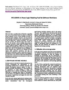
model automatically means that declarations U (red) and U (blue) are also included. The description above can be summarized as follows. We have a set of predicate symbols {U, P, Q}, each assigned with its arity set α (..): α (U ) = {1}, α (P ) = {1, 2}, α(Q) = {1, 2, 3}. In addition, we have two predicate dependencies or rules r, r0 : U Q, whose arities are mappings α (r), α (r0 ) : α (U ) → α (Q) between arity α sets: r (1) = 1 and r0α (1) = 2, where we write rα for α (r). Dependencies serve as inference rules for formulas in the following way. Having a formula Q(a, b, c) with variables a, b, c ranging over T = {red, blue, white, black}, we infer from it formulas U (a) and U (b) by applying dependencies r, r0 , in fact, their arity mappings rα , r0α . We will write r : U (a) Q(a, b, c), r0 : U (b) Q(a, b, c). Thus, our logic for “painting objects” is based on the category Set of sets in the following sense. A signature is a graph (category) Π of predicate and dependency symbols, endowed with an arity graph mapping (functor) α : Π → Set. Simultaneously, our models were sets of types, and instances are sets of objects together with typing as set mappings. 3.1.2 Sketch logic over Graph: Real estate via sketches We continue our discussion of the upper example in Fig. 1. Semantics of the class part of the diagrams is specified by the sketch shown in the right column of Fig. 2: the cell (a) presents the signature (discussed above) and the cell (b) shows the sketch itself. The latter is a graph containing also three labeled diagrams: [key](Oship, property, owner), [cover](property) and [s-valued](date).
(1)
We consider them as predicate declarations or formulas, whose round-bracketed parts actually encode the following mappings: d1 : α [key] → G with d1 (01) = property, d1 (02) = owner 7 ; d2 : α [cover] → G with d2 (12) = property and d3 : α [s-valued] → G with d3 (12) = date, where α denotes the arity assignment and G denotes the carrier graph of the diagram (b) (that is, diagram (b) without labels). In addition, other four labeled diagrams are implicitly assumed in the sketch: they can be inferred by applying dependencies from the signature. For example, the sketch contains also the diagrams [s-valued](property) and [total](property). An instance of the sketch is a graph O of objects and links typed by elements of the sketch so that the incidence between nodes and edges is preserved. A few samples of such typed graphs are presented in Fig. 2(c1,c2). Their elements are pairs (e : t) with e denoting an element of O and t denoting its type (shown in violet with color display). In this way a typing mapping τ : O → G is defined, and it is easy to verify that it is a graph morphism. In addition, this graph morphism must satisfy diagram predicates attached to G (and making it a sketch): τ |= P (d) for all diagrams P (d) in the sketch. Roughly, it means the following. Semantics of the label [cover] with arity α [cover] = 1
→2
is a set of instances ω : Ω → 1 → 2
7
such that
Arrows in the arity graphs are named by the respective pairs of nodes, for example, 01 and 02. Note that the string-based notation used above in declaration (1) is ambigious and does not say whether d1 (01) = property or d1 (01) = owner but in this case it does not matter: the predicate [key] is symmetric
10
Diskin and Wolter Marble Villa :House
Hill House :House
p22 :property
p12:property O1:Oship
O2:Oship
d1:date
01/01/65 :Date
q22 :owner John:Person
Arity shape
s-valued, total, cover
O3:Oship
d2:date
01/01/45 :Date q11 :owner
Predicate symbol
p32 :property
key
q32 :owner
1
Mary:Person
Predicate dependency (c1) A valid instance of schema S Marble Villa :House
Hill House :House
p12:property O1:Oship
p22 :property
O3:Oship
01/01/65 :Date
q22 :owner
q32 :owner
John:Person
0 [s-val,tot]
2 [s-val,tot]
Arity mapping
rsk1 : s-val ⎯| key
rsk1(12) = 01
rsk2 : s-val ⎯| key
rsk2(12) = 02
rtk1 : tot ⎯| key
rtk1(12) = 01
rtk2 : tot ⎯| key
rtk2(12) = 02
d3:date
d2:date
01/01/45 :Date q11 :owner
p31 :property
O2:Oship
d1:date
p32 :property
2
1
(a) Signature, Π
01/01/55 :Date
Mary:Person
House Marble Villa :House
Hill House :House
p12:property O1:Oship
p22 :property
O(wner)ship O3:Oship
q22 :owner John:Person
[s-val]
01/01/65 :Date q32 :owner
[cov] [key] owner
date
d2:date
01/01/45 :Date q11 :owner
p31 :property
O2:Oship
d1:date
property
[Date]
Person
Mary:Person
(c2) Two invalid instances of schema S
(b) Schema/ specification/model/sketch, S
Fig. 2. Object instances as typed graphs
ω −1 (12) : ω −1 (1) → ω −1 (2) is a covering relation (surjection). Semantics of the la-
1
→
←
0 bel [key] is a set of instances ω : Ω →
such that (i) relations ω −1 (01) 2
and ω −1 (02) are totally defined and single-valued, and (ii) the pair of mappings hω −1 (01), ω −1 (02)i is a key. With this semantics of predicate labels, Fig. 2 presents a valid (c1) and two invalid (c2) instances of the sketch in Fig. 2(b). 8 3.1.3 Discussion: From models to sketches We have considered examples of diagrammatic logical specifications over categories Set and Graph. Formalization of other diagrammatic notations used in software modeling leads to similar logical specifications based on these or similar graphbased structures. For example, another popular behavioral model, message sequence 8
The lower instance in (c2) is twice invalid: hτ −1 (property), τ −1 (owner)i is not a key.
11
τ −1 (property) is not surjective and the pair
Diskin and Wolter
charts (MSCs) or close to them UML sequence diagrams can be formally seen as mappings between graphs or 2-graphs (having arrows between arrows), see [11] for details. To manage this variety in a uniform way, we need a generic specification logic, whose syntactical apparatus is based on an arbitrary category Base from a wide class encompassing all interesting cases. For example, a good candidate for this class could be to consider Base to be an arbitrary presheaf topos. We will call such a generic logic a diagram predicate logic and its specifications/theories generalized (Base-)sketches. A remarkable feature of the sketch in Fig. 1(c1) is its visual similarity to the original ER-diagram. We can even consider this diagram as nothing but a specific visual representation of the sketch, in which the diamond node in ER is just syntactic sugar for declaring the [key] predicate and in which the [cover] predicate for arrow property is visualized (in a somehow misleading way) by double framing the target of the arrow. In the same way, the sketch in Fig. 1(c2) makes just explicit that the UML class diagram in (a2) declares actually two opposite multi-valued mappings representing the same binary relation. In this way the generalized sketches treatment (sketching the diagrams) offers both (i) a precise formalization of their semantics and (ii) a framework that is visually appealing and transparent; as our experience shows, it can be readily understood by a software engineer. This is also true for the sketch formalization of UML sequence diagrams [11], and to a lesser extent for sketching UML activity diagrams (a related discussion can be also found in [9]). These considerations and our practical experiments with sketching diagrammatic notations in [12,8,11] give rise to an ambitious thesis: a majority of diagrammatic notations really used in software engineering can be naturally seen as specific visualizations of the universal sketch specification pattern. 3.2
From systems of models to institutions built from sketches
Software development process normally results in a complex system of heterogenous models/specifications. Given a particular modeling language L, e.g., that of ERdiagrams, or relational database schemas, or a sublanguage X of UML, we form the corresponding signature of diagram predicates Π L like it was shown above for ERdiagrams. Thus, we have signatures Π ER , Π Rel , Π U M L[X] and so on. Then L-models can be formalized as Π L -sketches, and their mappings as Π L -sketch morphisms (defined below in Def. 4.6). Systems of similar models form so called horizontal sections of the entire model system. Various sorts of model translation, for example, generating logical relational schemas from ER-diagrams and physical schemas from logical ones, or Java code from high- through middle- and low-level UML-diagrams diagrams form the vertical dimension. In the sketch framework, it is formalized by mappings between sketches in different signatures. Clearly, design of these syntactical mappings and transformation should be based on their semantics. 9 Thus, we need to relate model mappings and transformations with models’ instances and arrange it in a coherent mathematical framework. A standard pattern for such 9
Unfortunately, in the current state of the art of software development, models’ semantics is implicit, which makes model management a very error-prone procedure [3]. It is one of our goals to build a sketch-based semantics for model management [13].
12
Diskin and Wolter
an arrangement is the notion of institution [17]. However, its application to the DP-logic, that is, relating institution’s ingredients to DP-logic ingredients, is not straitforward. In the context of the present informal discussion, it is convenient to call and denote the institution ingredients in the following way. What is usually called signatures, we will call structure specifications, or i-signatures to distinguish them from diagrammatic predicate signatures considered above. Correspondingly, i-sentences are called constraints and i-models are called instances. Thus, an institution is a quadruple I = (Str, ctr ctr, inst inst, |=) with Str a category of structure specifications, ctr : Str → Set and inst : Strop → Cat are functors and |= a family of binary satisfaction relations (|=S : S ∈ Str) satisfying the translation axiom as usual. A specification/theory/model is a pair S = (S, C) with S ∈ Str the structural part (an i-signature) and C ⊂ ctr ctr(S) a set of constraints (i-sentences). In applications we discussed above, the structural part of models is given by graphs, Str = Graph or, in general, some category Base of graph-like objects (we may thank of Base as a presheaf topos). Constraints are diagrams labeled by predicate symbols from a predefined signature Π L . Choosing a semantics interpretation for predicate symbols (see Def. 4.7 below) provides instances (Def. 4.12), which should complete this structure to an institution-like formalism (we will show it in the next section). Thus, an interpreted predicate signature determines an institution. 10 Correspondingly, sortwise signature morphisms are better to be considered together with their intended semantics interpretations and hence as institution morphisms. In this way, homogeneous (horizontal) model systems are arranged as institutions – each one generated by its own interpreted predicate signature Π , while vertical model transformations are based on morphisms of Π -signatures formalized as institutions morphisms. In the present paper we deal only with horizontal model mappings and do not consider (vertical) signature morphisms. One reason is space limitations. Another reason is that it is appropriate to treat signature morphisms within a more advanced categorical presentation of the DP-logic than we are going to develop in the paper. We will address this in a forthcoming paper. Thus, in the next section we will build an institution for the DP-logic over fixed interpreted predicate signature Π and with Base-objects in the role of i-signatures, Str=Base. It can be done in a rather straitforward way similar to any other institution built for a functorial semantics logic, where the reduction, or forgetful, functors are simply defined by pre-composition. The only point that needs caution is that for our fibred semantics forgetful functors are defined by pullbacks rather than composition. Since pullbacks are determined only up to isomorphism, for the fibred semantics the i-model functor is lax, i.e., is a pseudo-functor.
10 We
call a signature interpreted if it has some fixed predefined semantics Def.4.7. Note that considering predicate signatures appearing in practice as interpreted is quite natural. For example, the predicate symbol [key] is like a predicate constant of arity “span” with predefined semantics of being jointly-monic.
13
Diskin and Wolter
4
Generalized sketches as a logical machinery
4.1
Syntax
This subsection presents the syntactic side of the DP-logic. The terminology is motivated mainly by the case of the base category being Graph, the category of directed (multi)graphs. However, to show parallels with ordinary string-based logics, we sometimes introduce two names for the same notion: graph-based and stringbased logic motivated. Table 1 makes these parallels explicit. The reader is advised to consult with this Table while reading definitions below. Let Base be some base category, arbitrary but fixed throughout the rest of the paper. Definition 4.1 (Signatures) A signature over Base is given by a category Π of predicate and dependency symbols and a functor α : Π → Base. For an object P ∈ Π , the Base-object α (P ) is called the arity (shape) of P , and for a dependency arrow r : Q P in Π , α (r) : α (Q) → α (P ) is called an arity substitution. We will often write αP for α (P ) and rα for α (r). We shall never deal with the situation of a few arity mappings defined on the same Π , neither we will deal with signature morphisms in this paper. Hence, we can safely follow the terminological tradition of ordinary FOL and refer to a signature by the domain of the arity mapping. Formulas in our generic logic are defined for a fixed context that is chosen independently of a given signature. Definition 4.2 (Formulas and derivations) Let G be an object in Base to be thought of as the structural base/carrier graph of the specification. (i) A labeled diagram or a formula over G is a pair φ = (P, d) with P a predicate symbol and d : αP → G a morphism (usually called a diagram of shape αP in the categorical jargon). Following notational traditions of string-based logics, we will denote formulas by expressions P (d), and write G P (d) if we want to make the context/carrier object explicit. Let Π,G) = {P (d) | P ∈ Π , d ∈ Base(αP, G) } Fm(Π denote the set of all Π-labeled diagrams/formulas over G. P a predi(ii) A derivation over G is a triple hr, Q(rα ; d), P (d)i with r : Q cate dependency in Π , and P (d) a formula over G. We will write such a derivation as a labeled sequent, r : Q(rα ; d) P (d) and say that it is produced by applying the dependency/rule r : Q P to P (d). In this way, predicate dependencies serve as inference rules. In general, the same formula Q(rα ; d) can be derived with another dependency 0 r :Q P if rα ; d = r0 α ; d. Identical dependencies provide identical sequents α since (idQ ) = idαQ for all predicate symbols Q. Moreover, we have q α ; pα = (q; p)α for all composable dependencies q : Q R, p : R P , and the associativity of composition in Base ensures that labeled sequents q : Q(q α ; (pα ; d)) R(pα ; d) and p : R(pα ; d) P (d) compose to a labeled sequent q; p : Q((q; p)α ; d)) P (d). In such a way, the set of formulas together with the set of labeled sequents defines 14
Diskin and Wolter
Π, G) (note the bold font). a category Fm Fm(Π As most of specification formalisms, DP-logic offers translations of formulas caused by variable substitution. Let s : G → G0 be a morphism in Base, which we may think of as a substitution of names/variables. The translation of formulas def is based on the functor s∗ : Base ↓ G → Base ↓ G0 defined by s∗ (A, d) = (A, d; s) def
for all objects (A, d : A → G) in Base ↓ G and by s∗ (f ) = f for all morphisms f : (A, d) → (B, e) in Base ↓ G. 11 Construction 4.3 (Formula substitutions) Given s : G → G0 and formula ϕ = def P (d), we define s∗ (ϕ) = P (ss∗ (d)) = P (d; s). Substitution preserves derivations in the following sense. Given a derivation G Q(rα ; d)
r
P (d),
we translate P (d) to s∗ (P (d)) = P (d; s) and Q(rα ; d) to s∗ (Q(rα ; d)) = Q[(rα ; d); s]. By associativity of composition in Base, the latter formula can be rewritten as Q[rα ; (d; s)] and hence we have a derivation G0 s∗ (Q(rα ; d))
r
s∗ (P (d)).
It is easy to check that in this way a substitution s : G → G0 gives rise to a Π, G) → Fm Π, G0 ) between formula categories. functor Fm Fm(s) : Fm Fm(Π Fm(Π Π, G) and s 7→ Corollary 4.4 (Formula functor) The assignments G 7→ Fm Fm(Π Fm Fm(s) define a formula functor Fm Π : Base → Cat. We call specifications or theories in DP-logic sketches. Definition 4.5 (Sketches) A sketch over a signature Π is a pair G = (G, T ) Π, G) a set of diawith G the carrier graph (an object in Base) and T ⊂ Fm(Π P in Π the following grams/formulas over G. In addition, for any arrow r : Q inference condition must hold: (Inf)
if formula P (d) ∈ T then Q(rα ; d) ∈ T as well.
In other words, the formula set T is closed under inference rules recorded in the signature and can be called a Π -theory (hence, the letter T ). Π, G), we come By taking the full category generated by T in the category Fm Fm(Π to a theory category T . Thus, a sketch can be considered as a pair G = (G, T ) with Π, G) closed under all derivations (and hence being a full T a subcategory of Fm Fm(Π subcategory). The usual requirement for a morphism between theories that the target theory has to entail the translated source theory is reflected in the sketch formalism by the existence of functors. 11 We
remind that slice category Base ↓ G has pairs (A, d) with d : A → G as objects, and arrows f : A → B in Base such that f ; e = d as morphisms.
15
Diskin and Wolter
O∗ τ∗
↓ αQ
rα∗ →O τ ↓ → αP α
[PB]
r semantics of de(a) pendencies
O∗∗ τ ∗∗
↓ αQ
rα∗ d∗ → O∗ →O τ ∗[PB] τ ↓ ↓ →G → αP d rα
[PB]
(b) satisfaction relation
O∗∗ τ ∗∗
↓ αP
d0∗ s∗ → O∗ →O τ ∗[PB] τ ↓ ↓ 0 →G →G s d0
[PB]
(c) sketch morphisms
Fig. 3. Semantic notions
Definition 4.6 (Sketch morphisms) A morphism s : G → G 0 between sketches G = (G, T ) and G 0 = (G0 , T 0 ) is a substitution s : G → G0 such that the translation of Π, G) → Fm Π, G0 ) restricts to a functor hhssii : T → T 0 . formulas Fm Fm(s) : Fm Fm(Π Fm(Π The category of sketches and their morphisms over a fixed signature Π will be Π). denoted by Ske(Π 4.2
Semantics of a sketch
Consider an object G ∈ Base as a model (in the engineering sense). Then, in the fibred (IATS) view of semantics, any morphism τ : O → G is an instance of/over G, thus the category of all instances over G is given by the slice category Base ↓ G. We will denote isomorphisms in this category by ∼ =. An object G is a purely structural model without any constraints. In the sketch framework, the latter are diagrams in G, and we need to define the notion of satisfiability of diagrams by instances. We do this below via the operation of pullback, and hence we assume that Base has pullbacks. In more detail, for every arrow cospan (x, y) in Base, we choose a fixed pullback span (x∗ , y ∗ ) = P B(x, y) with the following notational agreement. If x∗ , y ∗ are “parallel” to x, y respectively, we write def def x∗ = P By (x) and y ∗ = P Bx (y). Then the familiar lemma that composition of i
pullbacks is again a pullback takes the following form: P Bx1 ;x2 (y) ∼ = P Bx1 [P Bx2 (y)] with i = i(x1 , x2 , y) a canonical isomorphism satisfying the corresponding coherence conditions. Clearly, before defining the next ingredient for an institution, namely, the satisfaction relation between G-instances and diagrams over G, we have to fix a semantic interpretation for the predicate symbols in our signature. Definition 4.7 (Semantics of Signatures) Given a signature α : Π → Base, its semantic interpretation is a mapping [[ .. ]], which assigns to each predicate symbol P a set [[ P ]] ⊂ {τ ∈ Base | cod τ = αP } of valid instances, where [[ P ]] is assumed to be closed under isomorphisms: τ ∈ [[ P ]] implies i; τ ∈ [[ P ]] for any isomorphism i : O0 → O in Base. The semantic interpretation is consistent if for any dependency r: Q P in Π and any valid instance τ : O → αP of P , the induced instance def ∗ τ = P Brα (τ ) is a valid instance of Q (Fig. 3a). Below we will assume consistency by default (see Remark 4.11).
16
Diskin and Wolter
Example 4.8 Consider the signature specified in Fig. 2. For a graph mapping τ : O → G, we form another graph mapping τ −1 : G → Rel into the category of sets and binary relations. For the predicates P = [s-val], [tot], [cov], τ ∈ [[ P ]] iff, respectively, τ −1 (12) is a single-valued, totally defined, covering relation, where 12 is the only arrow of the arity graph of these predicates. For the predicate P = [key], τ ∈ [[ P ]] iff (a) the legs of the span (τ −1 (01), τ −1 (02)) are totally defined singlevalued mappings and (b) the span is jointly monic (i.e., is a key to the set τ −1 (0)). Condition (a) ensures consistency. Now we define satisfiability of formulas in semantic instances. Definition 4.9 (Satisfaction relation) Let G be an object in Base and τ : O → G its instance. We say that this instance satisfies a labeled diagram/formula P (d) over def
G and write τ |=G P (d), iff τ ∗ = P Bd (τ ) ∈ [[ P ]] (see Fig. 3b). In other words, an instance of some model satisfies a labeled diagram/formula over this model if the part of this instance over the diagram is a valid instance of its label. The consistency assumption ensures soundness w.r.t. derivations. Proposition 4.10 (Soundness) If τ |=G P (d) and r : Q(rα ; d) derivation, then τ |=G Q(rα ; d).
P (d) is a
Proof. τ |=G P (d) iff τ ∗ = P Bd (τ ) ∈ [[ P ]] and this implies τ ∗∗ = P Brα (τ ∗ ) ∈ [[ Q ]] due to consistency (see Fig. 3b). Morphisms τ ∗∗ and P Brα ;d (τ ) are isomorphic in Base ↓ G since the composition of two pullbacks is again a pullback. By assumption, [[ Q ]] is closed under isomorphisms, and thus we obtain P Brα ;d (τ ) ∈ [[ Q ]], i.e., τ |=G Q(rα ; d). 2 Remark 4.11 (Consistency) Following the tradition of functorial semantics, the original definitions of semantics for generalized sketches have been based on indexed concepts. The obvious idea is to transform a chosen semantic universe U given by a category like Set, Par, Graph or Cat into a “semantic Π -sketch” U = (U, U ) by defining for each predicate symbol P in Π its semantic meaning, that is, the set of “all valid diagrams” d : αP → U ). A model (in the logical sense, i.e., i-model in terms of section 3.2) of a Π -sketch G is then given by a sketch morphism from G into U (see [6,7,27,28]). Such an indexed semantics can be transformed into a fibred semantics, as presented here, if the underlying category allows for a variant of the so-called Grothendieck construction [18]. 12 . The Grothendieck construction turns composition into pullbacks, and Proposition 4.10 makes apparent that the consistency condition in Def. 4.7 is just the “fibred counterpart” of the requirement that U = (U, U ) has to be a Π -sketch, i.e., that U has to be closed under inference rules recorded in the signature (compare Def. 4.5). In other words, any indexed semantics, where the underlying category allows for a variant of the Grothendieck construction, provides a consistent fibred semantics for predicate signature in the sense of Def. 4.7. Definition 4.12 (Instances of a sketch) Let G = (G, T ) be a sketch. Its instance is an instance τ : O → G of the structural base, such that all formulas of the 12 In
[27], we have analysed, the variant for the category Graph.
17
Diskin and Wolter
sketch are satisfied: τ |= P (d) for all P (d) ∈ T . It gives us the set of all instances Inst(G) of sketch G. Let Inst(G) denote the full subcategory of category Inst(G) = Base ↓ G generated by the set Inst(G) of all instances of sketch G. 4.3
Semantics of a system of sketches: An institution arrangement
We have already built the syntactical part of the institution with Corollary 4.4 (take formulas/diagrams as i-sentences). As for semantics, we begin with the following old result [15, p.16]. Lemma 4.13 (Forgetful Functor) Any morphism s : G0 → G in Base induces a functor s∗ : Base ↓ G → Base ↓ G0 right-adjoint to the functor s∗ : Base ↓ G0 → Base ↓ G, def s∗ a s∗ , where s∗ (τ ) = P Bs (τ ) for any instance τ : O → G of G (see Fig. 3(c)). Since pullbacks are only determined up to isomorphism, we cannot obtain that for any morphisms s0 : G00 → G0 , s : G0 → G, the functors (s0 ; s)∗ and s∗ ; s0∗ are equal. We can, however, prove that the functors (s0 ; s)∗ and s∗ ; s0∗ are naturally isomorphic. Moreover, we can prove that the family of those natural isomorphisms satisfies the corresponding coherence conditions that give rise to Proposition 4.14 (Instance functor) The assignments G 7→ Base ↓ G and s 7→ s∗ define an instance pseudo functor Inst : Baseop → Cat. The last ingredient of an institution, the so-called satisfaction condition, is ensured for the fibred semantics by the fact that pullbacks are closed under composition and decomposition, respectively. Corollary 4.15 (Satisfaction Condition) For any morphism s : G0 → G in Base, any instance τ : O → G of the structural base G, and any formula P (d0 ) over the structural base G0 we have τ ∗ |=G0 P (d0 )
iff
τ |=G P (d0 ; s).
Proof. (⇒) τ ∗ |= P (d0 ) means, due to Definition 4.9 and Lemma 4.13, that τ ∗∗ = P Bd0 (τ ∗ ) = P Bd0 (P Bs (τ )) ∈ [[ P ]] (see Fig. 3(c)). The composition of two pullbacks is again a pullback thus P Bd0 ;s (τ ) and τ ∗∗ are isomorphic. This means that P Bd0 ;s (τ ) ∈ [[ P ]] since [[ P ]] is closed under isomorphisms, and thus τ |=G P (d0 ; s) due to Definition 4.9. (⇐) τ |=G P (d0 ; s) means that P Bd0 ;s (τ ) ∈ [[ P ]]. We know, however, that the pullback P Bd0 ;s (τ ) can be factored through the pullback τ ∗ = P Bs (τ ), meaning that we have an isomorphims between P Bd0 (τ ∗ ) = P Bd0 (P Bs (τ )) and P Bd0 ;s (τ ). This entails P Bd0 (τ ∗ ) ∈ [[ P ]], since [[ P ]] is closed under isomorphisms, and thus τ ∗ |= P (d0 ). 2 Summarizing the development so far, we can formulate Theorem 4.16 ((Pseudo) Institution) Let Base be a category with an operation of pullback, and α : Π → Base be a signature over Base. Then the formula functor Fm Π : Base → Graph, the instance pseudo functor Inst : Baseop → Cat 18
Diskin and Wolter
and the family (|=G | G ∈ Base) of satisfaction relations constitute a pseudo institution. One of the insights of the theory of institutions is that the satisfaction condition allows to extend i-model functors to “generalized i-model functors” for theories. For the DP-logic, the standard argumentation instantiates as follows. Corollary 4.17 If s : G 0 → G is a sketch morphism and τ : O → G is an instance of G, then s∗ (τ : O → G) = τ ∗ : O∗ → G0 is an instance of G 0 (see Fig. 3(c)). Proof. For any formula P (d0 ) in T 0 we have τ |=G0 P (d0 ; s) = hhssii(P (d0 )) since s is a sketch morphism and (O, τ ) is an instance of G. This, however, implies τ ∗ |=G0 P (d0 ) due to (one direction of) the satisfaction condition. 2 Since Inst(G 0 ) and Inst(G) are full subcategories of Base ↓ G0 and Base ↓ G, respectively, Corollary 4.17 ensures that the forgetful functor restricts to instances. Proposition 4.18 (Forgetful functor for sketches) For any sketch morphism s : G 0 → G, the forgetful functor s∗ : Base ↓ G → Base ↓ G0 restricts to a functor [[ s ]] : Inst(G) → Inst(G 0 ). Finally, we can summarize Propositions 4.18 and 4.14 with our second main result. Theorem 4.19 (Generalized instance functor) For any base category Base with pullbacks and any signature α : Π → Base over Base, the assignments G 7→ Inst(G) Π)op → Cat. and (s : G 0 → G) 7→ [[ s ]] define a pseudo functor Inst : Ske(Π
5
Historical remarks, relation to other and future work
5.1
Historical remarks.
Applications of categorical logic to data modeling were first described, probably, in [5], with a major emphasis on commutative diagrams and less on the universal properties. In the same context of data modeling, the machinery of generalized sketches was developed and applied in a few industrial projects in Latvia in 199394 [4], and the corresponding logic presented at Logic Colloquium’95 [7]. Even earlier, Michael Makkai came to the need to generalize the notion of Ehresmann’s sketches from his work on an abstract formulation of Completeness Theorems in logic. Makkai attributed the immediate impetus for him to work out these ideas to Charles Well’s talk at the Montreal Category Theory Meeting in 1992. Well’s own work went in a somewhat different direction [1] while Makkai’s work resulted in the notion (and the very term) of generalized sketch. Makkai also developed a corresponding mathematical theory that was first presented in his several preprints circulated in 1993-94, and summarized and published later in [21]. Relations between generalized sketches as they are understood by Makkai and other generalization of the Ehresmann’s concept are discussed in the introduction to [21]. The “Latvian” version of the definition of ordinary sketches coincides with Makkai’s definition (but emphasizes the parallelism between sketches and sets of 19
Diskin and Wolter
atomic formulas in FOL). In addition, the Latvian version defines sketches over signatures with operation symbols [6], which we do not consider in this paper. The original definitions of sketch semantics [7,6,21] are based on the “indexed view” in the sense that semantics of sketches is given by morphisms from specifications into a semantic universe. And as far as we know, semantic notions based on the “fibrational view”, i.e., the Instances-as-typed-structures idea, are developed first in the present paper. An ongoing research project at University of Bergen and Bergen University College aiming at practical applications of generalized sketches made apparent instantly the need for dependencies. The corresponding formal concepts and results have been presented first at LSFA’06 (see [28]). 5.2
Future work
We see the present paper as a common root of two lines (in fact, trees) of future work. One is to adopt the sketch formalism for formalizing modeling languages actively used in software engineering practice and specified in the corresponding industrial standards. Especially intriguing is to try to adapt the sketch patterns for behavior modeling. We also plan to explore how naturally can sketches be used for addressing real practical problems. On the other hand, the formalism poses many interesting and non-trivial mathematical problems. (a) Makkai has introduced “multisketches” in [21] and he has shown that the category of multisketches is isomorphic to a certain presheaf topos in all cases, where the base category is a presheaf topos itself (for example, the category Graph). This result is important for applications and implementations of sketches, and we are going to extend Makkai’s constructions and results to signatures with dependencies. (b) A fully fledged sketch logic going beyond dependencies is still to be developed. (c) “Sketch operations” are the key to formalize model transformations and other aspects in Model Driven Development. A full exposition of these operations has to be given where especially the relation to Graph Transformations and to the concept of axioms in [21] will be of interest. (d) Finally, there are different ways to reformulate the definitions and results in this paper in a more categorical way. An investigation in this direction seems to be not only of theoretical interest.
References [1] A. Bagchi and C. Wells. Graph-based logic and sketches. In 10th Int.Congress of Logic,Methodology and Philosophy of Science, Florence, 1995, Florence (Italy), 1997. Kluwer Acad.Publ. [2] M. Barr and C. Wells. Category Theory for Computing Science. Prentice Hall International Series in Computer Science, 1995. [3] P. Bernstein, A. Halevy, and R. Pottinger. A vision for management of complex models. SIGMOD Record, 29(4):55–63, 2000. [4] B. Cadish and Z. Diskin. Algebraic graph-oriented approach to view integration. Part I: Specification framework and general strategy. Technical Report 9301, Frame Inform Systems/LDBD, Riga, Latvia, 1993. http://citeseer.ist.psu.edu/340019.html. [5] C.N.G. Dampney, M. Johnson, and G.P. Monro. An illustrated mathematical foundation for ERA. In C.M. Rattray and R.G. Clarke, editors, The Unified Computation Laboratory. Oxford University Press, 1992.
20
Diskin and Wolter [6] Z. Diskin. Databases as diagram algebras: Specifying queries and views via the graph-based logic of skethes. Technical Report 9602, Frame Inform Systems/LDBD, Riga, Latvia, 1996. http://citeseer.ist.psu.edu/116057.html. [7] Z. Diskin. Towards algebraic graph-based model theory for computer science. Bulletin of Symbolic Logic, 3:144–145, 1997. Presented (by title) at Logic Colloquium’95. [8] Z. Diskin. Visualization vs. specification in diagrammatic notations: A case study with the UML. In Diagrams’2002: 2nd Int. Conf. on the Theory and Applications of Diagrams, Springer LNAI#2317, pages 112–115, 2002. [9] Z. Diskin. Mathematics of UML: Making the Odysseys of UML less dramatic. In Ken Baclawski and Haim Kilov, editors, Practical foundations of business system specifications, pages 145–178. Kluwer Academic Publishers, 2003. [10] Z. Diskin. Mathematics of generic specifications for model management. In Rivero, Doorn, and Ferraggine, editors, Encyclopedia of Database Technologies and Applications, pages 351–366. Idea Group, 2005. [11] Z. Diskin, J. Dingel, and H. Liang. Scenario integration via higher-order graphs. Technical Report 2006-517, School of Computing, Queen’s University, Kingston, ON, Canada, 2006. http://www.cs.queensu.ca/TechReports/reports2006.html. [12] Z. Diskin and B. Kadish. Variable set semantics for keyed generalized sketches: Formal semantics for object identity and abstract syntax for conceptual modeling. Data & Knowledge Engineering, 47:1–59, 2003. [13] Z. Diskin and B. Kadish. Generic model management. In Rivero, Doorn, and Ferraggine, editors, Encyclopedia of Database Technologies and Applications, pages 258–265. Idea Group, 2005. [14] H. Ehrig and M. Große-Rhode. Functorial Theory of Parameterized Specifications in a General Specification Framework. Theoretical Computer Science, (135):221 – 266, 1994. [15] P. Freyd. Aspects of topoi. Bull. Austr. Math. Soc., (7):1–72, 1972. [16] P. Freyd and A. Scedrov. Categories, Allegories. Elsevier Sciece Publishers, 1990. [17] J. A. Goguen and R. M. Burstall. Institutions: Abstract Model Theory for Specification and Programming. Journals of the ACM, 39(1):95–146, January 1992. [18] B. Jacobs. Categorical logic and type theory. Elsevier Science Publishers, 1999. [19] M. Johnson, R. Rosebrugh, and R. Wood. Entity-relationship-attribute designs and sketches. Theory and Applications of Categories, 10(3):94–112, 2002. [20] J. Lambek and P. Scott. Introduction to higher order categorical logic. Cambridge University Press, 1986. [21] M. Makkai. Generalized sketches as a framework for completeness theorems. Journal of Pure and Applied Algebra, 115:49–79, 179–212, 214–274, 1997. [22] F. Piessens and E. Steegmans. Proving semantical equivalence of data specifications. J. Pure and Applied Algebra, (116):291–322, 1997. [23] J. Rumbaugh, I. Jacobson, and G. Booch. The Unified Modeling Language Reference Manual. Second Edition. Addison-Wesley, 2004. [24] Bran Selic. Model-driven development: Its essence and opportunities. In ISORC, pages 313–319, 2006. [25] D.C. Tsichritzis and F.H. Lochovsky. Data models. Prentice-Hall, Englewood Cliffs, N.Y., 1982. [26] C. Wells. Sketches: Outline with references. Available under http://www.cwru.edu/artsci/math/wells/ pub/papers.html. [27] U. Wolter and Z. Diskin. From Indexed to Fibred Semantics – The Generalized Sketch File. Technical Report Report No 361, Department of Informatics, University of Bergen, October 2007. [28] U. Wolter and Z. Diskin. The Next Hundred Diagrammatic Specification Techniques – An Introduction to Generalized Sketches. Technical Report Report No 358, Department of Informatics, University of Bergen, July 2007.
21