Submitted to Workshop on Communication Architecture for Clusters – CAC’02
A Fairness Algorithm for High-speed Networks based on a Resilient Packet Ring Architecture Stein Gjessing Simula Research Laboratory University of Oslo, Pob. 1080 Blindern, Oslo, Norway Email:
[email protected] Abstract IEEE is currently standardizing a spatial reuse ring topology network called the Resilient Packet Ring (RPR, IEEE P802.17). The goal of the RPR development is to make a LAN/MAN standard, but also WANs are discussed. A ring network needs a fairness algorithm that controls each stations access to the ring. The RPR fairness algorithm is currently being developed with mostly long distances between stations in mind. In this paper we discuss how the algorithm needs to be changed in order to give good performance if and when RPR is used for high-speed networks and LANs with shorter distances between stations. We discuss different architectural parameters including buffers sizes and distance between stations. We suggest the use of triggers instead of timers to meet the tighter latency requirements of highspeed networks. The proposed improvements are compared and evaluated using a ring network simulator that we have built in the Java programming language. Keywords: Resilient Packet Ring, High-speed networks, Network interface, Fairness algorithm, Packet latency 1. Introduction IEEE is currently undertaking a standardization effort called the Resilient Packet Ring, RPR. The RPR standardization group works under the LAN/MAN umbrella, and is designated IEEE P802.17. The goal of the group is to define a standard that can be used for high-speed LANs and MANs, but the companies that are most active in the standardization work also sees it as a WAN technology. Another goal is to be able to use physical layers of different kinds, e.g. high-speed point-to-point Ethernet. RPR will define a full duplex ring topology. The nodes on the ring are called stations. A subnet that connects all the stations and moves traffic in one direction around the ring is called a ringlet. RPR will spatially reuse the ring bandwidth by letting the destinations strip the packets. Hence one packet may flow on one segment of a ringlet while another packet flows on another part of the same ringlet at the same time. Figure 1 shows a ring with 16 stations where spatial reuse is illustrated on the inner ringlet. Notice that each station is connected to two ringlets, and has a full duplex connection to the outside. Figure 2 shows one ringlet interface with ingress, egress and passthru buffers. Packets on their way into the ring are stored in the ingress buffer, while packets that are stripped from the ring are stored in the egress buffer. Packets that are traveling by a station on the ring, while this station sends out a packet from its ingress buffer, will have to wait in the stations passthru buffer. The advantage of a ring topology is that it is built from several very fast point-to-point connections. Each station is simpler than a switch. It is possible to design the ring interface so that packets moving around the ring are never thrown away due to congestion. Ring networks have been designed and built for a long time, and are also extensively studied in the literature. One of the first ring network topologies was the Cambridge ring [18] that was designed in the 1970’s. Two important ring topology standards, the IEEE Token Ring [10] and the FDDI [21] were
1
developed later. The first ring networks used a token to regulate the access to the communication medium. Later destination stripping with spatial reuse was exploited in systems like MetaRing[6], DQDB [11], ATMR [13], CRMA-II [15] and SCI [12]. Access to the ring must be controlled by a fairness or flow control algorithm, and several have been proposed and evaluated [2,5,9,16,17,20].
0
1
2
3
4
5
6
7
15
14
13
12
11
10
9
8
Figure 1. A ring built from two ringlets with spatial reuse shown on the inner ringlet where station 5 sends to station 0 at the same time as station 13 sends to station 9. Cisco has developed a ring network called Dynamic Packet Transport with a fairness algorithm called the Spatial Reuse Protocol (SRP) that is described in an Internet Engineering Task Force “Request for Comments” document [23]. SRP uses low pass filters to smooth the traffic, and we do the same in our implementation of a ring access fairness algorithm [24] that we propose for the RPR standard. The rest of this paper is organized as follows: In the next section we discuss some factors that could make RPR more suitable for high-speed networks and LANs. We also outline a new version of our fairness algorithm that we believe is better for high-speed networks. Then in section 4 we describe our experimental platform, and in section 5 we present the initial experiment we have conducted to test our ideas. In section 6 we conclude and point out further work. 2. Problem statement A naïve algorithm for access to the ring is that a station is allowed to send whenever the passthru buffer is empty, or at least almost empty. However, a station that is sending a lot can effectively starve a downstream station if this simple access principle is used. In order to avoid such unfair behavior by some stations, a more complex fairness algorithm is needed. RPR will support at least two priority levels with two sets of passthru and two sets of ingress buffers. The goal is that high priority packets have absolute priority over low priority traffic. The high priority traffic is assumed to be provisioned and far below the total available bandwidth. Hence the fairness algorithm does not need to control high priority traffic. Except for the congestion notification packets that are explained below, we use low priority packets only, in the work reported in this article. For low priority packets the base rule of our fairness algorithm [24] is that packets in the passthru and the ingress buffers have equal priority. Hence the station chooses a packet from each queue every second time (or really keeps a byte count in case the packets vary much in size). When the station sends out its own packets, at the same time as packets arrive on the ring, the passthru buffer is filling up. In order for the buffer not to overflow, when its size is above a certain threshold, the station itself is not allowed to send packets; all packets sent are from the passthru buffer. When the station is in this situation we say that it is congested. It must then send a congestion notification packet upstream (on the link going in the other direction) and ask the stations there to send less. In the SRP algorithm [23] the congestion notification packet contains the congested stations own send rate. We use the same principle in our algorithm. The station immediate upstream from a link is called the guard of
2
that link. The idea is that, as a first approximation, when a guard station is congested, no upstream station shall send more than the guard itself is sending across the guards link (or no more than a weighted part of this). When the upstream stations react to the congestion notification packet and send less, the guards passthru buffer is emptied below the threshold, and the guard station can start to send again. As long as an upstream station receives congestion notification packets, it adjusts to the sending values in these packets. When a station does not receive any more notifications, it gradually increases its send rate again. In this way all stations get to send the same amount after a while. In a WAN it can take some time for the stations to converge to the same send value. In a high-speed network convergence should be much faster. In the sequel we discuss this convergence and the latency of packets involved in such congestion. In the SRP algorithm it is suggested to run the congested stations own send rate thru a low pass filter before the value is sent upstream. It is suggested that a current (over the last 100 microseconds) send rate should weight 1/512 of the historic rate. When the upstream station is not receiving any more congestion notification packets, it increases its send rate. The SRP suggests that it should be increased by 1/64 of the difference between the current send value and the maximum allowed value. We call the numbers 512 and 64 aging values. In the sequel these values are discussed in the context of high-speed networks. The two numbers 512 and 64 are called the original aging values.
Egress buffer
Ingress buffer
Passthru buffer
Figure 2 Single ringlet network interface A downstream station broadcasts a congestion notification to all upstream stations when it is congested. From the time the notification is sent, to the station experiences less input into its passthru buffer, at least one roundtrip time to the upstream station will incur. Hence the notification should be sent some time before the passthru buffer is too full, and this time is proportional to the distance to the upstream nodes. Again SRP uses half the threshold size to indicate that congestion might occur, and that a congestion notification packet should be sent. We have adopted the same strategy. Obviously a high-speed network has tighter latency constraints than a MAN or a WAN that has long distances between stations. In the SRP, the stations check their states about every 100 microseconds in order to see if a congestion notification has arrived or should be sent. In this paper we propose that in a high-speed network it is important to discover these two situations as early as possible. We propose the use of triggers so that the correct actions can be taken immediately and we discuss and evaluate how this is improving the behavior of the network. 3. The experimental platform We have developed a model of RPR. This model consists of two counter rotating rings connecting all stations (figure 1). The model is described in the programming language Java. The model is built on top of our Java simulation kernel. Hence we can run the model and see how it behaves under different architectural parameters and different traffic patterns. The model is flexible; we can change it or extend it using the Java language. The RPR standard will probably not be completed until 2003. Hence our model
3
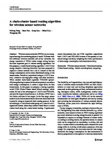
is so far just our own impression of the direction and the status of the working group. It is, however, also a very generic full duplex ring topology model. Hence our results are applicable to any such ring based network that uses destination stripping. In MANs and in WANs the distance between stations are measured in kilometers. In LANs and highspeed networks the distance is measured in meters. The difference in propagation delay and the expected packet latency is a key difference between these kinds of networks. This report focuses on high-speed networks and we will hence use a relatively short distance, mostly about 25 meters, between the stations. In 125 ns link signals travel 25 meters. We assume that it is possible to build ring stations that forwards packets in another 125 ns. This is the time it takes to receive the first few bytes of the header, look at the MAC address and decide if the packet should be stripped or sent on. Hence, in most of our experiments, the latency experienced by a packet going around the ring is 250 ns. per hop. The link speed used is one Gbyte/sec. We use data packets that are low priority and 500 bytes long, while the congestion notification packets are 32 bytes high priority packets. In some of the experiments we vary the passthru buffer size, but the size is mostly 5000 bytes, with a threshold value of 3000 bytes. The Java model is a program of about two thousand lines, hence it contains errors. The main parts of the model have been running since April 2001, and have been tested on a number of different traffic scenarios. It still contains bugs, but we believe that the results presented in this paper are reasonably correct irrespective of the bugs left in the model. 4. The Experiment In order to do the initial testing and evaluations of our hypotheses, including the proposed triggers in the fairness algorithm, we found one experiment that gives a lot of valuable insight. We ran this experiment with different architectural parameters, and for each parameter setting we have executed runs with different seeds. These different runs with different seeds have always shown the same basic behavior as the ones we are using for illustrations in the sequel. The experiment is pictured in figure 3. Station 0 sends at full speed (2 packets per microsecond) to station 6 for the duration of the experiment (22 milliseconds). Station 2 starts a full speed flow to station 4 at time 2 milliseconds, and terminates this flow after 16 milliseconds, i.e. at time 18 milliseconds.
0
1
2
3
4
5
6
Figure 3. A ringlet segment with two competing flows. When station 2 starts to send (after 2 milliseconds), its fairness algorithm for a while takes every second packet from the passthru buffer and the ingress buffer. Both buffers rapidly fills up, and when the passthru buffer reaches half of the threshold, the station prepares to send a congestion notification message upstream (upstream links are not showing in figure 3). In the SRP algorithm, the size of the passthru buffer is checked at regular intervals. In a MAN/WAN network, this can typically be done every 100 microseconds [23]. The plot marked “Timer 100 microsec” in figure 4 shows that in a high-speed network, this is not a good idea. We will first explain the nature of figure 4.
4
We have run the experiment with four different versions of the fairness algorithm (figure 4). The latency that packets experience from the moment they are ready to be put onto the ring by station 2, until they reach station 4, are plotted on the y-axis. Only packets from station 2 to station 4 are represented. Each point in the plot represents one packet. The time the packet is accepted by station 4 is shown on the x-axis. When the passthru buffer in station 2 has reached the threshold value (3000 bytes), only packets from the passthru buffer are forwarded downstream. For each run the top latency value is the latency of the packet sitting at the head of the ingress buffer in station 2 when the passthru buffer reaches the threshold, and station 2 is not allowed to send any more. This packet has to wait for the congestion notification signal to reach station 0, and also wait for station 0 to send less traffic. Then the passthru buffer will shrink below the threshold, and the packet that has waited can finally be transmitted. First packets latency 120 100
Latency in microsec.
80
Timer 100 microsec. Timer 20 microsec Timer 10 microsec Triggered
60 40 20 0 2000
2025
2050
2075
2100
2125
Time in m icrosec.
Figure 4. The latency of the first packets in the new flow from station 2 to station 4 The slower the fairness algorithm reacts to the congestion, and also the slower the upstream station reacts to the received congestion notification packet, the longer the packet at the head of the ingress queue in station 2 has to wait. We have tried with 100 microsecond timers, 20 microsecond timers and 10 microsecond timers. In all these cases we see that the latency is high. The latency will also depend on when the timer hits compared to the state of the stations involved in the congestion. Even though figure 4 is just a plot of one run for each timer setting, we believe it shows a fair comparison between the schemes. The latency values shown for the timers in figure 4 are acceptable for a MAN/WAN, but not for a high speed network. In order to discover the upcoming congestion as soon as possible we suggest the use of triggers. We have implemented the fairness algorithm so that whenever there is a line of packets in the bypass fifo, and a new packet arrives, we test for a possible congestion. If the passthru buffer is filled above a certain value, the station immediately sends out a congestion notification packet. The value at which we define that congestion might occur is still half the threshold value [23]. Then the first half of the passthru buffer below the threshold value is used for fluctuation in the traffic only. The second part is used as a buffer for incoming packets until the congestion notification packet has taken effect.
5
2,5
Latency (microsec)
2
1,5
1
500ns links - 3000B threshold
0,5
400ns links - 2000B threshold 250ns links - 3000B threshold 0 2000
2002
2004
2006
2008
2010
2012
2014
2016
2018
2020
Tim e (m icrosec)
Figure 5.
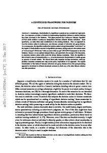
The latency of the first packets in the new flow from station 2 to station 4. The trigger scheme is used for all three runs
When a congestion notification arrives at an upstream station, the send value in the packet is remembered, but in the timer scheme it is not reacted upon until the timer goes off. Hence it may take a while until the station starts sending less traffic. Again this might be acceptable in a MAN or a WAN, but not when packet latency should be minimized. Our trigger scheme will act upon the received congestion notification immediately, and adjust the stations send rate to the received value at once. The latency of the packets from the run with the trigger scheme is almost not visible in figure 4. The trigger scheme latency is, however, also shown in figure 5 (250ns links – 3000B threshold). Figure 5 shows three results using the trigger scheme. Only packets traveling from station 2 to station 4 are plotted. The axes mean the same as in the previous figure, i.e. one point represents the latency of one packet (y-axis) and when it arrives at station 4 (x-axis). The bottom curve shows the same trigger result as in figure 4, but in a scale that shows the details. The figure also describes what happens if the latency between the stations increases in to 400 and 500 ns. In general it then takes longer for the packets to travel from station 2 to station 4. But it also takes longer for the congestion notification packet from station 2 to reach the source (station 0). In the bottom and the top plots, the passthru buffer threshold value is 3000 bytes. Hence the congestion notification is sent immediately when the passthru buffer size reaches 1500 bytes. At least three more 500 byte packets can then arrive before the station is congested. Remember that while the passthru buffer size is below the threshold, station 2 forwards every second packet from the passthru and the ingress buffer, so in fact the passthru buffer is at the same time emptied at “half speed”, making room for one or two more packets before the congestion mark is reached. During this time the congestion notification packet has had enough time to reach station 0, order it to stop transmitting and for the stop effect to be noticed at station 2, i.e. a full round trip time between stations 2 and 0. The conclusion is that the space in the passthru buffer between half the threshold value and the full threshold value was large enough to hold all packets arriving in this full roundtrip time. The stop order
6
was sent so early that station 2 never became congested. The bottom and the top plots in figure 5 show this; no packet had to wait exceptionally long. In the middle plot, however, we have decreased the threshold value to 2000 bytes, and then the passthru buffer more than fills up to the threshold while the congestion notification takes effect. In order for the plots not to come on top of each other, we ran that experiment with a link latency of 400ns. In this middle plot we see that the passthru buffer threshold is so small that before the congestion notification has had any effect, station 2 must serve the passthru buffer only, giving the first packet in the ingress buffer a really long latency (about 2.4 microseconds). The roundtrip time is obviously dependent on which station is sending too much. In the absolutely worst case it is a stations neighbor on one side that is for some reason sending packets all the way around the ring to the other side. In a more normal situation the longest round trip time is to a station opposite on the ring (half of the number of stations away on the ring). 250
Number of packets per 100 microseconds
From 0 to 6
From 2 to 4
200
150
100
50
0 0
5000
10000
15000
20000
25000
Time in microseconds Figure 6. The two competing flows – Timer scheme with original aging values We now turn to a more holistic view of the experiment. In figures 6, 7 and 8 we see the stability and the adaptation to changing traffic load of the timer and two versions of the trigger scheme. Results are shown both for the flow from station 0 to station 6 and for the flow from station 2 to station 4. The x-axis is the time; the complete experiment takes 22 milliseconds. With the timer scheme we ran the experiment for 26 milliseconds to see how the flow from 0 to 6 gradually increases after time 18 milliseconds when the flow from 2 to 4 stops. The y-axis shows the number of packets received every 100 microseconds. Figure 6 shows the algorithm with a 100 microseconds timer and the original aging parameters. Figure 7 shows a run when the fairness algorithm uses the trigger mechanism and one quarter of the original aging parameter values. Figure 8 shows the trigger scheme and one sixteenth of the original aging parameters.
7
Because station 0 has been sending for some time when station 2 starts sending, the fairness algorithm at first gives priority to station 2. This effect is seen in all three figures. In figure 6, station 2 gets to send alone for the longest time, in figure 8 for the shortest time. This is because the aging values are highest (new values have little effect) in the run plotted in figure 6 and smallest in the run plotted in figure 8. Figure 6 shows that the run with the timer scheme has fluctuations as long as both flows are active. This scheme is designed for MANs and WANs and will not stabilize so quickly. However we see that the “waves” are getting shorter with time, indication that they would probably soon smooth out if the two flows had kept on competing. We will discuss this briefly at the end of this section. Figure 7 and 8 both show great instabilities the first few milliseconds after the point where the two flows start competing. Figure 7 shows about 5 milliseconds of instabilities, while the run in figure 8, with the most aggressive parameter settings, has only 2 milliseconds of instability. After the instabilities both runs flattens out with almost an exactly 50-50 division of the bandwidth for a while. Then both runs show some temporary instability, before they for a short while again divide the bandwidth equally every 100 millisec.
Number of packets per 100 microseconds
250
0 to 6
2 to 4
200
150
100
50
0 0
5000
10000
15000
20000
Time in microseconds Figure 7. The two competing flows – Trigger scheme with one quarter of the original aging values When the flow from station 2 to station 4 terminates, the speed at which station 0 is increasing its send rate is quite different in the three figures. Here it is easy to see the effect of the low pass filters. The most conservative aging parameters explains the very slow rise of the sending rate after time 18 milliseconds in figure 6. Figure 7 is somewhere in between, but in figure 8 the aging parameters are so small that it seems like station 0 starts to send at full speed almost immediately after time 18 milliseconds. In order to investigate long-term stability, we changed the experiment and let the two flows continue to compete also after 18 milliseconds. With the timer and the original aging settings the flow from 0 to 6 had taken a total of 47 % of the bandwidth after 100 ms., 49 % at 150 ms. and 50% exactly at 200 ms. We ran this experiment with the trigger version of the algorithm and the most aggressive (the smallest values) aging settings. We counted the number of packets received after time 2 milliseconds, and found that the flow from 0 to 6 had taken 48% of the bandwidth after 30 ms, 49% of the bandwidth after 50 ms, and 50
8
% of the bandwidth after 100ms. Hence, both schemes converge; but the trigger scheme with aggressive aging values does so much quicker. 250
0 to 6
2 to 4
Number of packets per 100 microseconds
200
150
100
50
0 0
5000
10000
Time in microseconds
15000
20000
Figure 8. The two competing flows – Trigger scheme with one sixteenth of the original aging values 5. Conclusion and further work We have shown how a revised version of a possible RPR fairness algorithm can be modified and tuned so that it is suitable for a high speed network. In particular our implementation of triggers to handle congestion seems to be very promising. Also the use of more aggressive aging parameters (i.e. newer values have more weight) seems to be necessary in order to handle quick flow changes. The triggers and the aggressive aging parameters introduce some instability. The duration of these instabilities are short, and have no significance in the long run. They however deserve further study, because they could result in unexpected long communication delays between processes on different parts of the network. We have investigated and explained the relation between congestion threshold values and station-tostation latency. In particular we have seen that in LANs and high-speed networks with short distances between stations, passthru buffers that hold eight to twelve packets are large enough. The total latency that a packet experience is, in addition to the propagation delay on the links, the combined latency of waiting in the ingress buffer and all the passthru buffers under way. We would like to understand the trade off (if any) between the sizes of these buffers. We have not looked at the smoothing effects of passthru buffers either. In addition we would like to understand the aging parameters better. Hence, we need to run more experiments with our high speed network model in order to learn more. On a longer time scale we want to run execution driven simulations and see how a high speed network based on an RPR architecture runs concurrent applications.
9
Acknowledgement The author thanks Olav Lysne for making the initial simulation kernel and Arne Maus for help on how to best present the experimental results. REFERENCES 1. ANSI T1.105.01-2000: Synchronous Optical Network (SONET) - Automatic Protection. 2. H.R. van As: Major Performance Characteristics of the DQDB MAC Protocol. Telecommunications Symposium, 1990. ITS’90 Symposium Record, SBT/IEEE 1990 3. S. Breuer, T.Meuser: Enhanced Throughput in Slotted Rings Employing Spatial Slot Reuse. INFOCOM '94. Networking for Global Communications. IEEE. 1994 4. I. Cidon, L. Georgiadis, R. Guerin, Y. Shavitt: Improved fairness algorithms for rings with spatial reuse. INFOCOM '94. Networking for Global Communications. IEEE, 1994 5. I. Cidon, Y. Ofek: Distributed Fairness Algorithms for Local Area Networks with Concurrent Transmissions. In: Lecture Notes in Comp. Sci., Vol. 392, Springer, 1988 6. I. Cidon, Y.Ofek: MetaRing - A Full-Duplex Ring with Fairness and Spatial Reuse. IEEE Trans on Communications, Vol. 41, No. 1, January 1993. 7. K.C. Claffy: Internet measurements: State of DeUnion. http://www.caida.org/outreach/presentations/Soa9911 8. M.W. Garrett, S.-Q. Li: A study of slot reuse in dual bus multiple access networks. IEEE Journal on Selected Areas in Communications, Vol. 9 Issue 2, Feb. 1991 9. A. Grebe, C. Bach: Performance comparison of ATMR and CRMA-II in Gbit/s-LANs. SUPERCOMM/ICC '94, IEEE Int. Conf. on Serving Humanity Through Communications, 1994 10. IEEE Standard 802.5–1989, IEEE standard for token ring 11. IEEE Standard 802.6–1990, IEEE standard for distributed queue dual bus (DQDB) subnetwork 12. IEEE Standard 1596–1990, IEEE standard for a Scalable Coherent Interface (SCI) 13. ISO/IECJTC1SC6 N7873: Specification of the ATMR Protocol (V. 2.0), January 1993 14. I. Kessler, A. Krishna: On the cost of fairness in ring networks. IEEE/ACM Trans. on Networking, Vol. 1 No. 3, June 1993 15. W.W. Lemppenau, H.R.van As, H.R.Schindler: Prototyping a 2.4 Gbit/s CRMA-II Dual-Ring ATM LAN and MAN. Proceedings of the 6th IEEE Workshop on Local and Metropolitan Area Networks, 1993. 16. M.J. Marsan et al.: Slot Reuse in MAC Protocols for MANs. IEEE J. on Selected Areas in Communications. Vol. 11, No. 8, October 1993. 17. H.R. Muller et al: DQMA and CRMA: New Access Schemes for Gbit/s LANs and MANs. INFOCOM '90, Ninth Annual Joint Conference of the IEEE Computer and Communication Societies. IEEE , 1990 18. R.M. Needham, A.J. Herbert: The Cambridge Distributed Computing System. Addison-Wesley, London, 1982. 19. T. Okada, H. Ohnishi, N. Morita: Traffic control in asynchronous transfer mode. IEEE Communications Magazine , Vol. 29 Issue 9, Sept. 1991 20. D. Picker, R.D. Fellman: Enhancing SCI’s fairness protocol for increased throughput. IEEE Int. Conf. On Network Protocols. October, 1993. 21. F.E. Ross: Overview of FDDI: The Fiber Distributed Data Interface. IEEE J. on Selected Areas in Communications, Vol. 7, No. 7, September 1989. 22. I. Rubin, H.-T. Wu: Performance Analysis and Design of CQBT Algorithm for a Ring Network with Spatial Reuse. IEEE/ACM Trans on Networking, Vol. 4, No. 4, Aug. 1996. 23. D. Tsiang, G. Suwala: The Cisco SRP MAC Layer Protocol. IETF Networking Group, RFC 2892, Aug. 2000 24. S. Gjessing: Avoiding Head of Line Blocking using an Enhanced Fairness Algorithm in a Resilient Packet Ring. Submitted to IEEE 2002 International Conference on Communications.
10