... bounded by those two integers, a1 and b1 will be in the interval minfa0; b0g; maxfa0; b0g]. Similarly, c1 and d1 will be in the interval minfc0; d0g; maxfc0; d0g].
A Fast Algorithm for Designing Stack Filters y J. Yoo, K.L. Fong, J.-J. Huang, E.J. Coyle, and G.B. Adams III School of Electrical and Computer Engineering 1285 EE Bldg., Purdue University West Lafayette, IN 47907-1285
Abstract Stack lters are a class of nonlinear lters with excellent properties for signal restoration. Unfortunately, present algorithms for designing stack lters can only be used for small window sizes because of either their computational overhead or their serial nature. This paper presents a new adaptive algorithm for determining a stack lter that minimizes the mean absolute error criterion. The new algorithm retains the iterative nature of many current adaptive stack ltering algorithms, but signi cantly reduces the number of iterations required to converge to an optimal lter. This algorithm is faster than all currently available stack lter design algorithms, is simple to implement, and is shown in this paper to always converge to an optimal stack lter. Extensive comparisons between this new algorithm and all existing algorithms are provided. The comparisons are based both on the performance of the resulting lters and upon the time and space complexity of the algorithms. They demonstrate that the new algorithm has three advantages: it is faster than all other available algorithms; it can be used on standard workstations (SPARC 5 with 48MB) to design lters with windows containing 20 or more points; and, its highly parallel structure allows very fast implementations on parallel machines. This new algorithm allows cascades of stack lters to be designed; stack lters with windows containing 72 points have been designed in a matter of minutes under this new approach.
y
This work was supported in part by NSF Grants CDA-9015696, CDA-9422250, and CDA-9617388.
1
1 Introduction Stack lters are a class of nonlinear, sliding-window lters that satisfy a weak superposition property known as the threshold decomposition and an ordering property called the stacking property [1, 2, 3]. They are especially useful in such image processing applications as image enhancement [4, 5, 6] and detection of intensity edges in noisy images [7]. One of the main strengths of stack lters is the existence of an analytical technique for determining a stack lter that is optimal for estimation under the mean absolute error criterion [8, 9, 10]. Although these results provide a systematic approach for designing an optimal stack lter, knowledge of the joint threshold crossing statistics of the signal and noise process is required. Such knowledge is rarely available in practice, particularly in image processing applications. To minimize this problem, the adaptive stack ltering algorithms in [11, 12] were developed. These algorithms arrive at an optimal stack lter through an iterative approach that relies on training data. After each observation is taken from the training data, a table of decision variables is updated and the stacking property is then enforced on these variables. This incremental approach often requires that the algorithms make several passes over the training data before an optimal stack lter is reached. The algorithm in [12] is the faster of the two since it reduces the number of times the stacking property must be enforced. An alternative approach to the training of stack lters is provided by the FASTAF algorithm developed in [6, 13]. It uses one pass over the training data to determine an optimal Boolean lter and then projects this optimal lter onto the set of positive Boolean functions. A suboptimal implementation of this two-step procedure is provided in the form of a MATLAB algorithm in [13]. This algorithm is often faster than those in [11, 12], primarily because it requires only one pass over the training data. For small window sizes, such as 3�3, it is often extremely fast because the optimal Boolean lter is often already positive. Unfortunately, this friendly behavior of the data disappears as the window size grows to 4 � 4. In this case, the second step of the algorithm, which has high spatial complexity, can not be avoided. Unfortunately, both types of adaptive algorithms discussed above have limitations. The most critical is that the execution times and/or memory requirements of these algorithms increase much faster than linearly as a function of the window size of the lter being designed. Many hours are needed to design stack lters with 4 � 4 windows when the algorithms in [11, 12] are used. The FASTAF algorithm can only be used to design lters with up to 11-point windows when a standard workstation environment is used. In this paper, a new stack lter training algorithm is developed. It is related to the 2
algorithms in [11, 12], but di�ers in both the amount of training that takes place before the stacking constraint is enforced and in the method used to enforce this constraint. These di�erences allow the new algorithm to produce an optimal lter much more quickly than the algorithms in [11, 12]. They also enable this new algorithm to complete many passes over the training data before the projection step of the algorithm in [6, 13] nishes. With this new algorithm, a standard workstation can be used to quickly design stack lters with window sizes as large as 22 points. When used to design each lter in a cascade of two stack lters, this algorithm enables us to use very large windows. For example, if each lter in the cascade has a 5 � 5 window with the four corners removed, then the overall lter is a stack lter with a window containing 72 points. This ability to design stack lters with such windows has been critical to the success of the perceptually-optimal approach in [14]. This new algorithm is also highly parallel in nature. It allows very fast implementations to be developed when massively parallel machines, such as a MasPar MP-1, are available. To see how much a di�erence this would make, we developed such an implementation [15]. It enables us to design an optimal stack lter with a 25-point window in a matter of minutes. Section 2 of this paper reviews the properties of stack lters and current algorithms for the design of stack lters. Section 3 describes the new algorithm. Section 4 provides the proof of convergence for this new algorithm. Performance comparisons between current algorithms and the new algorithm are provided in Section 5.
2 Review of Optimal Stack Filtering Algorithms 2.1 Stack Filters Every stack lter possesses both the threshold decomposition property and the stacking property [1, 2, 3]. To de ne these properties, we must rst de ne the threshold decomposition of an image. Images will be assumed to take values on a lattice S . Each point in the lattice will be denoted by s 2 S . A gray scale image X with pixel values ranging between 0 and M may be represented as the sum of a series of binary-valued images,
X (s) =
M X l=1
xl(s);
where, for each l, the binary image xl(s) is obtained by thresholding X (s) at level l. Then, ( X (s) � l : xl(s) = 01;; X (s) < l Now let W be the size P window of the lter and let W (s) be the array of P points of the image that appears in the window W when its reference point is at position s. Then, 3
the window array WX (s) of the image X can be similarly thresholded, so that
WX (s) =
M X l=1
wX;l(s) :
Each stack lter Sf (�) is de ned by a Boolean function f (�) which satis es a stacking property: if the output of f applied to wX;l(s) is 1, then the output produced when f is applied to threshold level k must also be a 1 if k � l. More formally [1], for all k � l,
f (wX;k (s)) � f (wX;l(s)) :
(1)
A Boolean function has this property if and only if it is positive [16]. Mathematically the following superposition property also holds for the stack lter Sf based on the positive Boolean function f (�) with the window wX;l: M X
Sf (WX (s)) = Sf
l=1
!
wX;l(s) =
M X l=1
Sf (wX;l(s)) =
M X l=1
f (wX;l(s))
Due to these two properties, the operation of a stack lter Sf (�) is the same as the operation of the corresponding Boolean function f (�) for the thresholded binary inputs. Note that any Boolean function f of P variables can be represented by a length 2P decision vector D, D = (d ; d ; � � � ; d P ? ), where di = f (�i ) and �i is one of the binary sequences which correspond to the window arrays with P elements. Therefore, the problem of nding an optimal Boolean function is equivalent to nding the corresponding decision vector. 0
1
2
1
2.2 Optimal Stack Filtering Algorithms Since each positive Boolean function de nes a stack lter, a simple exhaustive search through the class is not feasible. Fortunately, the properties speci ed above led to useful algorithms for the design of optimal stack lters. The goal of these algorithms was to determine a stack lter which minimizes the mean absolute error between the output of the lter and some desired image, given a corrupted version of the desired image as input to the lter [10]. If X is the desired image, and X~ is the corrupted version observed by the lter, then, as proven in [8], the error to be minimized by proper choice of f (�) is: MAEf = E f j X (s) ? Sf (WX (s)) j g (
M X
~
)
= E j [xl(s) ? f (wX;l(s))]j = l=1
~
4
M X l=1
n
E jxl(s) ? f (wX;l(s))j ~
o
(2)
The second equality in the above set of equations follows from the threshold decomposition property of stack lters and the one-to-one relationship between stack lters and positive Boolean functions. The third equality follows from the stacking property of the positive Boolean function f (�) { all nonzero terms in the sum in the second equation have the same sign. Thus, the overall mean absolute error is simply the sum of the mean absolute errors on each of the levels of the threshold decomposition architecture. Our goal is to nd a positive Boolean function f (�) which minimizes the MAE in (2). From the form of the MAE expression, it is clear that an optimal f (�) makes the best decision at each location s as to whether the desired image value at s is less than l or not. The stacking constraints can be interpreted as forcing the decisions on di�erent threshold levels to be consistent with each other. The optimal ltering problem over the class of stack lters under the mean absolute error criterion can therefore be formulated as a zero-one integer linear program [8]: minimize Pi P ? Ci � di , subject to the constraints: 2 1 =0
di � dj if �i � �j ; di = 0 or 1:
(3)
where each coe�cient Ci depends on the joint statistics of the corrupted and the desired images. It can be interpreted as the cost incurred by f (�) for deciding a 1 when the binary sequence �i is in the lter window. Integer linear programming is NP-complete unless it has special structure [17]. Since the constraints in (3) can be rewritten as a TUM (totally unimodular matrix [17]), this zero-one linear program can be reformulated as the following linear program [8]: minimize Pi P ? Ci � di , subject to the constraints: 2 1 =0
di � dj if �i � �j ; 0 � dj � 1 for all j:
(4)
The linear programming formulation of the optimization problem has a very nice interpretation in terms of the behavior of the positive Boolean function f (�). The relaxed constraint in (4) implies that the lter is allowed to randomize its decision. The quantity di is thus the probability the lter puts out a 1 when the binary sequence �i is observed. The lter is thus allowed to make soft decisions [8]. There are two problems with this linear program. The rst is that the number of constraints on f implied by the stacking property grows exponentially in the window size of the 5
Image X
Noise corruption
∼ X
Windowing Input image
Desired image
W∼X
MAE adaptation
X
Sf f
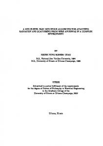
Figure 1: Block diagram of optimal adaptive stack ltering algorithm. lter. The second is that knowledge of the joint statistics of the image X and the process which corrupted it are required for computing the coe�cients of the cost function. The adaptive stack ltering algorithms developed in [11, 12] minimize these problems. Figure 1 illustrates the procedure for adaptive stack ltering. The desired image, X , and its noise-corrupted version X~ are used to train a positive Boolean function f to minimize the error between the lter output X^ and the desired image X when X~ is the input to the lter Sf . The algorithms, however, are quite slow and have thus been used to design lters with windows containing only 16 or fewer points. The problem is twofold. First, the stacking constraint is checked and enforced after each observation is made. Second, the adaptive algorithms can not be parallelized since only a single observation is taken between successive constraint enforcements. Consequently, many iterations are required to reach an optimal lter. The revised algorithm appearing in [12] eliminates some of this problem, but neither alters the nature of the algorithm nor decreases its complexity enough to permit lter design for windows with more than 16 points. The next section presents a new adaptive stack lter algorithm that converges much more quickly. It checks and enforces the stacking constraints only after many observations have been made, and enforces the stacking constraints in a new way.
3 New Adaptive Stack Filtering Algorithms Our e�orts to speed-up the algorithms described in [11] and [12] were ultimately abandoned because their unitary updates of each decision variable and the immediate correction of any stacking violation required that the update process be performed serially. This ruled out one of the best ways of speeding up an algorithm, which is to identify and exploit any parallelism inherent in the algorithm. One possible approach considered was the suboptimal algorithm presented in [18]. This 6
algorithm is e�cient, but it relies on the assumption that the windowed level-crossing statistics of the image tend to obey the stacking constraints. When they do, or nearly do, very few violations of the stacking constraint would be created during the observational phase of the training algorithm. The problem is that the assumption that few violations of the stacking constraint occur in natural images appears to apply only for 3 � 3 or smaller windows. The number of violations of the stacking constraint increases rapidly as the window size is increased, to the point that the assumption is clearly inappropriate for lters with 4 � 4 or larger windows. Our e�orts were therefore directed toward the development of a stack lter training algorithm that was fast, highly parallel, and guaranteed to converge to an optimal lter. The algorithm that resulted from these e�orts is described below. It always converges to an optimal lter and is dramatically faster than the algorithms provided in [11, 12].
3.1 Algorithm Summary When the window of the lter is of size P , the window array W (s) contains P pixels. The thresholded binary window array wl(s) at s therefore corresponds to exactly one of the 2P binary vectors of length P . Let �i, 0 � i � 2P ? 1, denote the ith of the 2P binary vectors of length P . Then a Boolean function f (�) is completely speci ed by the decision vector D, D = (d ; d ; � � � ; d P ? ), where di = f (�i), the ith decision variable, is the output of f (�) when �i is the input. Specifying D thus speci es the truth table of the Boolean function. In the algorithm described below, each decision variable can represent a soft decision { each can take on values in the interval [0,1] with resolution 1=N , where N is some positive integer. In this case di is interpreted as the probability that the lter f (�) outputs a 1 when �i is the input. For the sake of an e�cient implementation, each decision variable is rescaled so that it takes on integer values in [?N=2; N=2]. A decision vector with strictly hard decisions can be recovered from the rescaled soft decision vector at any time by thresholding it at 0. The algorithm described below begins by setting di = 0 for all i. If the binary sequence �i is observed at position s in a corrupted version of an image, it must be determined whether the true value of the pixel at position s in the uncorrupted image is 0 or 1. If it is 0, then di is decremented by 1; otherwise, di is incremented by 1. This is the same operation performed in the original adaptive stack ltering algorithm. Unlike the original algorithm, though, the stacking property will not be enforced on D after each observation. Instead, it will be checked and enforced only after L observations have been taken. When L corresponds to all possible observations from the training images, then, for each i, the number of increments performed on di is the cost incurred if the lter 0
1
2
1
7
outputs a 0 for each observation of �i. The number of decrements performed is the cost incurred if the lter outputs a 1 each time �i is observed. Thus, if di is thresholded at 0 to produce bi (bi = 0 if di � 0, else bi = 1 ), the result is the optimal hard decision bi for �i. Gather these hard decisions together in a binary vector B (L). This is the hard decision vector for a Boolean function which minimizes the mean absolute error between its output and the desired image when the corrupted version of that image appears at the input. Note, though, that B (L) usually will not specify a positive Boolean function. At this point some method for checking and enforcing the stacking property must be applied. Before stating the new method of enforcing the stacking constraint, we now summarize the algorithm:
� Step 1. Threshold the training data; obtain the window vectors of X~ and the desired noise-free image X .
� Step 2. Update the decision vector by using the thresholded binary training data over a period of L.
� Step 3. Check that the decision vector obtained from Step 2 satis es the stacking constraints. If there are any violations, then enforce the stacking property.
� Step 4. Go to Step 2 and continue the iteration process until the decision vector converges.
In general the update period L can be any arbitrary length and can even be time-varying. By changing L, we can control the trade-o� between the convergence rate and the nal mean absolute error. Allowing L to vary can reduce the number of iterations in the training process. Up to this point the new algorithm is similar to the current adaptive algorithms except for the exibility in choosing the length of the update period before checking and enforcing the stacking constraints. The next section describes how the new algorithm enforces the stacking constraint.
3.2 Checking and Enforcing the Stacking Constraint The adaptive algorithms described in [11] and [12] require an inherently serial update of their constrained decision vectors as their training routines progress. This serialization is the most serious problem with these algorithms. It makes training on large images or training lters with large window sizes a very lengthy process. To obtain a signi cant speedup, a new, parallel method of checking and enforcing the stacking constraints is required. 8
Step 1
i
αi
0 1 2 3 4 5 6 7
000 001 010 011 100 101 110 111
Step 2
0
1
D
D =D
Step 3
D
3 ~ D = D
2
~
d0 d1 d2 d3 d4 d5 d6 d7
d0 ~ d1 ~ d2 ~ d3 ~ d4 ~ d5 ~ d6 ~ d7
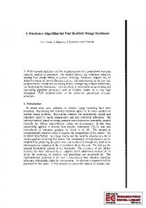
Figure 2: Parallel scheme for enforcing the stacking property for a size 3 window. The new algorithm given below achieves a high degree of parallelism. It resembles a merge-sort algorithm: pairs of vector elements are compared in parallel and a local stacking property [9] is enforced at each step until all related index pairs are compared and the new decision vector satis es the global stacking property. These operations are all applied to D, the vector of unconstrained soft decisions. Figure 2 shows how the algorithm would execute on the length 8 decision vector of a stack lter with a window of width three. In Figure 2, rst make the assignment D = D. Recall that D is ordered in such a way that di , the ith entry of D, is the (scaled) soft decision corresponding to the binary vector that is given by the binary expansion of the index i. Thus, d , which is at position 6 in D, is the (scaled) soft decision corresponding to the binary vector 6 = 110. To obtain D from D , successive pairs of entries of D whose subscripts di�er by a distance 2 = 1 apart are compared with each other. It is easy to see in the gure that each of these pairs corresponds to two binary vectors which are separated by a Hamming distance of 1 (they di�er in exactly one bit position). Any of these pairs which violate the stacking property are altered in such a way that the stacking property is obeyed. The constraints on how they can be altered will be speci ed later. Any pairs which do not violate the stacking property are left unaltered. To obtain Dk from Dk? , successive pairs of entries of Dk? whose subscripts di�er by a distance 2k? from each other are compared with each other for k = 1; 2; :::; P . Note that each of these pairs correspond to two binary vectors which are separated by a Hamming distance of 1 (they di�er in exactly one bit position) because of the ordering of the entries. Any pairs which violate the stacking property are altered so that they obey the stacking property. Any pairs which do not violate the stacking property are left unaltered. This process continues until k = P , where P is the window size of the lter. At this 0
6
1
0
0
0
1
1
1
9
point, the output for every binary vector will have been compared to the outputs for all binary vectors which are a Hamming distance of 1 away, and every locally observed violation of the stacking property would have been corrected. Thus, all entries of the vector obey the local stacking property de ned in [9]. This is necessary and su�cient for the sub-decision vector DP to satisfy the global stacking property [9]. Thus, if DP were thresholded at zero, the result would be a (hard) decision vector corresponding to a positive Boolean function. Therefore, at most P steps are required to check and enforce the global stacking constraint. From Figure 2 and the preceding description of this gure, it is obvious that massive parallelism exists in the new algorithm. The number of processors used in each stage is 2P ? for a lter with a window containing P points. Unlike the thresholding operations used to obtain the binary window vectors from the training data, enforcing the stacking property in this manner implies an extremely ne grained parallelism. If 2P ? processors are available, each one would at most fetch two units of data, make one compare and one enforcement, then store its data before having to fetch new data and repeat the process another P ? 1 times to ensure that D~ = DP satis es the global stacking property. In [15], the interprocessor communication required to support this operation was e�ciently implemented on the MasPar's XNet mesh communication network. Massively parallel data movements over the XNet mesh are the key to this e�ciency. At this point it is necessary to specify how the stacking constraint is enforced on pairs which violate the stacking property. It must be done in such a way that enforcements in later steps of the algorithm do not \undo" enforcements in earlier steps of the algorithm. 1
1
3.3 Schemes for Enforcing the Stacking Property The method for determining the new values of local pairs which violate the stacking property is now introduced. It seeks to preserve the statistical properties of the unconstrained soft decision vector, D(�). Since the value of each decision variable in D(�) corresponds to the added cost of making the wrong hard decision, whenever the soft decisions are altered in a stacking property enforcement operation, the new values of the decision variables should, as much as possible, re ect their original values. The method seeks to set each violating pair of decision variables to their statistical average, without resorting to oating point data types and without incurring any ill behavior that might be associated with roundo� errors. This constrains the algorithm to integer data types, so it satis es the condition of the rescaled soft decision vector mentioned earlier. Our solution is to use the ceiling and oor operators on the average of the decision variable pair. 10
In other words, for any decision variable pair which violates the local stacking property after the kth step: IF dik > dj k and j ? i = 2k , where the observed binary sequences �i and �j are Hamming distance 1 apart THEN � � � � k k k k di k = di dj and dj k = di dj , +
+1
+
+1
2
2
where for any real number x, the oor of x, bxc, denotes the greatest integer less than or equal to x, and the ceiling of x, dxe, denotes the least integer greater than or equal to x. The fact that the above enforcement scheme satis es the global stacking property is proved in the following theorem. As above, Dk (n) is the sub-decision vector of D(n) produced at the kth stage of the algorithm, and dik is the ith entry of Dk (n). The index n implies that the decision vector has been updated n times; it will usually be omitted in order to simplify the notation. Note that, for all k, every entry of Dk will be integer-valued.
Theorem 3.1 If at each stage of the algorithm described above, each pair dik and d�j k found� di k +dj k
to violate the stacking property is used to de ne di k+1 and dj k+1 such that di k+1 = and dj k+1 =
�
di k +dj k
2
�
2
, then the vector DP will satisfy the global stacking property.
Proof: (by induction) The window size 1 case is trivial; therefore, we will rst show the result is true for the window size 2 case. We will then show that if it is true for any window size P ? 1, then it is true for window size P . Proof for Window Size 2
To simplify the notation for the size 2 window, let the variables ak ; bk ; ck ; dk denote the decision variables d k , d k , d k , d k , respectively, for 0 � k � 2. In Step 1, we make comparisons between a and b , and between c and d , as shown in Figure 3. If therej is stacking violation between a and b , we enforce the stacking constraint k l m a b a b and b = . If there jis stacking violation between c and d , by setting a = k l m we enforce the stacking constraint by setting c = c d and d = c d . Therefore, at the end of the rst step of comparisons and enforcements we have: a � b and c � d . Since it is assumed that each decision variable can take on only integer values, and since the ceiling and oor of the average of two integers are bounded by those two integers, a and b will be in the interval [minfa ; b g; maxfa ; b g]. Similarly, c and d will be in the interval [minfc ; d g; maxfc ; d g]. 0
1
2
3
0
0
0
1
0+ 0 2
0
0
0
0+ 0 2
1
0
1
0+ 0
1
2
0
0+ 0
2
1
1
1
1
0
0
0
0
0
0
0
0
11
1
1
1
1
Step2
Step1 1
0
2
ai
D
D
D
00
a0
a1
a2
01
b0
b1
b2
10
c0
c1
c2
11
d0
d1
d2
Figure 3: Parallel scheme for enforcing the stacking property in the new algorithm; window size 2 case. Now consider Step 2 in Figure 3. Note that this step of the algorithm only needs to compare a to c and b to d . In this step, there are four possible cases relating to the global ordering of a ; b ; c ; d : Case (1): No stacking violations ) a � b � c � d or a � c � b � d . Case (2): Stacking violation between b and d ) a � c � d < b . Case (3): Stacking violation between a and c ) c < a � b � d . Case (4): Stacking violation between b and d , and a and c ) c < a � d < b or c � d < a � b . If Case (1) occurs, no further stacking violations exist and D (�) satis es the global stacking property. Consider Case (2), a � c � d < bj, in which b >l d violates the stacking property. k m d b d b ,d = , c = c and a = a . This To correct this violation we assign b = yields a � c � b � d , which satis es the global stacking property. In Case (3), c < a � b � d , thejordering a > lc violates the stacking property. To k m a c a c ,c = , d = d , and b = b . This correct this violation, we assign a = yields a � c � b � d , which satis es the global stacking property. Finally, in Case (4), c < a � d < b , or c � d < a � b , the orderings b > jd andk a > c lboth mviolate the stacking property. To correct these violations, we assign a = a c j k l m , c = a c , b = b d , and d = b d . This yields a � c � b � d (as shown in Figure 4) which satis es the global stacking property. As mentioned earlier, because all the decision variables are integers, a and c will be in the interval [minfa ; c g, maxfa ; c g], and b and d will be in the interval [minfb ; d g, maxfb ; d g]. Therefore, the results of Step 1, which ensured a � b and c � d , will not be changed by Step 2. In other words, we are guaranteed that a � b and c � d . Thus, 1
1
1
1
1
1
1
1
1
1
1
1
1
1
1
1
1
1
1
1
1
1
1
1
1
1
1
1
1
1
1
1
1
1
1
1
1
1
1
1
1
1
1
1
1
1
1+ 1 2
2
2
2
2
2
1
1
1
2
2
2
1
1+ 1 2
2
1
1+ 1
2
2
2
1
2
1
1
1
1
1
1
1
1
1
1
1+ 1
2
1+ 1
2
1+ 1
2
2
2
1+ 1
2
2
2
2
1
1
1
1
2
1
2
2
1
1
1
2
12
2
2
2
1
1
1
1
2
2
2
1
1
2
1
2
1
1+ 1 2
1
2
1
2
2
1
+
+
+ d1
d2
d1
d2
b1
c1
c2
b1
b2
d1
b1
b2
c1
c2
c1
+
d2 b2
+
+
d1
d2
b1
b1
b2
d1
a2
a1 b2 , c 2
or
a1
(1)
a1
c2
a1
a2
-
-
d2
b2
or
a1
b1
d2
c2
a2
c1
a2
a1
-
-
(2)
(3)
d1
c2 a2
c1
a2
c1 -
(4)
Figure 4: Four possible cases of stacking property violations in the window width 2 decision vector at the output of Step 1 (which ensures c � d , and a � b ). Case (1): no violations, two subcases; Case (2): violation between b and d ; Case (3): violation between a and c ; Case (4): violations between b and d , and a and c , with two subcases. 1
1
1
1
1
1
1
1
1
1
1
1
the stacking property is enforced globally for window size 2. Induction Step
Assume that this algorithm is valid for all window widths up through P ? 1 and consider a window of size P . After the (P ? 1)'st step of this algorithm is executed on the unconstrained decision vector for the window width P case, the decision vector can be divided into upper and lower halves. The upper half, corresponding to indices from 0 to 2P ? ? 1, has entries that satisfy the stacking constraints di P ? � dj P ? for 0 � i; j � 2P ? ? 1; i < j and i j = 1 , where the notation means i and j are separated by a Hamming distance of 1. The lower half, corresponding to indices from 2P ? to 2P ? 1, has entries that satisfy the stacking constraints diP ? � dj P ? for 2P ? � i; j � 2P ? 1; i < j and i j = 1. This follows since: each half of the decision vector after the (P ? 1)'st step is analogous to a window width P ? 1 decision vector after the (P ? 1)'st step; and the algorithm was assumed to be correct for window width P ? 1. During the P 'th step of the algorithm, the upper and lower halves of the decision vector produced by the (P ? 1)'st step are compared. In other words, the values d P ? ; d P ? ; : : :; d P ? ? P ? are compared to d P ? P ? ; d P ? P ? ; : : :; d P ? P ? , respectively. If there is a stacking violation between any local pair di P ? > dj P�? where i 0,
jjD~ (n + L) ? foptjj � jjD(n + L) ? foptjj + ~ (2M ) jjD(n) ? foptjj ? L
(14)
where M = ( 3L8+1 ). 2
Proof: If we take the square on the left term of (14), then jjD~ (n + L) ? foptjj = jjD~ (n + L) ? D(n + L)jj + jjD(n + L) ? foptjj +2(D~ (n + L) ? D(n + L)) � (D(n + L) ? fopt): 2
2
p
By Lemma 4.1, Lemma 4.2, Lemma 4.3, and the fact that a + b � a + jjD~ (n + L) ? foptjj � jjD(n + L) ? foptjj + jjD(n +(2LM) )? f jj opt 18
2
b a
2
2
if a > 0,
where M = ( L ). By using the triangle inequality and the following fact from [11] jjD(n + L) ? D~ (n)jj � L; 3 2 +1 8
we obtain where M = (
2
: jjD~ (n + L) ? foptjj � jjD(n + L) ? foptjj + ~ (2M ) jjD(n) ? foptjj ? L
L
3 2 +1 8
(15)
).
If jjD~ (n) ? foptjj is large enough { this is true when we have large N { then the last term in (14) will be small enough. Therefore, enforcing the stacking constraints does not move the decision vector away from an optimal positive Boolean function. Also, note that the bound in (15) is always less than the bound obtained for the LSC algorithm. In the LSC algorithm, the M in (15) is given by L . This implies that a decision vector moves to the optimal positive Boolean function faster than the decision vector in the LSC algorithm over a period of length L, as shown in Figure 5 if L � 1. By using the above lemmas and theorems, we can also show that, in the long term, the drift of the decision vector, D~ (n) is toward the optimal positive Boolean function. Since it is very similar to the LSC approach except for some di�erent values appearing in the bounds used in inequalities, we will not repeat the details of the proof. They can be found in Theorem 5.8 and Theorem 5.9 of [11]. 2
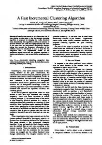
5 Experimental Results In this section, the convergence behavior of the new algorithm is examined. It is rst shown that the new algorithm converges faster than the adaptive algorithm presented in [12], which will hereafter be called the KL algorithm. Performance comparisons in terms of absolute error and training time are also made. The KL algorithm was used in all comparisons throughout this section. All stack lters used in this experiment were trained to restore noise-free original images from noisy images. We used an aerial photo of an air eld and the photo \Albert" shown in Figures 6 (a) and (b) as noise-free original images. The aerial photo is a 256 � 256, 8 bits/pixel image; Albert is a 512 � 512, 8 bits/pixel image. We generated noise-corrupted \aerial" and \Albert" images by using zero-mean additive impulsive noise with an occurrence probability of 0.1 an an absolute magnitude of 200. These noisy images, shown in Figures 6 (c) and (d), are denoted as AerialI 0:1 and AlbertI 0:1, respectively. All stack lters used 19
(a) (b) (c) (d) Figure 6: Images used in experiments: (a) Aerial photograph with 256 � 256 resolution, (b) Albert with 512 � 512 resolution, (c) AerialI 0:1, (d) AlbertI 0:1, The noisy images in (c) and (d) are corrupted by additive impulse noise with an occurrence probability of 0.1. in these experiments were trained by using noise-free and noisy aerial photos, and noise-free and noisy Albert images.
5.1 Convergence Behavior For comparisons of convergence behavior, 4 � 4 stack lters were designed with two di�erent algorithms: the KL algorithm and the new algorithm. In the new algorithm, we enforced the stacking property after every L updates of the decision vector, where L was chosen to be the total number of binary pixels in the training images. For instance, L is 256 � 256 � 256 for the aerial photo, and L is 512 � 512 � 256 for Albert. Figures 7 (a) and (b) show the convergence behavior of stack lters designed with the 20
3.05 4.4
KL Algorithm New Algorithm
4.2
2.95
Absolute Error
4
Absolute Error
KL Algorithm New Algorithm
3
3.8 3.6 3.4 3.2
2.9 2.85 2.8
3
2.75
2.8
2.7
2.6 2.65 0
5 10 15 Number of passes ( x L)
20
0
5 10 15 Number of passes ( x L)
20
(a) (b) Figure 7: Convergence behavior of 4 � 4 stack lters trained by the KL algorithm and the new algorithm. (a) When the training image was AerialI 0:1. (b) When the training image was AlbertI 0:1. noise-free and noisy aerial photos, and the noise-free and noisy Albert images, respectively. We applied the trained stack lters directly to the noisy training images, AerialI 0:1 and AlbertI 0:1, and measured the absolute error per pixel between each ltered output and the noise-free original image. The vertical and horizontal axes in Figures 7 (a) and (b) indicate the measured absolute errors per pixel and the number of passes over the training data, respectively. Each pass over the training data corresponds to L updates of the decision vector in both of the algorithms. As expected, the KL algorithm converges slowly for both training images. After 20L updates for the aerial photo, it is still converging while the new algorithm has already converged. However, in Albert, we can observe that both algorithms have converged after 20L updates. This is because the L used in Albert is 4 times greater than the L used in aerial photo. In other words, we have 4 times as many updates over the same number of cycles for Albert. Overall, Figure 7 indicates that the new algorithm requires fewer iterations than the KL algorithm to obtain an optimal lter.
5.2 Absolute Error and Training Time The comparisons of the new algorithm with the KL algorithm have shown that the new algorithm converges much faster. In this subsection, performance comparisons were made for di�erent window sizes on the basis of both absolute error and execution time. In most of the cases discussed below, measurements of execution time for both the KL algorithm and the new algorithm were based on their implementations on a SUN SPARC 5 21
KL
New Algorithm Number Training Number Training Time (seconds) Window of MAE Time of MAE Serial Parallel updates (seconds) updates Implemented Implemented 3�3 6L 2.93 103.9 1L 2.93 4.8 0.3 4�4 20L 2.70 1384.6 5L 2.68 96.2 19.6 5�5 na na na 1000L 2.37 na 12696.1 Table 1: Performance comparisons of the new algorithm with the KL algorithm for the image AerialI 0:1. Measurements were made for implementations of both the KL algorithm and the new algorithm on a SPARC 5 with 48MB or RAM, and for a highly parallel implementation of the new algorithm on a MasPar MP-1. with 48 MB of RAM. In some cases, however, measurements of execution time for the new algorithm were also made for an implementation on a MasPar MP-1 parallel computer. The details of this highly parallel implementation of the new algorithm can be found in [15]. This implementation allows stack lters with very large windows to be designed very quickly. We trained 3 � 3, 4 � 4, and 5 � 5 stack lters with the KL algorithm and the new algorithm. The images shown in Figure 6 were used as the training images, and all trained stack lters were directly applied to the noisy training images. The basis of the comparison for the two algorithms and the two implementations is the absolute error between each ltered output and the original noise-free image. The number of updates and the training time were then collected. Tables 1 and 2 show the number of updates, the absolute error per pixel between each ltered output and the original noise-free image, and the execution time of the algorithms for the aerial photo and Albert, respectively. The reasons that the training period is longer for lters with large windows are as follows. As the window size increases, more stacking violations are observed in the unconstrained decision vector. Therefore, after enforcing the stacking property at the beginning of the training process, the constrained decision vector deviates quite far from the unconstrained decision vector. This implies the loss of the statistical information contained in the unconstrained decision vector; more training is needed to compensate for this loss. The second reason is that many binary sequences may not be observed at all in the training images, especially for large window lters. For instance, a 5 � 5 lter has 2 � = 33:6 � 10 binary sequences in its decision vector, while a size 512 � 512 training image supplies at most 512 � 512 � 25 � = 6:6 � 10 binary patterns. In other words, a single standard size training image is not large enough when the lter window is large. The resulting large number of zero-valued elements a�ects other elements when the stacking property is enforced. Therefore, the constrained decision 25
6
6
22
KL
Window 3�3 4�4 5 � 5 without four corners 5�5
New Algorithm Number Training Number Training Time (seconds) of MAE Time of MAE Serial Parallel updates (seconds) updates Implemented Implemented 4L 3.25 281.8 1L 3.25 19.1 0.4 20L 2.72 4856.4 8L 2.72 177.5 73.7 40L na
2.45 na
19297.1 na
15L 1000L
2.43 2.20
11103.2 na
121.4 12822.0
Table 2: Performance comparisons of the new algorithm with the KL algorithm for the image AlbertI 0:1. Measurements were made for implementations of both the KL algorithm and the new algorithm on a SPARC 5 with 48MB or RAM, and for a highly parallel implementation of the new algorithm on a MasPar MP-1. vectors also deviate very much { at the beginning of the training process { after enforcement of the stacking property. For lter window sizes up to and including a 5 � 5 with the four corners removed, the KL algorithm converged slower than the new algorithm and required more training cycles to achieve the same MAE as the new algorithm. This is due to the serial technique the KL algorithm uses to enforce the stacking property, as described in Section 3. For a 5 � 5 window, we could not obtain results from the KL algorithm because of both the excessive time required for convergence and the large amount of RAM required to run the KL algorithm for large-window lters. For the new algorithm, we observed that the choice of L does not a�ect the convergence rate of stack lters much for smaller window sizes; for example, 3 � 3 and 4 � 4 windows. We have tried several passes of L, for L equals to one-half, one, two, and ve times the number of binary pixels in the training images. All of them converged at almost the same rate, if only because the algorithm itself converges very fast for small windows. Figure 8 shows the convergence behavior of stack lters for a larger window size { a 5 � 5 square with its corner deleted { for di�erent choices of L. The choice of L has less e�ect on the convergence for Albert than the aerial photo which can be explained with same reason mentioned before; namely, Albert has 4 times more pixels than the aerial photo. Overall, setting L equal to the total number of binary pixels in the training image is a good choice, regardless of the size of the image or the size of the lter window. The experiments described above indicate that the new algorithm requires fewer iterations in the training process to get lters of the same quality (the same absolute error). They also 23
6
Mean Absolute Error
6.5 6
L L L L
= 0.5N = N = 2N = 5N
5.5
Mean Absolute Error
7
5.5 5 4.5 4 3.5
5
L L L L
= 0.5N = N = 2N = 5N
4.5 4 3.5 3 2.5
3 2.5
2 0 5 10 15 20 Number of passes ( x L), N = 256x256x256
0 5 10 15 20 Number of passes ( x L), N = 512x512x256
(a) (b) Figure 8: Convergence behavior of the new algorithm for di�erent choices of L. The lter window is a 5 � 5 square with the four corner points removed. (a) When the training image was AerialI 0:1. (b) When the training image was AlbertI 0:1. indicate that each iteration requires much less time. Figure 9 shows the images obtained when optimal stack lters of various window sizes are applied the noisy images. As expected, the 5 � 5 stack lter result is the best. To test robustness, we designed a lter with Einstein and heavier impulse noise and then applied this lter to a noisy image that was di�erent than the one used to train the lter. Figure 10 shows the results of applying the new algorithm with di�erent window sizes. Note that the outputs are quite acceptable even for lters with small windows.
6 Comparison of New Algorithm and the FASTAF Algorithm In this section we compare the space and time complexities of the new algorithm in this paper with those of the the FASTAF algorithm described in [13]. All simulations were performed on a SUN SPARC 5 with 48 MB of RAM. Table 3 shows the spatial complexity required by the FASTAF algorithm and by the new algorithm. In computing the spatial complexity of FASTAF, we assumed an ideal memory allocation: each element of the stacking matrix occupied exactly one bit in memory. In computing the spatial complexity of the new algorithm, we assume 4 bytes are used to store each element of the updated decision vectors { this guarantees that no over ows will occur for even 1024x1024 images. Under these assumptions, the spatial complexity for FASTAF, when designing a lter 24
(a) (b) (c) (d) (e) (f) Figure 9: The outputs produced by lters designed by the new algorithm. (a) AerialI 0:1 after a 3 � 3 optimal stack lter. (b) AlbertI 0:1 after a 3 � 3 optimal stack lter. (c) AerialI 0:1 after a 4 � 4 optimal stack lter. (d) AlbertI 0:1 after a 4 � 4 optimal stack lter. (e) AerialI 0:1 after a 5 � 5 optimal stack lter. (f) AlbertI 0:1 with 5 � 5 optimal stack lter. 25
(a) (b) (c) (d) (e) (f) Figure 10: (a) Output of a 3 � 3 stack lter designed by the new algorithm for Albert corrupted by 20% impulsive noise with magnitude of 200. (b) Output of a 3 � 3 stack lter designed by the new algorithm for Aerial corrupted by 20% impulsive noise with magnitude of 200. (c) Same as (a) but with a 4 � 4 window. (d) Same as (b) but with a 4 � 4 window. (c) Same as (a) but with a 5 � 5 window. (d) Same as (b) but with a 5 � 5 window. 26
with a window of size n, is 2 n. The true worst case complexity of FASTAF is actually 2 n, which occurs when all the binary vectors are in the undecided set. This latter case is rare, but can be approached in cases in which the noise tends to complement the image. Because of this high spatial complexity, the maximum window size we are able to implement for FASTAF on the SPARC 5 was 11 points. This is admittedly due in part to MATLAB's use of double precision for all calculations. In contrast, the spatial complexity of the new algorithm in this paper grows as 2 � 2n . Filters with windows containing as many as 22 points can thus be designed on the target SPARC 5. We now provide execution-time comparisons of the FASTAF and new algorithm. The following conditions were imposed upon these comparisons: 2
4
+5
� The window size was restricted to 11 because the FASTAF algorithm would not execute on the target SPARC 5 for larger windows.
� Our goal is to concentrate on the duration of the training procedures of the two algo-
rithms. We thus do not count the time used by the FASTAF algorithm to set up the stacking matrix. Note, though, that the time to set up this matrix exceeded the time to complete the training procedure for a window of size 11.
� The full FASTAF algorithm actually involves two steps. The rst is the training step
in which an optimal Boolean function is found and an initial, possibly suboptimal projection of this Boolean function onto the set of positive Boolean functions is computed. In most cases, this projection results in a lter which is either optimal or very close to optimal. When the projection result is poor, a subsequent linear program must be used to obtain an optimal lter. In all of the comparisons provided here, the linear program step is skipped; those cases in which it would have been needed to reach an optimal lter are noted. The need for the linear program step would, of course, signi cantly increase the time required by the FASTAF algorithm to reach an optimal lter.
� We also modi ed the MATLAB implementation of FASTAF given in [13] to remove some redundant steps. This sped it up by a factor of nearly 5 for a window of size 11.
Table 4 shows the average training time required to reach an optimal stack lter by the new algorithm and the time required for FASTAF algorithm (without its additional linear programming step). The new algorithm took much less time to reach an optimal stack lter. In more than 80 percent of the test cases tried, the new algorithm required one training pass lasting only 7 seconds to reach an optimal lter. 27
New Algorithm FASTAF Memory occupied (bits) 2n 2n +5
2
Table 3: Comparison of the spatial complexities of the new algorithm and the FASTAF algorithm. It is assumed that the optimal memory allocation of one bit for each element in the stacking matrix is used for the FASTAF algorithm. The window size is n. New Algorithm FASTAF Average Training Time (seconds) 20.3 126.4 Table 4: Performance comparisons of the new algorithm with the FASTAF algorithm when the FASTAF algorithm actually produces an optimal stack lter. The new algorithm always yields an optimal lter. Measurements were made by implementing both algorithms in MATLAB on a SUN SPARC 5 with 48MB of memory. The window size was 11. Table 5 shows the performance of the FASTAF and new algorithms in a case in which the behavior of the noise leads to a large number of binary vectors in the undecided set of the FASTAF algorithm. In this case, the linear programming step of the FASTAF algorithm is required if the algorithm is to reach an optimal stack lter. We do not provide the time required to implement the LP step of FASTAF since the new algorithm converged to an optimal lter before the training step of FASTAF completed. Note that after ve training loops that the error of the new algorithm is close to the nal error for FASTAF, but less time was required to reach that level of error. Furthermore, after 20 loops, the new algorithm had reached an optimal lter, and nished faster than FASTAF. The conclusion is that the new algorithm introduced in this paper is better than FASTAF because it yields an optimal stack lter in signi cantly less time and it has signi cantly lower spatial complexity. The lower spatial complexity allows lters with much larger windows to be designed. For the target SPARC 5, windows twice as large { 22 versus 11 { can be designed if the new algorithm is used instead of FASTAF. Thus, due to di�erences in complexity and the fact that FASTAF does not, unlike the new algorithm, always reach an optimal lter, the new algorithm is preferable. When the parallel structure of the new algorithm is also taken into account, the advantages of the new algorithm become even greater.
28
New Algorithm FASTAF Number of Absolute Training Time Absolute Training Time updates Error (seconds) Error (seconds) 1L 8.03 9.1 5L 7.96 34.3 7.96 150.8 20L 7.95 134.4 Table 5: Performance comparisons of the new algorithm with the FASTAF algorithm for the image Einstein corrupted with both additive impulsive noise and line drop-out noise. The window size is 11. Measurements were made by implementing the algorithms in MATLAB on a SUN SPARC 5.
7 Conclusion In this paper, we proposed a new, adaptive stack ltering algorithm which signi cantly accelerates the training process. It retains the iterative nature of previous adaptive algorithms but reduces the number of iterations required in the training process. The convergence of the new algorithm was proven, and it was shown to be signi cantly faster and more reliable than earlier iterative training algorithms and the newer FASTAF algorithm. The importance of this new algorithm for designing stack lters is the many new experiments that can be conducted. Experiments with stack lters with 16 or fewer points in the window can now be carried out in a matter of minutes or seconds. Experiments with optimal lters with windows as large as 25 points are possible for the rst time. As a concrete example, this new algorithm was used in [4] to explore the possibility of using a weighted version of the mean absolute error criterion to produce lters that are perceptually optimal. The images in this paper can be viewed at: http://www.ecn.purdue.edu/~coyle
References [1] P. D. Wendt, E. J. Coyle, and N. C. Gallagher, Jr., \Stack lters," IEEE Trans. Acoust. Speech, Signal Processing, vol. 34, pp.898-911, August 1986. [2] J. P. Fitch, E. J. Coyle, and N. C. Gallagher, Jr., \Median ltering by threshold decomposition," IEEE Trans. Acoust., Speech, Signal Processing, vol. 32, pp. 1183-1188, December 1984. [3] J. P. Fitch, E. J. Coyle, and N. C. Gallagher, Jr., \Threshold decomposition of multidimensional rank order operators," IEEE Trans. Circuits Syst., vol. 32, pp. 445-450, May 1985. [4] J.J. Huang and E.J. Coyle, "The e�ect of changing the weights in the mean absolute error criterion upon the performance of stack lters," Proceedings of the 1995 IEEE Workshop on Nonlinear Signal Processing, pp. 887-890, Halkidiki, Greece, June 1995. 29
[5] L. Yin, R. Yang, M. Gabbouj, and Y. Neuvo, \Weighted median lters: a tutorial," IEEE Trans. on Circuits and Systems II: Analog and Digital Signal Processing, vol. 43, no. 3, pp. 157-192, March 1996. [6] I. T�abu�s, \Training and model based approaches for optimal stack and Boolean ltering with applications in image processing," Ph.D. Thesis, supervised by Prof. M. Gabbouj, Tampere University, Finland, 1996. [7] J. Yoo, C. A. Bouman, E. J. Delp, E. J. Coyle, \ The nonlinear pre ltering and di�erence of estimates approaches to edge detection: application of stack lters," CVGIP: Graphical Models and Image Processing, vol. 55, no. 2, pp. 140-159, March 1993. [8] E. J. Coyle and J.-H. Lin, \Stack lters and the mean absolute error criterion," IEEE Trans. Acoust., Speech, Signal Processing, vol. 36, pp. 1244-1254, August 1988. [9] J. -H. Lin and E. J. Coyle, \Minimum mean absolute error estimation over the class of generalized stack lters," IEEE Trans. Acoust., Speech, Signal Processing, vol. 38, pp. 663-678, April 1990. [10] E. J. Coyle, J.-H. Lin, and M. Gabbouj, \Optimal stack ltering and the estimation and structural approaches to image processing," IEEE Trans. Acoust., Speech, Signal Processing, vol. 37, pp. 2037-2066, December 1989. [11] J.-H. Lin, T. M. Sellke, and E. J. Coyle, \Adaptive stack ltering under the mean absolute error criterion," IEEE Trans. Acoust., Speech, Signal Processing, vol. 38, pp. 938-954, June 1990. [12] J.-H. Lin and Y.T. Kim, \Fast algorithms for training stack lters," IEEE Trans. Signal Processing. vol. 42, no. 4, pp. 772-781, April 1994. [13] I. T�abu�s, D. Petrescu, and M. Gabbouj, \A training framework for stack and Boolean ltering { fast optimal design procedures and robustness case study," IEEE Trans. on Image Processing, vol. 5, no. 6, pp. 809-826, June 1996. [14] J.J. Huang and E.J. Coyle, \On the design of a perception-based error criterion and its use in the theory of optimal stack ltering," preparing for submit to IEEE Trans. on Image Processing. [15] K. L. Fong, J. Yoo, G. B. Adams III, and E. J. Coyle, \A parallel stack lter algorithm and its implementation on the MasPar MP-1," manuscript in preparation. [16] E. N. Gilbert, \Lattice-theoretic properties of frontal switching functions," J. Math Phys., vol. 33, pp. 57-67, April 1954. [17] C. Papadimitriou and K. Steiglitz, Combinational optimization: algorithms and complexity, Englewood Cli�s, NJ: Prentice-Hall, 1982. [18] B. Zeng, M. Gabbouj, and Y. Neuvo, \A uni ed design method for rank order, stack, and generalized stack lters based on classical Bayes decision," IEEE Trans. on Circuits and Systems, vol. 38, no. 9, pp. 1003-1020, September 1991.
30