A Fast Cutting-Plane Algorithm for Optimal Coalescing Daniel Grund1?? and Sebastian Hack2 1
2
Department of Computer Science, Saarland University
[email protected] Department of Computer Science, University of Karlsruhe
[email protected]
Abstract. Recent work has shown that the subtasks of register allocation (spilling, register assignment, and coalescing) can be completely separated. This work presents an algorithm for the coalescing subproblem that relies on this separation. The algorithm uses 0/1 Linear Programming (ILP), a general-purpose optimization technique, to derive optimal solutions. We provide the first optimal solutions for a benchmark called “Optimal Coalescing Challenge”, i.e., our ILP model outperforms previous approaches. Additionally, we use these optimal solutions to assess the quality of well-known heuristics. A second benchmark on SPEC CPU2000 programs emphasizes the practicality of our algorithm.
1
Introduction
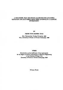
Coalescing is an important compiler optimization that removes useless copy instructions from a program to improve its performance. Because it needs information about assigned registers it is commonly performed as a subtask of register allocation besides spilling and register assignment. The first published coalescing heuristic [1] did not know about the negative influence of aggressive coalescing on spilling. Later approaches discovered these effects and restricted coalescing [2,3] or avoided harmful cases by partial undoing [4]. Latest work [5] suggests to perform register allocation while the program is in SSA form (static single assignment). The chordality of the SSA programs’ interference graphs allows for an allocation scheme in which each subtask needs to be processed only once, see Figure 1. For the same reason the effects of coalescing on the colorability of an already colored interference graph can be predicted precisely. Our main contribution is an algorithm for optimal coalescing using 0/1 linear programming (ILP) that outperforms previous approaches, e.g., most recently [6]. Basically, the algorithm only relies on the strict separation of spilling ??
Partially supported by the German Research Foundation (DFG) GK 623.
2
Daniel Grund, Sebastian Hack
Spill
IFG
not k-colorable
Coalesce (a)
Color
Spill
Coalesce
Color
IFG
SSA destruction (b)
Fig. 1. Rough register allocation schemes: (a) Traditional, “iterative” Chaitin style allocator. (b) “Sequential” SSA form allocator. For spilling and coloring an interference graph is not strictly necessary.
and coalescing, although there is one step that can be handled more efficiently for chordal graphs. Optimization of the ILP solution process is key to obtain suitable solution times. We present optimizations including a preprocessing that reduces the problem size, cutting planes pruning the search space as well as alternative ILP constraints that are most easily generated for chordal graphs. We use a set of interference graphs published by Appel [7] to assess the speed of our algorithm. Our algorithm is the first to actually compute optimal solutions thereby outperforming Appel’s approach [6]. Furthermore, we use the obtained solutions to absolutely qualify coalescing heuristics presented in [8] and [7] and the well-known ones presented in [3] and [4]. I.e., we judge them by how close they are to the optimum; we do not ask how much they improved some objective function but how much potential is left over. The next section gives the necessary concepts from graph theory and integer linear programming. Section 3 describes in detail all sources of copy instructions (especially the handling of φ-functions) and defines the coalescing problem in terms of an augmented interference graph. The main contribution is presented in Section 4: The first part deals with the basic ILP model while the second part presents the optimizations. The benchmark results are contained in Section 5. Finally, Section 6 contrasts this paper to related work and Section 7 concludes.
2
Foundations
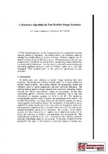
Concepts from graph theory: A chord is an edge connecting two non-adjacent nodes on a cycle. A cycle with k nodes and without chords is called a k-hole. A graph is called chordal if it does not contain any k-holes for k ≥ 4. A clique is a completely connected subgraph. An alternative characterization of chordal graphs can be given iteratively: A clique is a chordal graph. Gluing together two chordal graphs such that the shared nodes are a clique is again a chordal graph. More precisely, G = G1 ∪ G2 is chordal if the subgraphs Gi are chordal and G1 ∩ G2 is a clique.
3
Ch ord
A Fast Cutting-Plane Algorithm for Optimal Coalescing
(a)
(b)
(c)
(d)
Fig. 2. Concepts from graph theory related to chordality: (a) A chord in a cycle building a 4-hole and a 6-hole. (b) Two non-chordal graphs. (c) Some cliques. (d) A chordal graph constructed with the cliques of (c).
Integer linear programming (ILP) is the problem of maximizing or minimizing an objective function subject to (in)equality constraints and integrality restrictions on a (sub)set of variables. In general, solving an ILP is N P hard, but in practice even large instances can be solved. Let P = {x | Ax ≥ b, x ∈ Rn+ }, c ∈ Rn , b ∈ Rm , A ∈ Rm×n . Then ILP is the problem: min f = cT x,
x ∈ P ∩ Zn
The set P is called the feasible region. P is called integral if it is equal to the convex hull PI = conv(P ∩ Zn ) of the integer points I. In case of an integral feasible region, an P optimal solution of the ILP can be efficiently PI computed by solving the LP relaxation of the I problem by dropping all the integrality constraints. The figure to the right illustrates the coherence of these sets. Closing the gap between the feasible region and the convex hull by an efficient problem formulation or by adding additional constraints/cuts helps ILP solvers to find good or optimal solutions more quickly. In contrast to constraints cuts do not rule out any feasible integer points. For more details on (I)LP refer to [9,10].
3
The Problem
Let us first briefly summarize register allocation for SSA-form programs as described in [5] and illustrated in Figure 1. First, the register pressure is reduced to the number of available registers k by selecting certain abstract values and generating spill code for them. Then the actual assignment of registers takes place by performing a walk over the dominance tree of the program. Coalescing is an optional optimization that may be disregarded. If applied, it may either improve a given coloring or it can subsume coloring by combining the two phases. At last, the SSA form is destructed by replacing the φ functions with register permutations. For the details we have to refer to [11] or most recently to [8].
4
Daniel Grund, Sebastian Hack
In such a setting, the starting point for coalescing is a k-colored chordal interference graph G = (V, E). To express the subjects of coalescing we add a second type of undirected, so called affinity edges to the graph yielding G = (V, E, A). An affinity edge is assigned an additional positive weight that represents the penalty incurred whenever the two incident nodes have different colors. Thus, coalescing is the optimization problem to color as many affinity pairs as possible with only one color each, while retaining a correct coloring. In the following, we list the origin of these edges (how they emerge) and describe their construction. φ functions represent control-flow-dependent data flow. Because there is no immediate hardware support for this abstraction, one has to realize them with suitable instruction sequences. This is called SSA destruction. All prior SSA destruction algorithms insert sequences of copy instructions in the predecessor blocks to implement the behavior of the φ functions and (try to) merge nodes in the resulting interference graph to reduce the number of copy instructions. But as described in [5], inserting sequences of copy instructions is in general neither desirable (may destroy chordality) nor possible (may raise register demand). Instead, the intermediate step of implementing φs with permutations respects the requirement that all φs in a basic block must be carried out simultaneously. Thus, the semantics of φ functions in the same basic block may be described as the simultaneous permutation of registers contents on the incoming control flow edges. That is why φ functions should or must be replaced by permutations that are finally implemented by copy or swap instructions. Regarding coalescing, our approach is to add an affinity edge for each operand of a φ function connecting it to the result of the φ. Coalescing may assign such a pair of nodes the same color, in which case no value movement is necessary. When SSA destruction inserts permutations, the prior optimization has already maximized the number of fixed points of these permutations. Figure 3 shows an exhaustive example. Register constraints, the requirement that the assignable registers of certain arguments or results of an instruction are limited to a subset of all registers, are another source of permutations.3 But as they are beyond the scope of this paper, we will not elaborate this topic deeply. In general, completing the coloring of a graph with pre-colored nodes is N P complete, even for chordal graphs [12]. But if each color is used only once by the pre-coloring the problem becomes easy for chordal graphs. As shown in Figure 4, we insert a permutation in front of each instruction having a register constraint on one of its arguments or results (e.g., mul or div on IA32 architecture). Therefore, every live range ends before such an instruction and the interference graph is split into several unconnected components, each containing every constraint color only once. To maximize the number of fixed points of a permutation of size k we add k affinity edges to the interference graph connecting the corresponding nodes of a permutation. 3
Permutations for register constraints are inserted before coloring, permutations for φ functions during SSA destruction, after coalescing.
A Fast Cutting-Plane Algorithm for Optimal Coalescing
ar4 = . . .
br3 = . . . cr2 = . . .
5
ar4 = . . . br3 c » 0r2 – br2 c0r3 a ¯r1
dr1 = . . . er2 = . . .
= ... = . . .» – br3 = σ1 cr2 = ar4
dr1 – » er2 d0r1 0 er2 e¯r3
= ... = . . .» – dr1 = σ2 er2 = er2
3 2 3 xr1 a ¯r1 d0r1 4 yr2 5 = Φ 4 b0r2 e0r2 5 zr3 c0r3 e¯r3 . . . = ar4
2
3 2 3 xr1 ar4 dr1 4 yr2 5 = Φ 4 br3 er2 5 zr3 cr2 er2 . . . = ar4
2
(a)
(b) a b
c x
y
d
e
z (c)
Fig. 3. Connection between Φs, permutations, and SSA destruction. (a) Example SSA program. The subscripts of the variables denote the assigned registers. (c) Interference graph of the program in (a) with dashed affinity edges ([a, x] was left out due to infeasibility). (b) The program after SSA destruction without prior coalescing. The abstract values v 0 hold the results of the permutations. σ1 is inserted to swap the registers of b and c. σ2 is the identity function. Its insertion is not strictly necessary. Now the Φ function can be omitted because the registers of arguments and corresponding results match. In addition this example contains all details and special cases one has to consider: The abstract values v¯ are introduced to duplicate values. The value of a must be duplicated because it is used at the end of the last basic block and thus interferes with x. The value e must be duplicated because upon entering the last block the value must be present in two registers (y and z). The duplicated value e¯ could be assigned to y or z. Since the registers of e and y match, e¯ is assigned to z.
6
Daniel Grund, Sebastian Hack .. . (a0 , b0 , . . .) = σ(a, b, . . .) x = op(a0 , b0 ) d = c0 + b0 (a)
r1 r2 r3 r4 r5 r6
r2 r1 r5 r3 r4 r6 (b)
(c)
Fig. 4. (a) Before every register-constrained operation op we permute by σ all abstract values (a, b, . . .) live at that position. (b) Cutout of an interference graph showing nodes at such a program point: The upper nodes correspond to the original abstract values (a, b, . . .) to permute, the lower nodes correspond to the results (a0 , b0 , . . .) of the permutation. Some of the lower nodes are subject to register constraints imposed by op. The affinity edges connect each v with its v 0 . Thus, coalescing will maximize the number of fixed points of σ, and a lower number of instructions will result when generating code for σ. (c) The permutation corresponding to the register assignment in (b).
Register identity in two-address code, the requirement that the same register must be assigned to the first operand and the result of an instruction, can be seen as a register constraint. But it is handled differently to keep the number of affinity edges small. We simply express the wish to have the result and the first operand in the same register by adding an affinity edge between the two corresponding nodes. If this wish is declined one can still fulfill this constraint by generating suitable code not considered here.
4
Optimal Solutions using ILP
In this section, we will develop a 0/1-LP (an ILP with all variables being binary) to solve coalescing problems represented by a graph G = (V, E, A) as introduced in Section 3. The idea is to use a standard ILP to model the graph-coloring problem and to introduce separate variables to express the target function to optimize. Finally, one has to interrelate these two components with additional, well chosen constraints. 4.1
Formalization
Let us first model the correct coloring of the interference graph G = (V, E, A) with k available colors. For each node vi ∈ V , we add k binary variables xi1 . . . xik to the model (we know that the graph is k-colorable), where xic = 1 if and only if node vi has color c. ToPexpress that each node gets assigned exactly one color, k we add the constraints c=1 xic = 1. For each interference edge eij ∈ E connecting two nodes vi and vj we must assure the nodes get assigned different colors. This is simply achieved by adding xic + xjc ≤ 1 for each color c. So far this corresponds to Appel’s formulation [6].
A Fast Cutting-Plane Algorithm for Optimal Coalescing
7
Now let us focus on the affinity edges. First we model the objective function: For each affinity edge aij ∈ A with the positive weight wij , we add the summand wij yij to the objective function being minimized. The binary variables yij shall be 1 if and only if the adjacent nodes vi and vj have different colors. Therefore the costs wij are incurred iff yij = 1 iff the two nodes have different colors. So far, the last property is not modelled, yet, because the optimality variables yij are completely unconstrained. We have to interrelate these variables with the coloring variables. All the variables yij are optimized to 0 automatically, if possible. Thus, we only have to take care of the case where two affinity nodes have different colors. In this case we force yij to be 1 with the following constraints: yij ≥ xic − xjc for each color c. If the two involved nodes have different colors, there exists an inequality constraint with the right hand side evaluating to 1, and therefore enforcing yij = 1. If the two nodes have the same color, all right hand sides evaluate to 0 and the variable yij is effectively not constrained by these constraints and will be minimized to 0. To sum things up, here is the complete model: P min f = aij ∈A wij yij Pk where vi ∈ V c=1 xic = 1 xic + xjc ≤ 1 (vi , vj ) ∈ E, c = 1 . . . k yij ≥ xic − xjc (vi , vj ) ∈ A, c = 1 . . . k yij , xic ∈ {0, 1} 4.2
Optimizations
Although the above model yields correct results, even the runtimes of industry strength ILP solvers are unsatisfactory as we will show later in the measurements section. Therefore we increase the performance of the solution process by taking the following measures. Data Size Reduction The first optimization is a preprocessing that takes place before the graph is transformed to an ILP. We unburden the ILP solver by reducing the problem to its core, thereby reducing the number of variables and constraints it has to deal with. More precisely, we want the solver to only think about the parts of the graph related to affinity edges, and complete the optimal partial coloring by a standard algorithm. Remember that a node with degree strictly less than k (insignificant degree) can be colored regardless of the colors assigned to its neighbors and can be removed from the graph. This elimination was already used in Chaitin’s allocator [1]. With this in mind, we remove a maximum number of nodes from the graph that satisfy the following conditions: – The node removed is not incident with an affinity edge. – The node is not subject to any register constraints. – The node has insignificant degree in the current graph.
8
Daniel Grund, Sebastian Hack
Thus, we end up with a maximal prefix of an elimination order. The remaining nodes are the core of the problem that is solved by the ILP solver. Afterwards, the removed nodes are colored in reverse order resulting in a global optimal solution. Note, that this reduction can split the graph into unconnected components. Solving each connected component separately reduces the total solution time significantly. Clique Inequalities The second optimization modifies the ILP model. It uses the well known clique inequalities [10] to model the interference edges. Given an interference clique v1 . . . vn , it is clear that each color can appear at most once in this clique. Thus, instead of modeling each of the interference edges Pn one by one, we replace the O(n2 ) constraints xic + xjc ≤ 1 with just one i=1 xic ≤ 1 per color. If the clique is of size k such constraints are always satisfied at equality. Thus, one can demand equality to add more explicit knowledge to the model. In general, computing a minimum clique cover is N P complete [13]. However, there is an efficient O(|V | + |E|) algorithm for chordal graphs [14]. For arbitrary graphs one must fall back to a heuristic computing some clique cover. Reverse Affinity Cuts As we have seen, only one of the two possible sets of inequations yij ≥ xic − xjc and yij ≥ xjc − xic is necessary to model an affinity edge [i, j] ∈ A. But the other one can be used to tighten the LP relaxation. Consider the following example with three colors. The fractional values of the x variables might occur as a solution of the LP relaxation: y ≥ 0.4 − 1.0 y ≥ 0.3 − 0.0 y ≥ 0.3 − 0.0 Effectively this only yields y ≥ 0.3. Adding all inequations with switched minuend and subtrahend results in y ≥ 0.6. Path Cuts In some sense, an ILP solver is a generic piece of software. As described in Section 2 supporting it with cuts that describe problem specific knowledge can lead to better performance. The last two optimizations provide such cuts: They encode a lower bound for certain subsets of affinity edges. The first class of cuts uses the contradictoriness of affinity and interference edges. Affinity edges represent the wish to assign the same colors, but interference edges are hard constraints for different colors. Consider a path of affinity edges where only its ends are connected by an interference edge, e.g., Figure 5: Clearly, one of the affinity edges must break, because along the path the coloring must change at least once. To be precise: Definition 1 (Affinity-connected) Let the graph G = (V, E, A). Two nodes a, b ∈ V are affinity-connected, if a and b are connected by a path of affinity edges and no inner nodes of this path are connected with an interference edge: ∃v1 , . . . , vn ∈ V :
A Fast Cutting-Plane Algorithm for Optimal Coalescing
– – – –
9
a = v1 , b = vn vi = vj ⇒ i = j ∀1 ≤ i < n : (vi , vi+1 ) ∈ A ∀1 ≤ i < j ≤ n : (vi , vj ) ∈ E ⇒ {vi , vj } = {a, b}
Lemma 1 (Path Cut) If two nodes interfere and are affinity-connected with Pn−1 the path v1 , . . . , vn the following inequation holds: i=1 yi,i+1 ≥ 1 Clique-Ray Cuts Definition 2 (Clique Ray) A subgraph consisting of an interference clique C = {v1 , . . . , vn } and a node a ∈ 6 C with affinity edges to all v ∈ C is called a clique ray. At first, this compound of cliques and affinity edges illustrated in Figure 5 may seem very special. But this pattern occurs in real problems, e.g., if one and the same variable is used multiple times in different φ functions in the same basic block at the same argument position. Due to the simultaneous execution of all φ functions in a basic block, all results interfere pairwise and form an interference clique. The affinity edges to the multiply used node/variable build the rest of the clique ray. Lemma 2 (Clique-Ray Cut) For a given clique ray (C, a) the following inP equation holds: v∈C yv,a ≥ |C| − 1 1
4
1 2
2
3
(a) A pattern for a path cut
4 3
(b) A pattern for a clique-ray cut
Fig. 5. (a) At least one affinity edge must break due to the interference edge: y12 + y23 + y34 ≥ 1 (b) At most one affinity edge can hold: y14 + y24 + y34 ≥ 2.
5 5.1
Measurements The Optimal Coalescing Challenge
The first benchmark is a collection of interference graphs provided by Appel [7] known as the optimal coalescing challenge (OCC). These graphs were produced using a variant of SML/NJ that implements optimal register spilling as described in [6] and live-range splitting after each instruction. This kind of splitting adds an extreme amount of affinity edges, which makes the problems harder to solve.
10
Daniel Grund, Sebastian Hack
Strictly speaking, the problem to solve is optimal live-range splitting, which subsumes optimal coalescing that is not allowed to split live ranges to coalesce others. We compared Appel’s approach [6] to some variations of our proposal by building and solving all ILPs on an Athlon 64 3200+ using CPLEX 9.0. The cuts described in Section 4.2 were all generated before invoking the ILP solver, which only used the necessary ones out of a so called cut pool. We generated the clique-ray cuts for each applicable node by taking the subgraph induced by its affinity neighborhood and computing a minimum clique cover of this subgraph. The path cuts were generated by a simple recursive search4 , looking for a cycle containing exactly one interference edge and at least three affinity edges. # 474 Complete 400 Cut Appel Hybrid
300
Clique Basic 200
100 50 50
100
150
200
250
300
350
400
450
Sec.
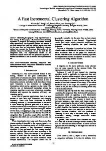
Fig. 6. Distribution of the solution times of the 474 OCC problems. The #-axis gives the number of problems solved within a certain time. The basic model is described in Section 4.1, clique uses clique inequalities to model interferences, cut extends the clique model by path cuts and clique-ray cuts, complete additionally includes reverse affinity cuts. Finally, hybrid combines Appel’s model with our cuts. Figure 6 shows the runtimes of different ILP models. The use of clique inequalities improves the performance very little (compared to basic), because CPLEX analyses dependencies between binary variables. Thus, the lack of clique inequalities in Appel’s model does not greatly matter, at least for mature solvers. Adding the cuts to the model (cut, complete) increases the performance significantly: The number of optimally solved problems rises from 243 to 430. Lowering the time limit to 6 seconds would still yield 300 solved problems, i.e., most problems can easily be solved using the cuts. Interestingly, for the easy problems our basic model performs better than Appel’s, but solves less problems in the end. Intuitively, one would expect better results when combining his model with our cuts, but the combination (hybrid) increases the overhead and degrades performance. Therefore, the performance of our best model must come from our tighter affinity encoding combined with the application of cuts. 4
This may be intractable for arbitrary graphs, i.e., with high affinity degree.
A Fast Cutting-Plane Algorithm for Optimal Coalescing
11
To complement the big picture with some numbers, Table 1 shows the solution times for the 309 problems optimally solved by both, Appel’s model and our complete model. Our method is approximately 15 times faster in these cases and could optimally solve 430 problems within time in contrast to the 311 solved by Appel’s. ILP Sum Average Max
Appel 20852.7 67.5 432.4
Complete 1332.3 4.3 195.1
Table 1. Solution times (in seconds) of the 309 OCC instances optimally solved by both ILPs within 450 seconds. Another indicator for the strength of our ILP is the solution quality produced within a given time limit. Table 2 lists properties of the best known solutions after 450 seconds of computing, including and excluding the optimally solved problems. The objective is minimized, so lower is better here. The gap absolute and gap relative rows show the distance between the best known solution and the optimal solution theoretically still possible. ILP Sum Gap abs Gap rel
Appel EO 126.7 126.1 99.5%
Complete EO 2.7 1.3 49.4%
Appel IO 128.1 127.4 99.4%
Complete IO 3.0 1.3 44.5%
Table 2. Solution quality (in millions of objective units) of feasible solutions after the time limit, excluding (EO) and including (IO) optimally solved problems. First of all, our method produced solutions being 50 times better. Second, the lower gap values indicate that our ILP produces tighter relaxations, which is useful to argue about solution quality. These advantages can be used if one is only interested in a solution provably lying in a certain distance to the optimum. However the tightness has one negligible drawback: There were 7 problems for which our ILP did not even yield a feasible solution in time. Although Appel’s approach did yield feasible solutions, this is negligible because these solutions were far from optimal. Informally speaking, our first integer solution might take some time longer to pop up but then is better than those produced by Appel’s ILP in the same time. Last but not least we dropped the time limit to compute all optimal solutions. These were used to determine the absolute quality of the following coalescing heuristics: Iterated Coalescing [3], Optimistic Coalescing [4], a heuristic by Hack [8] directly designed for the SSA case, and another result set by Fang, which was produced with a local search SAT solver and is published on [7]. Figure 7 illustrates the big picture and Table 3 gives the corresponding numbers. The best heuristics solve about 175 problems optimally. Most of the prob-
12
Daniel Grund, Sebastian Hack
lems can be solved with an objective function below 2 · OP T (100%). The graph shows, again, previous experience [4,15] that optimistic coalescing performs better than iterated coalescing. From the table, one can derive that optimistic coalescing has a good average-case behavior (34%), but some difficult problems raised the overall deviation to 53%. A tuned version (Optimistic II) behaves vice versa: 60% on average but only 44% in total. Our SSA heuristic is competitive and comparable to optimistic coalescing, but more balanced (46%, 51%). No heuristic yields solutions better than 44% (over all cases) above the optimal solution. This picture changes only little if one removes the outliers. # Optimistic I 474
Optimistic II SSA Heuristic
400
Local SAT
300 Iterated
200
100 10
20
30
40
50
60
70
80
90
100
110
% above OPT
Fig. 7. Distribution of the solution qualities for coalescing heuristics. The %-axis gives the quality in terms of the allowed deviation from an optimal solution. The #-axis gives the number of solutions within a certain quality. E.g., iterated coalescing produces 200 solutions such that each is not more than 40% above the respective optimal solution.
Algorithm Objective sum Difference to Opt % above Opt Average % above Opt
ILP Iterated Optimistic I Optimistic II SSA Heur Local SAT 26.3 66.4 40.4 37.8 38.4 38.9 0.1 40.0 14.0 11.5 12.1 12.6 0.4 152 53 44 46 48 0 219 34 60 51 60
Table 3. Comparison of different coalescing algorithms. The first two rows are given in millions of objective function units, the last was obtained by first calculating the percentage differences for all problems and then taking their arithmetic mean. (3 ILP solutions might not be optimal, but tight bounds can be given) Some last remarks on the OCC: Due to the live-range splitting after each instruction we could only generate 22 clique-ray cuts, all equivalent to a path cut of length two, compared to 135942 path cuts. For the same reason the data size reduction was not applicable at all to this test set.
A Fast Cutting-Plane Algorithm for Optimal Coalescing
5.2
13
SPEC CPU2000 benchmarks
To compensate the disadvantages of the OCC we performed a second benchmark, this time on a Pentium 4 2400. We compiled a subset of the SPEC CPU2000benchmarks [16] consisting of C programs using Firm [17] with its SSA-based x86 backend. In this setting, live-range splitting is limited to SSA construction, spilling5 and the handling of register constraints. Here, the data size reduction is applicable and worthwhile: The average number of removed nodes was 10%. Since live-range splitting is frequent for x86 (high number of constrained instructions), we assume that this percentage is even higher for standard RISC architectures. The number of generated cliqueray cuts was 227 and the number of path cuts was 112486. Prior to the ILP, we ran the SSA heuristic on the graph and provided its solution as a start value to the ILP solver. Hence, there always was at least a feasible solution. Out of 4459 problems, only 211 (4.7%) were not solved optimally within 5 minutes. In those cases we also recorded the best lower bound (BLB in the following) known to the solver after the time limit was reached. The optimal solution of a problem lies between the BLB and the objective value returned. However, a common observation in practice is that the solver lowers the objective value and then remains a long time at the same best solution, only raising the lower bound, i.e., proving optimality of that solution. Therefore, some of the 211 feasible solutions might be optimal but the solver failed to prove it within time. 164.gzip 175.vpr 176.gcc 181.mcf 186.crafty 197.parser 253.perlbmk 254.gap 255.vortex 256.bzip2 300.twolf
Max Costs 3456885 17105748 221483452 136390 27781660 22227033 49321969 131547137 28572683 7007580 162497955
5min 97356 218105 3429671 6925 852833 678415 1596567 2908392 1292513 239528 2915713
BLB 5min 30935 215758 2641368 4567 390419 609249 1424011 1930799 1248252 196840 1253567
%5min 2.82 1.28 1.55 5.08 3.07 3.05 3.24 2.21 4.52 3.42 1.79
%BLB 5min 0.89 1.26 1.19 3.35 1.41 2.74 2.89 1.47 4.37 2.81 0.77
Table 4. Results of the SPEC2000 benchmark Table 4 shows the results of the benchmark. The column “Max Costs” lists the maximal costs of the benchmark, “5min” shows the remaining costs after at most five minutes of optimization. “BLB 5min” shows the costs if the best lower bound is assumed as the optimal objective value for problems that could not be solved within five minutes. “%5min” and “%BLB 5min” show the respective percentages regarding “Max Costs”. The ILP formulation was able to compute optimal solutions in 95% of all cases and the other solutions were near-optimal. 5
All subranges between two references (def/use) can be spilled separately.
14
6
Daniel Grund, Sebastian Hack
Related Work
Goodwin and Wilken [18] were the first applying ILP to register allocation. They addressed the full problem of register allocation including spilling, rematerialization, callee/caller save register handling, register assignment and coalescing. Thus, they solved a much harder problem on older hardware with older ILP solver technology. The only optimization they performed, was to reduce the size of the ILP by restricting the spill and reload decisions to sensible program points. Fu and Wilken [19] improved this work by speeding up solution times. They identified several kinds of redundant or symmetric decisions and removed them from the ILP formulation. These optimizations together with faster hardware and better ILP solvers (7 years in between), resulted in significantly more functions being optimally allocated in less time. Between these two publications, Appel and George [15] proposed decomposing this problem into two subproblems: Spill code placement and register coalescing, of which the latter also includes the actual assignment. They solved both problems by ILP and empirically showed that decomposing the problem does not significantly worsen the overall allocation quality. One point is unique to their approach: They potentially allow splitting live ranges after each instruction. However, this may be one of the reasons why the authors called their coalescing ILP far too slow and left an efficient algorithm for optimal coalescing as an open problem [7]. Our setting compares best to Appel’s: We also separate spilling and coalescing, but for a better reason (chordality), and have basically the same starting point for coalescing, with the following differences: We do not allow live-range splitting after each instruction, although we are capable of solving such problems. Instead, our split points are limited to those introduced by SSA construction, spilling, and the handling of register constraints. Concerning the ILP, our formulation differs from Appel’s in the following points: We use a smaller and more efficient encoding of the affinity edges and efficiently generate clique inequalities to express the interference constraints. Admittedly, the clique inequalities contribute little to the performance because modern solvers have this optimization as a built-in function. Furthermore, all prior approaches focused on reducing the size of the ILP formulation. Additionally, we add supplementary cuts to cut down the search space, which is more sensible than a smaller formulation with a larger feasible region.
7
Conclusions and Further Work
Although this work began in a SSA context, the algorithm and all optimizations are applicable to the non-SSA case, as long as coalescing is separated from spilling. Our ILP model performs better than previous approaches: It needs significantly less time to compute optimal solutions or it can produce better solutions within a given time limit. If one should point out one crucial point it is the cutting planes. But to achieve top performance all the optimizations must go hand in hand.
A Fast Cutting-Plane Algorithm for Optimal Coalescing
15
For very large problems and extreme live-range splitting scalability comes to an end: The ILPs are so large (200000×200000 matrix) that solving the continuous relaxations consumes too much time. Future work could push this limit and investigate whether a benders decomposition or the new feature of CPLEX 10 to model implications are worthwhile. Other constraint solving techniques could be considered but 0/1-LP already is a very special problem class and ILP has the advantage to provide lower bounds. Another point that could be interesting for practical and theoretical reasons is the question which live-range splitting points are really necessary to achieve an optimally coalesced program.
References 1. Chaitin, G.J.: Register allocation & spilling via graph coloring. In: SIGPLAN symposium on Compiler construction, New York, NY, USA, ACM Press (1982) 2. Briggs, P., Cooper, K.D., Torczon, L.: Improvements to graph coloring register allocation. ACM Trans. Program. Lang. Syst. 16(3) (1994) 3. George, L., Appel, A.: Iterated Register Coalescing. ACM TOPLAS 18(3) (1996) 4. Park, J., Moon, S.M.: Optimistic Register Coalescing. ACM TOPLAS 26(4) (2004) 5. Hack, S., Grund, D., Goos, G.: Register Allocation for Programs in SSA-Form. In: Compiler Construction 2006. Volume 3923., Springer (2006) 6. Appel, A., George, L.: Optimal Spilling for CISC Machines with Few Registers. Technical report, Princeton University (2000) 7. Appel, A.: Optimal Coalescing Challenge. http://www.cs.princeton.edu/ ∼appel/coalesce (2000) 8. Hack, S.: Register Allocation for Programs in SSA-Form (to appear). PhD thesis, University of Karlsruhe (2006) 9. Schrijver, A.: Theory of Linear and Integer Programming. J. Wiley & Sons (1986) 10. Nemhauser, G., Wolsey, L.: Integer and Combinatorial Optimization. WileyInterscience New York (1988) 11. Hack, S., Grund, D., Goos, G.: Towards Register Allocation for Programs in SSAform. Technical report, University of Karlsruhe (2005) 12. Bir´ o, M., Hujter, M., Tuza, Z.: Precoloring extension. I. Interval graphs. Discrete Mathematics 100 (1992) 13. Garey, M.R., Johnson, D.S.: Computers and Intractability: A Guide to the Theory of NP-Completeness. W. H. Freeman (1979) ISBN: 0716710455. 14. Gavril, F.: Algorithms for Minimum Coloring, Maximum Clique, Minimum Covering by Cliques, and Independent Set of a Chordal Graph. SIAM Journal on Computing 1(2) (1972) 15. Appel, A., George, L.: Optimal Spilling for CISC Machines with Few Registers. In: ACM SIGPLAN Conference PLDI. (2001) 16. Standard Performance Evaluation Corp.: http://www.spec.org/cpu2000/ (2000) 17. Lindenmaier, G., Beck, M., Boesler, B., Geiß, R.: Firm, an Intermediate Language for Compiler Research. Technical Report 2005-8, University of Karlsruhe (2005) 18. Goodwin, D.W., Wilken, K.D.: Optimal and Near-optimal Global Register Allocations Using 0-1 Integer Programming. Softw. Pract. Exper. 26(8) (1996) 19. Fu, C., Wilken, K.: A Faster Optimal Register Allocator. In: Proceedings of the ACM/IEEE international symposium on Microarchitecture, Los Alamitos, CA, USA, IEEE Computer Society Press (2002)