Procc. of 10th International Conference on Information 10th International Conference on Information Technology Technology, December 17-20, 2007, Rourkela, pp. 38-40
A Fast Edge Detection Algorithm for Road Boundary Extraction Under Nonuniform Light Condition Aurobinda Routray Deptt. of Electrical Engineering, I.I.T. Kharagpur-721302, India
Kanungo Barada Mohanty Deptt. of Electrical Engineering, N.I.T., Rourkela-769008, India
[email protected],
[email protected]
Abstract
Only the lower half of the image needs to be used to predict the immediate future coordinates for guidance. In addition to that, this algorithm is insensitive to the unevenness and roughness in the roads, which manifest as regions of non-uniform intensity.
In this paper a fast edge detection algorithm based on a simple logic has been implemented for road boundary detection in non-uniform light condition. Road images taken in the campus have been used to test the algorithm. First the image samples are segregated into different segments depending on the intensity. Subsequently standard edge detectors are applied to extract the edges in each of the segments. A logical operation between the edges of the different segments brings out the edges of the final image.
2. The Algorithm
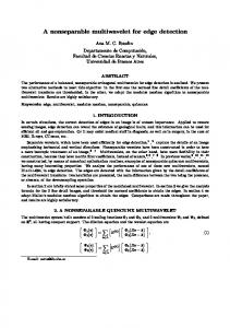
The block diagram representation of the algorithm is shown in Fig. 1. The actual image-data is processed through two independent steps and finally the combination of these two steps gives the output. Different stages of this algorithm are briefly explained below.
[email protected],
[email protected] [email protected], Road boundary detection is one
[email protected] the important Image
1. Introduction
guiding factors in autonomous and semi-autonomous vehicles. Simple edge detection algorithms that extract all the edges found in the area of interest as well as in the surroundings, are not quite efficient under nonuniform light and noisy measurement conditions, something unavoidable for on-board cameras. A single camera with Conic Projection Sensor System has been used in [1], while a two camera system has been used in [2] to get real-time images and the 3-D perspective is removed for vehicle guidance. In [3], Hough Transform has been used to extract 3-D road boundaries in the images coming from a stereo-vision system. Geometrical features are used in [4] to find road boundaries out of a set of many image segments. A multi order line segment description of the road boundary has been achieved through a statistical test, in [5]. The edge location and edge orientation are also considered in [5]. In [6], lowlevel structures are extracted via a non-linear transform and it proposes an algorithm for segmentation of images at multiple scales. A simple and fast method based on segmentation followed by edge detection and logical operation has been suggested in this paper for road-edge detection.
0-7695-3068-0/07 $25.00 © 2007 IEEE DOI 10.1109/ICIT.2007.9
High Intensity Scaling
Edge Dete ction
Noise Removal
Logic
Low Intensity Scaling
Edge Dete ction
Output
Fig.1 Block diagram representation of the algorithm
2.1 Image pre-processing Let the image be represented as, I ( x, y ) , with x and y being the two coordinate directions. Median filtering, proposed in [7], is used for noise elimination. Fig. 2(a) is the original image of road while Fig. 2(b) is the median filtered image. Median filter can be represented as, v(m, n) = median { I ( m - k, n - l ), ( k, l ) ∈ W } Where, W is a suitably chosen window. The intensity scaling is implemented to eliminate the effect of variation in light as well as, the influence
38
of the background. Scaling is done taking the selected value of upper and lower threshold as the reference. The value of upper and lower threshold varies between ‘0’ and ‘255’, respectively the smallest and largest gray scale intensity values of any image pixel. Scaling has the form, 1. I min if i(x, y) < = a i(x, y) a , b = 2. i(x, y) × I max / (b - a) if a < i(x, y) < b
minimized in the region within the road boundaries. The same happens with the region outside the road boundary when we scale out high intensity values, only difference being that this time the region with intensity greater than the upper threshold becomes white. This happens due to the road being darker than the surroundings (this assumption is made because this is the most likely condition to be faced by the vehicle during its course of motion). This method also takes care of the case where the road is lighter in intensity than the surrounding because of the opposite effect. Thereafter, logical AND operation of the two output image data gives us the required edge as the region near the road boundaries is most likely the only common region in the two images and hence the edges in other regions get discarded as AND operation can take only simultaneously high pixel values in both the images.
3. I max if i(x, y) >= b Where, Imax = maximum possible value of intensity Imin = minimum possible value of intensity i(x, y) = actual value of intensity at a point (x, y) a = lower threshold for intensity scaling b = upper threshold for intensity scaling Also, 0