Most noticeable ones include Clos networks and Benes networks. Permutation networks are widely used as switching matrices in network routers and switches.
A Fast Parallel Routing Algorithm for Benes Group Switches Enyue Lu and S. Q. Zheng Department of Computer Science University of Texas at Dallas Richardson, TX 75083-0688, USA enyue, sizheng � @utdallas.edu ABSTRACT A parallel routing algorithm for controlling the class of interconnection networks called group connectors is presented. Given any legal mapping from input to output groups with busy inputs, this algorithm can determine the switch setting of a Benes group connector with inputs and output groups in time on a completely connected computer or the EREW PRAM model with processing elements. The implementations of this algorithm on various realistic parallel machine models are also discussed.
�������
��� �� ����������� ��� ��
KEY WORDS Group Connector, Rearrangeable Nonblocking Interconnection Network, Parallel Algorithm, Dense Wavelength-Division Multiplexing (DWDM), Network Switch, Network Router.
1
� �� !" #�
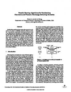
were proposed in [18], and it was shown that a group connector can be built at a lower hardware cost than that of a permutation network of the same size. For example, an Benes network, denoted by , is a rearrangeable nonblocking permutation network with SEs, and a rearrangeable nonblocking based on can be built with SEs. The saving in SEs by using is . (In this paper, all logarithms are .) in base 2 and all SEs are in size of In general, a group connector captures the simultaneous connections between clients and servers which are servers divided into equal-size server groups such that the in each group are functionally equivalent. A group connector can also be viewed as an permutation network with internal speedup of factor achieved by space-division multiplexing [17].
D%�� �� � �� ��� %K $�%)�$���) EF0 ��� )&�� ��� @GIDLHJ� �� �� $�)��MEN��)&�� ��� OG64 H�G 4 � � �� !�� % " %$�)�0�� �� A$�)��#E )L� �-) �� !P #�
%$�
� �� !" #�
Q�B
%$�
Introduction
���
1
.. .
Ch 1,1 Ch 1,2 Ch 1,N/n
OLC
2
.. .
Ch 2,1 Ch 2,2 Ch 2,N/n
n
.. .
Ch n,1 Ch n,2 Ch n,N/n
%$�
�� %$� &�
('*),+�" -'*)�+/.10 293 � 3 � �' 2
��� �� ��>�9� ���R �
b\V
b+ b + V`
� V V V Y V Y . GBH R ' 2 �O . � R>'C�@G*H
�
�
with length no more than vertex of � at most once.
)��
since each cycle or path visits every
�
Step 2: find the representative for every busy input. By the proof of Theorem 1, we know graph model � is 2-coloring. We choose a representative for the edges with the same color on every cycle or path. Thus, each cycle or path has two different representatives, and each represents the edges with the same color in this cycle or path. For a cycle, we choose each representative be the busy input with smallest label among all inputs with same color in the cycle. It is clear that two representatives of a cycle must be a pair of sibling inputs. For a path, If the end input is the busy input of a semi-busy SE, it is chose as a representative of the path; otherwise the input adjacent to this end input is chose as a representative of the path. Thus, for an even path, if the end inputs are in semi-busy input SEs, we choose two representatives be those two end inputs, and otherwise we choose two inputs adjacent to end inputs. For an odd path with length , only one of two end inputs of the path is in a semi-busy input SE, and this end input is chosen as one representative, called primary representative of the odd path. And another representative, called non-primary representative, is chosen be the input adjacent to another end input in a busy SE. For a path with length , two representatives are same, corresponding to the only one input of the path, and this one representative is also called primary representative. The representative of busy input , denoted by , is one of the representatives of the cycle or path in which inputs and are so that they are colored with same color. Every busy input will find its representative by pointer jumping[5]. If the sibling of input is idle or the input has no dual input, we know that the busy input is the end input of a path. For every non-end busy input, if the dual input of its sibling input is busy, the pointer is initialized to point to it; otherwise it points to itself. Since the length of a cycle or a path is at most , for each busy input, times of pointer jumping are enough to get the information what its representative is and if it is in a path or cycle.
8H
H
R
bJV
7 ��R �
�
7 ��R �
�� ����
Step 3: set all busy inputs by their colors. Two different representatives of a cycle or a path are colored with two different colors. Since two representatives of a cycle are sibling inputs, we can color every busy input in a cycle by the parity of its representative. In an odd path, the number of edges with the color of the primary representative is one more than the number of edges with color of the non-primary representative. In order to connect no more than half busy inputs with the same subnetwork of next level, we color all representatives first so that the difference of number of primary representatives with different colors is at most . Then, we color all busy inputs according to their representatives. Before coloring the representatives, each busy input needs to find another representative of cycle or path in which it is. If neither of the sibling or dual input of a busy input is busy, this busy input is in a path with length . In this case, two representatives are same. Otherwise, the busy input can find another representative by its sibling input or dual input. If two representatives are identical or they are in two SEs with different types, i.e. one in a busy SE and another in a semi-busy SE, this busy input knows it is in an odd path and in an even path otherwise. For all busy inputs in odd paths, we mark those inputs with labels same as primary representatives and perform parallel prefix sum to give each of them a unique rank. In order to set the input with minimum label of each subnetworks straight, we check if it is among those marked inputs. If yes, we color all marked inputs with same parity as it’s as red, and others as blue. Otherwise, all marked inputs(i.e. primary representatives) with different parity of rank
H
' H
gets different colors. The non-primary representative can be colored with different color as the corresponding primary representative. Similarly, all representatives of even paths can be colored, as we can mark all busy inputs with the smaller one between two representatives and perform parallel prefix sum on them. Finally, color remaining busy inputs as the same colors as their representatives. We set the busy input with even label and red color or that with odd label and blue color as straight, and as cross otherwise. It is easy to see that the difference of number of busy inputs connected to different subnetworks of next level is at most . Thus the number of busy inputs connected to the same subnetwork of next level is reduced by half after each iteration. Step 4: reassign mapping � for each input in next stage. After finishing setting of all inputs in the stage � , the input of ) ) ) !� � the stage � is connected to one of inputs � mod according to � � � � � of stage � the setting of input , i.e. if is even and is set straight or is odd ) and is set cross, input of stage � is connected to input of stage ) � , otherwise input of stage � is connected input � of stage � . Thus each � � gets the values of � for setting of busy input of next stage in the next iteration. Our algorithm in PHASE II is presented in such a way that all PEs participate routing process for P2 of . Actually, once the setting of SEs in P1 is determined, cells can be injected into . When the cells reach P2, the SEs can determine its setting by inspecting the control bits of SEs. We need time to find the number of busy inputs by performing prefix sums. Since the length of cycle or path is at most , we need time to perform pointer jumping, prefix sums and sorting in first iterations. Because the number of busy inputs connecting to the same subnetwork of next level is reduced by half after each iteration, each iteration in PHASE I only takes time after iterations. Thus, the total time for PHASE I is . There are iterations in PHASE II, each takes time. Therefore, the total time complexity of algorithm ROUTE is . In summary, we have the following claim:
H
��R �
R R � %$�) Y U� ' �� R 9 �QH R �9 %$�) Y ��R �
%$�) �P$�)d�9 %$�) E XR $N�� %$�) � ]� R R R � H R � H /V R
� �� !" #�
� �� !" #�
��� �� ��� �� ��� �� ����9�
�
���PHJ�
�� ����
��� �� ����9� ��� �� �� ���5���� �� �� ���PHJ�
) �� �� G 4 ��� �� �� ���5� �� ��� �� �
Theorem 3 For any legal I/G mapping � , algorithm ROUTE correctly computes a feasible configuration of in time on a parallel completely connected computer or the EREW PRAM model using PEs.
��� �� ������B���� �� ��
� �� !" #�
Example 1 Figure 4 and the following discussion(in this example, if some value of an input does not exist, it is set as -1) show main idea of parallel algorithm ROUTE to set up busy inputs in &� the first stage of for a legal I/G mapping
�
� P� H F � R�� 2 H ) $ ��2