The International Archives of the Photogrammetry, Remote Sensing and Spatial Information Sciences, Volume XL-3, 2014 ISPRS Technical Commission III Symposium, 5 – 7 September 2014, Zurich, Switzerland
A FAST RECOGNITION ALGORITHM FOR DETECTION OF FOREIGN 3D OBJECTS ON A RUNWAY
!! ! ! !!
V. V. Kniaz a * a
State Res. Institute of Aviation Systems (GosNIIAS), 125319, 7, Victorenko str., Moscow, Russia -
[email protected] Commission III, WG III/3
!! !
KEY WORDS: 3D object recognition, foreign object detection systems, runway detection system ABSTRACT: The systems for detection of foreign objects on a runway during the landing of an aircraft are highly demanded. Such systems could be installed in the airport or could be mounted on the board of an aircraft. This work is focused on a fast foreign object recognition algorithm for an onboard foreign object detection system. The algorithm is based on 3D object minimal boundary extraction. The boundary is estimated through an iterative process of minimization of a difference between a pair of orthophotos. During the landing an onboard camera produces a sequence of images from which a number of stereo pair could be extracted. For each frame the runway lines are automatically detected and the external orientation of the camera relative to the runway is estimated. Using external orientation parameters the runway region is projected on an orthophoto to the runway plane. The difference of orthophotos shows the objects that doesn't coincide with the runway plane. After that the position of the foreign object relative to the runway plane and its minimal 3D boundary could be calculated. The minimal 3D boundary for each object is estimated by projection of a runway region on a modified model of the runway. The extracted boundary is used for an automatic recognition of a foreign object from the predefined bank of 3D models.
!! !
1. INTRODUCTION
1.1. Foreign object debris detection problem The state and the quality of a runway plays the critical role for the safety of the aircraft during the landing stage. Any foreign object on a runway poses a significant threat to the safety of air travel. Such an object usually called foreign object debris (FOD) has the potential to damage aircraft during critical phases of flight, which can lead to catastrophic loss of life and airframe, and increased maintenance and operating costs (FAA, 2009). It is estimated that damage caused by FOD costs the international aviation industry US$13 billion per year. Examples of FOD include:
! • • • • •
!
airport operation vehicles fueling tracks aircraft parts rocks, broken pavement garbage, maintenance tools
usually provide a great accuracy and capable to detect FOD as little as 3.0 cm high. However the usage of statically mounted FOD detection system could only provide the safety during the landing on runways equipped with such systems.
!
This paper presents the algorithm for detection of FOD using the mobile system mounted on top of an aircraft. Such system is capable to detect moderate size FOD on runways unequipped with stationary FOD detection systems. The algorithm uses the data from an electro-optical sensor to automatically detect the foreign object on a runway and estimate its position and size. If the object exists in the predefined database of possible FOD it is automatically recognized.
!
2. SYSTEM CONFIGURATION
2.1. Sensors and recognition process workflow
The foreign object detection systems are highly demanded by airports. Such a system consist of sensors that check the surface of a runway for any changes or unexpected objects. In the case of detection the system alerts the airport service.
!
1.2. Existing FOD detection systems Even prior to the development of any automatic FOD detection systems runways were constantly inspected by airport personnel. However the usage of automatic electronic FOD detection systems greatly increases FOD detection rate and reduces the potential hazard. FOD detection systems could be divided into two categories depending on the type of sensor they use. Nowadays systems with radar and electro-optical sensors are available. Such systems could be either stationary located on the ground or mounted on top of a moving inspecting vehicle. Such systems
To alert the pilot in the case of FOD on a runway it is proposed to mount an electro-optical sensor on top of an aircraft. An infrared sensor could be used to increase the performance of the system in the poor weather conditions.
!
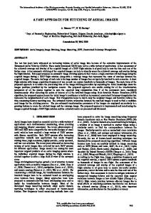
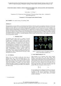
It is possible to use sensors incorporated in commercially available enhanced vision systems (EVS) to obtain the input data from for the algorithm. An example of EVS system with an infrared data sensor (1-5 Micron) manufactured by Kollsman presented on figure 1.
! !
The data from the sensor is transferred to the main processing unit. The recognition of FOD is done in the following steps: 1. 2. 3. 4. 5. 6.
Restoration of the original data. Detection of the runway. Determination of camera external orientation. FOD region estimation. Reconstruction of FOD 3D shape. Search for a similar object in the FOD database.
This contribution has been peer-reviewed. doi:10.5194/isprsarchives-XL-3-151-2014
151
The International Archives of the Photogrammetry, Remote Sensing and Spatial Information Sciences, Volume XL-3, 2014 ISPRS Technical Commission III Symposium, 5 – 7 September 2014, Zurich, Switzerland
!
Result of the convolution is shown on figure 3.
! !
! Figure 1. Infrared data sensor in EVS system. Credit: Kollsman
!
Figure 3. Image of the runway after convolution with the left border marking detection kernel
!
3. RUNWAY RECOGNITION
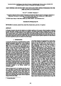
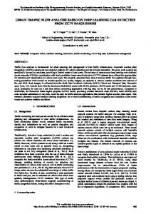
The essential step prior to the estimation of the external camera orientation is determination of reference points and lines on a runway. It is possible to use any visible feature points with known geodetic coordinates as reference points. The most persistent and noticeable features visible during the approach and the landing stages are runway edge markings during the day and runway edge lightning during the night. An example of typical runway edge marking is shown on figure 2.
After the convolution with both kernels two resulting images are binarization using Otsu’s method. To detect runway edge markings, threshold marking and touchdown zone marking an image segmentation was used.
!
!
An original fast image segmentation algorithm was developed to perform an image segmentation in real time. The algorithm performs the segmentation through the single scan of the image data. To detect image regions that has complex connections a label image is created during the scan. Each pixel of the label image holds the unique index of a separated area in the original image. Such index is assigned to each non-zero pixel of an original image that yet has no associated index in the label image. After that four neighbor pixels are examined (three in the vertical positive direction of the scan and one in the horizontal positive direction of the scan). The same index is assigned to each neighbor pixel if it is non-zero and doesn’t have any index in the label image yet. If the neighbor pixel already has an index in the label image the back substitution of indexes in the label image is done: all pixels with the current index of the current pixel are reindexed to the index of the neighbor pixel. The label image produced after the segmentation is shown on the figure 4.
! ! !
Figure 2. An example of typical runway markings in Domodedovo airport (DME). Credit: Google Earth.
Four reference points were chosen to develop a fast algorithm for runway recognition. They coincident with the beginning and the end of left and right edge markings of the runway.
!
3.1. Runway edge detection To detect edge markings of the runway a convolution with a vertical edge detection kernel is used. Usually the edge between runway marking and the inner part of the runway is more prominent than the edge between runway marking and the outer part of runway. To effectively detect runway edge marking in such cases left and right runway edge markings are detected separately by two different kernels given by:
!
! !
(1)
! !
Figure 4. Label image that shows the separated pixel region image of binary image. The runway left edge marking is visible as a long inclined blue line left to the image center.
! !
The automatic detection of runway edge markings is done under the following assumptions:
This contribution has been peer-reviewed. doi:10.5194/isprsarchives-XL-3-151-2014
152
The International Archives of the Photogrammetry, Remote Sensing and Spatial Information Sciences, Volume XL-3, 2014 ISPRS Technical Commission III Symposium, 5 – 7 September 2014, Zurich, Switzerland
• the length of a runway edge marking region is at least 1/10 of the image height • the borders of the region are parallel to its axis of symmetry (i.e. it is nearly a straight line) • the left runway edge marking has a positive gradient (i.e. is inclined towards the right border of the image) and the right edge marking has a negative gradient
4. CAMERA EXTERNAL ORIENTATION
!
The process of camera external orientation is done in two steps: firstly the rotation matrix is found using the vanishing points given by runway edge markings and the Gaussian sphere method proposed by (Barnard, 1983). Secondly the position of the center of projection is found using the runway reference points found on the image.
!
Given the following assumptions each region that was found in the original image is examined. Firstly all regions that have less pixels than 1/10 of the image height are excluded from the search. After that the straight line approximation of all remaining regions is performed. The approximation is done by a straight light fitting proposed by (Press, 2007).
4.1. Runway, camera and image coordinate systems
!
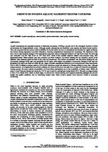
The runway coordinate system is defined as follows: the origin is located at the beginning of the right runway edge marking, Xaxis is coincide with the right runway edge marking, Y-axis is coincide with the line passing through the beginnings of edge markings, Z-axis is normal to X- and Y- axes. The image coordinate system is defined as follows: the origin is located at the bottom left pixel, X-axis is directed to the right, Y-axis is directed upwards. The camera coordinate systems is defined as follows: the origin is located at the projection center, X-axis is parallel to the image X-axis and has the same direction, Y-axis is parallel to the image Y-axis but has the opposite direction, Zaxis is normal to X- and Y- axes. Figure 6 illustrates runway, camera and image coordinate systems.
After the line fitting the borders of each region are checked to be parallel with the approximated axis of symmetry. Orthogonal distances to edges of the region are calculated (border profiles). The standard deviation of distances to edges gives the nonlinearity criteria. Regions with low standard deviations are likely to be lines.
!
Finally runway edge marking regions are selected using the nonlinearity criteria and approximated gradient of the line. The region with low nonlinearity and positive gradient on the left image is selected as the left runway edge marking. The right runway edge marking is found in the similar way.
!
!
3.2. Runway threshold and touchdown zone detection To detect runway threshold and touchdown zone markings the region between estimated border markings is searched. The line passing through the beginning of left and right border markings gives the position of the first scan lines. The label image (either left or right) is scanned along the lines that are parallel to the first scan line. If 12 (sometimes 16) regions with different indexes are found along the scan line they are chosen as runway threshold marking regions. If 6 regions with different indexes are found along the scan line they are chosen as runway touchdown marking regions. Figure 5 illustrates the process of runway threshold and touchdown zone markings detection.
! !
!
Figure 6. Runway, camera and image coordinate systems
!
4.2. Determination of rotation matrix The rotation matrix that defines the transformation from the camera coordinate system to the runway coordinate system is found using vanishing points. The vanishing point that is given by the intersection of runway border markings provides the direction of runway coordinate system X-axis in the camera coordinate system. To find the direction of runway coordinate system Y-axis runway threshold and touchdown zone markings are used. Two lines parallel to Y-axis of runway coordinate system could be defined as the line congaing front points of runway threshold and touchdown zone markings. The intersection of this lines gives the second vanishing point. The second vanishing point gives the direction of the runway coordinate system Y-axis in the camera coordinate system. The direction of Z-axis could be found as a cross product of vectors defining X- and Y- axes.
! ! !
The reference points on the runway are named as follows:
!
Figure 5. Process of runway threshold and touchdown zone markings detection
• bL, bR – beginning points of left and right runway edge markings • eL, eR – end points of left and right runway edge markings • tr(i) – 12 front points of threshold marking • td(i) – 6 front points of the first touchdown zone marking
!
This contribution has been peer-reviewed. doi:10.5194/isprsarchives-XL-3-151-2014
153
R=
x = xi $b C p0
The International Archives of the Photogrammetry, Remote Sensing and Spatial Information Sciences, Volume XL-3, 2014
xR==xi
ISPRS Technical Commission III Symposium, 5 – 7 September 2014, Zurich, Switzerland
T vX Coordinate points in the camera coordinate systems are named T with lowercase letters, R = e.g.vYbL. Coordinate points in the runway coordinate system are named with capital letters, e.g. BL. Coordinate points in the image coordinate system are named T with lowercase letters Tvwith T subscript, e.g. biL. The Z T ‘i’ R = thevXimage , vTY, vTcoordinate ; transformation from Z, vT ; system to camera = vby: , v coordinate systems isRgiven X Y Z
! !
!
x = xi b C p0
e C # bp ; n = e # b xn= x= $b
L i L L0 R R R 5. FOREIGN OBJECT DETECTION
(1)
To detect foreign x objects = xi $bonCthep0runway the orthophoto images difference method nL proposed = eL # bbyL;(Zheltov, n = e2000) # bisRused. As the images in the sequence captured Rby anR aircraft during the approach stage have different external orientation it is possible ndetect # nLobject that doesn’t lie in the to use a pair of images R b ;ann nvL == etoL # = e # bR L such R an Robject an T runway plane (figure detect orthophoto X 7). To v n # n T is generated to the runwayX play R L for each image and the (2) v X difference of orthophoto images is calculated. Any non-zero T nR #indicates nL a potential foreign object pixel R on = the difference vY T image vXv= located onRthe = runway. Y n #n T nRR # nLL v 5.1. Orthophoto T Z vgeneration vX Z= RK1 BL K BR n # n To generate the XC orthophoto to the runway plane a grid of the = R$b R r $L points in the runway 0plane is defined. Eachbpoint to K corresponds bR L each the pixel of the resulting orthophoto. For point an x = xi bwith C pthe0 image plane isKfound. intersection R 1 B The K Bintersection x = x bC p0 R The line point is found ias the intersection of a line andL a plane. XC0 = XC0 = R$br $ is given by: b K b K1 R LBL KRBR nL = eL bL C i0$ nL =! XC epL=b0Ld$i = R$b r (7) = bL K bR XC bpoint wherenpR–=isethe of intersection, d – is the distance along0 R R nR =vector eR biRfrom i0, i – direction vector of the line the direction given by the vector of the point on the runway inXC the = p = d$i Ccurrent i camera coordinate system, i0 –0 is a point on the line (projection0 center). The plane is given by:
(2)
!
where x - point in the camera coordinate system, xi - point in the image coordinate system, b - pixel scale, p0 – principal point position in the camera coordinate system.
!
Using this notation planes containing x =normals xi $b Cto pinterpretation left and right border xmarkings = xi $b inC0thep0image plane in the camera coordinate systems are given by:
! !
nL = eL # bL; nR = eR # bR nL = eL # bL; nR = eR # bR !
!
(3)
The unit vector vX that gives the direction of X-axis of the runway coordinate system in the camera coordinate system is given by:
!
vX =
!
!
nR # nL nR # nL
! !
(4)
The second vanishing point is found in the similar way using points tr(1), tr(12), td(1), td(6) located on runway threshold and and touchdown zone markings lines. This vanishing point provides the unit vector vY that gives the direction of Y-axis of the runway coordinate system in the camera coordinate system. The unit vector vZ that gives the direction of X-axis of the runway R coordinate = vTX, vTYsystem , vTZ ; in the camera coordinate system is given as cross product of vX and vY.
!
After that the rotation matrix that defines the transformation from the camera coordinate system to the runway coordinate system is given by: R=
!
!
p = d$i C i0 p Kp0 $n = 0
where p – is the point p Kofp intersection, $n = 0 p0 – is a point on a plane (principal point position),0n – is normal to the plane. Solving (7) and (8) for d gives the distance from i0 to the point of intersection p:
!
vTX
d= !
p0 Ki0 $n i$n
(9)
Substituting d back to (7) gives the point of intersection in the
vTY camera coordinates system. Using the equation (2) the (1) pixel coordinates in the image coordinate system are found. The value
vTZ of that pixel gives the value of the current point on the
vTX
orthophoto. An example of resulting orthophoto is shown on figure 8, a.
!
x = xi $b C p0 T
R=
vY
(1)
x = xi b C p0
(2)
nL = eL # bL; nvRT= eR # bR
!
!
Z
n(5) = eL bL L
4.3. Determination of the projection center
nR = eR bR
(3)
The vector bR coincide nR # nLwith the center of origin of the runway coordinate The rotation of this vector by R matrix gives vX system. = the direction vector nR # ntoL the center of origin of the camera coordinate system in the runway coordinate system. To find the length of this vector the scale is found using the runwaynR nL vX = reference points. Two reference points BL and BR that represent nR nL the width of the runway are used:
!!
(8)
!
XC0 = R$br $
(4)
RK1 BL K BR bL K bR
(6)
! Figure 7. A pair of images used for the detection of foreign objects obtained by onboard camera during the landing
This contribution has been peer-reviewed. doi:10.5194/isprsarchives-XL-3-151-2014
154
x =nLxi=
n = x =Rxi nL =
nR = nL =
vnXR== vX = vX =
R BL K
R BL K
R BL K p=d
p=d
pKp
The International Archives of the Photogrammetry, Remote Sensing and Spatial Information Sciences, Volume XL-3, 2014 ISPRS Technical Commission III Symposium, 5 – 7 September 2014, Zurich, Switzerland
T
T
T
R = vX, vY, vZ ; T
vX R=
T
vY
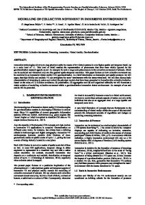
Figure 8. (a, upper) An example of an orthophoto with a foreign object (a firetruck) visible on the right side. (b, middle) Second orthophoto generated from the image captured fromTthe different position of the camera. vZ (c, down) Difference of orthophotos.
x = detection xi $b C p0 5.2. Foreign object x = xi b C p0
To detect a foreign object a pair of orthophotos is generated. The non-zero pixels of the difference of orthophotos indicate the nL =thateLdoesn’t # bL;lienRin =theeRrunway # bRplane (i.e. an location of an object object with non-zero height). An example of the difference of orthophotos is shown on figure 8, c. The foreign object is clearly visible as the bright spot on the left side of the difference image.
nL = eL bL
!!
nR = eR bR
6. FOREIGN OBJECT RECOGNITION nR # nL v = To automatically Xfind the detected object in the predefined # nL bounding box is estimated database of 3D objects n aR minimal using the orthophoto. After that an object with the most similar dimensions of the minimal bounding box is searched in the database. The 3D object with a closest minimal box dimensions found in the database gives the type of the detected object. !
vX =
!
K1 6.1. Foreign object position and Rminimal bounding BL K BR box estimation XC = R$b $ 0 r bL K bR To estimate the position and the minimal bounding box of the foreign object binarization and image segmentation of the orthophoto is done. The bright region in the difference of the XC orthophotos gives the seed point for image segmentation in the0 orthophoto. An example of binarization of the orthophoto is shown on figure 9. The difference of the orthophotos image is p = d$i C i0 to exclude the bright region then added to the binary image from the foreign object region. After the segmentation an approximation of the contour of the foreign object region with a rectangle is done. The contour of the bright region visible on the Kpapproximated $n = 0 with a rectangle. difference image ispalso 0
!
!
!
h=
2
l Kd2
(10)
where h – is the height, l – diagonal (width of foreign object rectangle), d – depth (width of bright region rectangle)
nR nL
R br
=
R BL K BR
bL K bR
p = d i C i0
!
After that the parameters of the minimal bounding box are found. The height of the foreign object rectangle gives the p0 Kibounding $n box in the runway actual width of the minimal 0 coordinate space.dThe = width of the bright region rectangle gives the depth of the minimal i$n bounding box. The width of the foreign object rectangle actually represents the diagonal of the minimal bounding box in the height/depth plane. So the actual height of the foreign object is given by:
nR nL
p K p0 n = 0 !
!
Figure 9. (a, upper) Fragment of the original orthophoto centered on the foreign object. (b, lower) Binarization of the orthophoto. Bright region visible on the difference of is shown with red. p0 Korthophotos i0
d=
!
The position of i the foreign object in the runway coordinate system is also found using the orthophoto. The bottom left point of the foreign object rectangle defines the origin point of the foreign object coordinate system. The rotation of the main axes of the foreign object rectangle gives the rotation of the foreign object coordinate system around the Z-axis.
This contribution has been peer-reviewed. doi:10.5194/isprsarchives-XL-3-151-2014
155
The International Archives of the Photogrammetry, Remote Sensing and Spatial Information Sciences, Volume XL-3, 2014 ISPRS Technical Commission III Symposium, 5 – 7 September 2014, Zurich, Switzerland
6.2. Minimal bounding box dimensions refinement To refine dimensions of the bounding box an iterative minimization of the difference of orthophotos is done. After the primary estimation of minimal bounding box position and dimensions it is appended to the runway 3D model. Runway points located under the minimal bounding box a lifted to the height of the minimal bounding box. Using the new runway 3D model a new pair of orthophoto images is generated. To get the new pixel values of the orthophoto each ray connecting the runway point and the image plane is checked for intersections with planes of the foreign object minimal bounding box.
of the landing, especially in airports that are not equipped with stationary FOD systems.
!
If the ray intersects a plane of the minimal bounding box the current runway point is invisible from the camera point of view. Such point is labeled with zero value on the resulting orthophoto (black color). A new pair of orthophotos generated using the updated 3D model of runway is shown on figure 10.
!
! !
Figure 11. The resulting difference of orthophotos images after the process of iterative minimization.
!
An algorithm for fast detection and recognition of foreign objects on a runway was developed. The algorithm automatically detects runway markings and estimates the camera external orientation in the runway coordinate system. The algorithm doesn’t require navigation information of an aircraft for estimation of the external orientation. The only additional information needed is the geodetic coordinates of reference points on the runway. The algorithm detects and estimates the dimension of the foreign object using the difference of the orthophotos. !
!
The test input data for the algorithm was created using a 3D modeling software. A 3D model of the airport scene was created and images from a virtual camera were rendered. Errors in the estimation of the external parameters were no more than 5 meters in the runway space. !
Figure 10. New pair of the orthophotos generated using the updated 3D model of the runway. The black areas represent the regions of the runway that are invisible from the camera’s point of view (i.e. occluded by the foreign object). Note that the pixels representing the roof of the firetruck are now located on the place where the firetruck is positioned.
!
After the generation of the new pair of orthophotos their difference is found. If the primary estimation of the parameters was good enough values of the difference image should be close to zero (i.e. black image should be produced). If the were errors in the estimated dimensions of the minimal bounding box the iterative minimization of the difference of orthophotos is done. Small increments are given to the width, the height and the depth of the minimal bounding box and a new pair of orthophotos and their difference image are generated. The integral value of the new difference image is compared with the integral value of the previous image. If the new integral value is smaller than the previous one a new increment to the dimensions is done. The process continues until the desired minimal integral value is reached (figure 11).
!!
7. CONCLUSIONS A combination of a basic EVS system and the algorithm that uses image processing and photogrammetric methods provides a way to detect moderate size foreign objects located on a runway. The usage of such algorithm could increase the safety
To reduce the errors it is suggested to use all available runway reference points during the process of projection center position estimation. The major step to improve the quality of object recognition can be done by presenting a 3D model of a foreign object in voxel form with variable voxel size. The recognition of such features could be done by a recursive application of the developed algorithm. REFERENCES Barnard, S. T., 1983. Interpreting perspective images. Artificial Intelligence 21, pp. 435-462.
!
Press, W.H., Teukolsky, S.A., Vetterling, W.T., and Flannery, B.P., 2007. Numerical Recipes: The Art of Scientific Computing, Third Edition, 1235 pp. (New York: Cambridge University Press). U.S. Federal Aviation Administration, 2009. Advisory circular on Airport Foreign Object Debris (FOD) Detection Equipment (30 Sep. 2009). Zheltov S., Sibryakov A., 2000. Method of 3d-object detection based on orthophoto difference analysis. The International Archives of Photogrammetry and Remote Sensing. Vol. XXXIII, Part B3. Amsterdam.
This contribution has been peer-reviewed. doi:10.5194/isprsarchives-XL-3-151-2014
156