various numbers of elements. The governing differential equation is that pre-described by the Bernoulli beam which is a fourth order differential equation.
International Journal of Applied Science and Technology
Vol. 2 No. 8; October 2012
A Finite Element Solution of the Beam Equation via MATLAB S Rao. Gunakala Department of Mathematics and Statistics The University of the West Indies St. Augustine. Trinidad and Tobago D.M.G. Comissiong Department of Mathematics and Statistics The University of the West Indies St. Augustine. Trinidad and Tobago K.Jordan Department of Mathematics and Statistics The University of the West Indies St. Augustine. Trinidad and Tobago Alana Sankar Department of Mathematics and Statistics The University of the West Indies St. Augustine. Trinidad and Tobago
Abstract The vertical deflection of a simply supported and clamped beam is considered under a uniform load using the finite element method. The problem is solved using homogenous and non-homogenous boundary conditions with various numbers of elements. The governing differential equation is that pre-described by the Bernoulli beam which is a fourth order differential equation. Cubic elements are used as required for continuity. Graphs are presented and discussed for different loads in each case.
Keywords: Finite element method, Beam equation, Homogenous and non-homogenous conditions 1. Introduction Beam equations have historical importance, as they have been the focus of attention for prominent scientists such as Leonardo da Vinci (14th Century) and Daniel Bernoulli (18thCentury). Practical applications of the beam equations are evident in mechanical structures built under the premise of beam theory. The importance of beam theory has been outlined in the literature over the years(see for example [3], [4], [5]). Examples include the construction of high-rise buildings, bridges across the rivers, air craft and heavy motor vehicles. In these structures, beams are used as the basis of supporting structures or as the main-frame foundation inaxles. Without a proper knowledge of beam theory, the successful manufacture of such structures would be unfeasible and unsafe. The Euler-Bernoulli beam theory, sometimes called the classical beam theory, is the most commonly used. It is simple and provides reasonable engineering approximations for many problems.In the paper, we shall illustrate the use of the Galerkin Finite Element Method to solve the beam equation with aid of Matlab. The Finite Element Method (FEM) is one of the most powerful tools used in structural analysis. Finite Element Analysis is based on the premise that an approximate solution to any complex engineering problem can be reached by subdividing a larger complex structure into smaller non-overlapping components of simple geometry called finite elementsor elements.Complex partial differential equations that describe these structures can be reduced to a set of linear equations that can easily be solved using this method. 80
© Centre for Promoting Ideas, USA
www.ijastnet.com
Elements are interconnected by points called nodes. Nodes will have nodal (vector) displacements or degrees of freedom which may include translations, rotations, and for special applications, higher order derivatives of displacements. In the Galerkin finite element method a trial function is substituted into the governing equations and the unknown node values are determined.
2. Governing Equation In the Euler-Bernoulli beam theory, the transverse deflection 𝑢 of the beam is governed by the fourth order differential equation 𝑑2
𝑑2𝑢
𝑟 𝑥 𝑑𝑥 2 = 𝑓 𝑥, 𝑢 , 0 ≤ 𝑥 ≤ 𝐿 subject to the free end boundary conditions 𝑑2 𝑢 0 𝑢 0 = 𝑎0 , = 𝑏0 , 𝑑𝑥 2 𝑑2𝑢 𝐿 𝑢 𝐿 = 𝑎𝐿 , 2 = 𝑏𝐿 . 𝑑𝑥 2
𝑑𝑥
(1)
(2)
The function 𝑟 𝑥 = 𝐸 ∗ 𝐼 is the product of Young’s modulus of elasticity E and moment of inertia I of the beam. It is referred to as the flexural rigidity, and is a measure of strength. The transversely distributed load is 𝑓 𝑥, 𝑢 , while 𝑢(𝑥) is the transverse deflection the beam. In the linear case, 𝑓 𝑥, 𝑢 = 𝑞 𝑥 𝑢 + 𝑝 𝑥 , and the beam equation (1) becomes 𝑑2 𝑑𝑥 2
𝑑2𝑢
𝐸𝐼 𝑑𝑥 2 = 𝑞 𝑥 𝑢 + 𝑝 𝑥 , 0 ≤ 𝑥 ≤ 𝐿,
(3)
where 𝑞 𝑥 is the coefficient of ground elasticity and 𝑝 𝑥 is a load force normal to the beam at the point x. For the linear case 𝑓 𝑥, 𝑢 = 𝑞 𝑥 𝑢 + 𝑝 𝑥 , where 𝑢(𝑥) is the deflection of the beam, 𝑞 𝑥 is the coefficient of ground elasticity, and 𝑝(𝑥) is the uniform load applied normal to the beam. When the beam is supported by free ends and𝑞 𝑥 = 0, the solution 𝑢 𝑥 describes the deflection of the beam under the load 𝑝 𝑥 . In this case, the governing equations are 𝑑2
𝑑2𝑢
𝐸𝐼 𝑑𝑥 2 = 𝑝 𝑥 , 0 ≤ 𝑥 ≤ 𝐿, 𝑑2 𝑢 0 𝑢 0 = 𝑎0 , = 𝑏0 , 𝑑𝑥 2 2 𝑑 𝑢 𝐿 𝑢 𝐿 = 𝑎𝐿 , 2 = 𝑏𝐿 .
(4)
𝑑𝑥 2
(5)
𝑑𝑥
For simple data functions 𝑓 𝑥, 𝑢 and 𝑟 𝑥 , the exact solution of beam equation with boundary condition can be found by standard methods that are well known in literature of ordinary differential equations and their applications . For more developed data functions, when exact methods fail, numerical methods can be successfully applied to find an approximate solution for a broad class of boundary value problems. In the next section, we shall utilize the Galerkin Finite Element Method (FEM) to solve the boundary value problem (4)-(5) when the flexural rigidity function 𝑟 𝑥 = 𝐸 ∗ 𝐼 is constant. In this case, equation (4) can be written as 𝐸𝐼
𝑑4𝑢 𝑑𝑥 4
= 𝑝 𝑥 , 0 ≤ 𝑥 ≤ 𝐿.
(6)
3. Galerkin Finite Element Method The first step in the Galerkin FEM is the discretization of the domain. Here, the domain of the problem (length of the beam) is divided into a finite set of line elements, each of which has at least two end nodes. Geometrically the element is the same as that used for bars. The second step is to obtain the weak form of the differential equation. For this purpose, we multiply the residual of differential equation (4) by a weight function 𝑤(𝑥) and integrate it by parts so as to evenly distribute the order of differentiation on 𝑢 and 𝑤. The result is the equation 𝐿 0
𝐸𝐼
𝑑4𝑢 𝑑𝑥 4
− 𝑝 𝑥 𝑤 𝑑𝑥 = 𝐸𝐼
𝑑3𝑢 𝑑𝑥 3
𝑤
𝐿 0
− 𝐸𝐼
𝑑 2 𝑢 𝑑𝑤 𝐿 𝑑𝑥 2
𝑑𝑥 0
+
𝐿 0
𝐸𝐼
𝑑2𝑤 𝑑2𝑢 𝑑𝑥 2 𝑑𝑥 2
− 𝑝𝑤 𝑑𝑥 = 0.
(7)
81
International Journal of Applied Science and Technology
Vol. 2 No. 8; October 2012
After obtaining the weak form, we proceed to choose the suitable approximating functions for the elements. It can be seen that the highest order of the derivative on 𝑢(𝑥) in the weak form (7) is three; therefore we choose an approximating function that is thrice differentiable. A cubic interpolation polynomial satisfies this requirement [1].Using the Galerkin FEM, we equate the weight function to the approximating function, 𝑤𝑖 = 𝑁𝑖 where these cubic interpolation functions are known as Hermite cubic interpolation ( or cubic spline) functions which are defined as 𝑥 2 𝑥 3 𝑥 2 𝑥 2 𝑥 3 𝑥 2 𝑥 𝑁1 = 1 − 3 +2 , 𝑁2 = 𝑥 1 − , 𝑁3 = 3 −2 , 𝑁4 = 𝑥 − . ℎ ℎ ℎ ℎ ℎ ℎ ℎ On substituting these shape functions into the weak form of the equation (7) and assuming 𝑢 = 4𝑗 =1 𝑢𝑗 𝑁𝑗 , we get 𝐿 0
𝑑4𝑢
𝐸𝐼 𝑑𝑥 4 − 𝑝 𝑥 𝑤 𝑑𝑥 = 𝐸𝐼𝑢,𝑥𝑥𝑥 𝑁𝑖 ]𝐿0 − 𝐸𝐼𝑢,𝑥𝑥 𝑁𝑖,𝑥 ]𝐿0 + The stiffness matrix is given by 𝐾𝑖𝑗 =
𝐿 𝑑 2 𝑁𝑖 𝑑 2 𝑁𝑗 0 𝑑𝑥 2 𝑑 𝑥 2
𝐿 𝐸𝐼 𝑁𝑖,𝑥𝑥 𝑢,𝑥𝑥 0
𝑑𝑥 −
𝐿 𝑝𝑁𝑖 0
𝑑𝑥 = 0.
𝑑𝑥.
The force vector is 𝐿
𝑓𝑖 =
0
𝑝𝑁𝑖 𝑑𝑥.
For the first element 𝐿
𝐾11 =
0 1
𝐿 𝑑2 𝑁1 𝑑2 𝑁1 1 1 𝑑𝑥 = 12𝑥 − 6𝐿 3 12𝑥 − 6𝐿 𝑑𝑥 2 2 3 𝑑𝑥 𝑑𝑥 𝐿 0 𝐿 1 𝐿 2 2 = 6 0 144𝑥 − 144𝑥𝐿 + 36𝐿 𝑑𝑥 𝐿 3
1
12
=𝐿6 [48𝑥 − 72𝑥𝐿 + 36𝑥𝐿]𝐿0 =𝐿 6 12𝐿3 = 𝐿3 . The remaining elements are found in a similar manner. The stiffness matrix becomes 12 6𝐿 − 12 6𝐿 𝐸𝐼 6𝐿 4𝐿2 − 6𝐿 2𝐿2 . 𝐿3 −12 − 6𝐿 12 − 6𝐿 6𝐿 2𝐿2 − 6𝐿 4𝐿2 Similarly, we can obtain the force vector matrix. The first value in the force vector is evaluated below. 𝐿 𝑝 0
1−
3𝑥 2 ℎ2
+
2𝑥 3 ℎ3
𝑥3
𝑥4
𝑑𝑥= 𝑝 [𝑥 − ℎ 2 + 2ℎ 3
𝐿 0
𝐿3
𝐿4
= 𝑝 𝐿 − 𝐿2 + 2𝐿 3 = 𝑝
𝐿 2
.
The remaining values are obtained in a similar manner using their corresponding shape functions. The resulting force vector is given as 1 𝐿𝑝 6𝐿 𝑓= 2 . 1 −6𝐿 The corresponding system can represented as 12 6𝐿 − 12 6𝐿 𝑢1 1 𝐸𝐼 6𝐿 4𝐿2 − 6𝐿 2𝐿2 𝑢2 𝐿𝑝 6𝐿 = 1 𝐿3 −12 − 6𝐿 12 − 6𝐿 𝑢3 2 2 2 𝑢 6𝐿 2𝐿 − 6𝐿 4𝐿 4 −6𝐿 [Stiffness matrix][Displacement matrix] = force vector. The system of equations is solved using MATLAB. The displacement for each element is solved under different conditions prescribed. Results were found for various numbers of elements under different loads.
4. Non-homogenous case We consider the beam equation 𝑑4𝑢
𝐸𝐼 𝑑𝑥 4 = 𝑝 𝜋 4 𝑥𝑠𝑖𝑛𝜋𝑥 − 4𝜋 3 𝑐𝑜𝑠𝜋𝑥 , 0 ≤ 𝑥 ≤ 𝐿, with corresponding non-homogenous boundary conditions 𝑢 0 = 0, 𝑢′′ 0 = 2𝜋 𝑢 𝐿 = 0, 𝑢′′ 𝐿 = −2𝜋. 82
(5a)
© Centre for Promoting Ideas, USA
www.ijastnet.com
It must be noted that 𝑢 𝑥 = 𝑥 𝑠𝑖𝑛 𝜋𝑥 is the exact solution of the boundary value problem. In order to transform the non-homogenous boundary conditions into homogenous conditions, we introduce a new unknown 𝑢 𝑥 = 𝑢0 𝑥 + 𝑤 𝑥 , 0 ≤ 𝑥 ≤ 𝐿, where the interpolating polynomial w(x) is obtained by [6]: 𝑤 𝑥 = −𝜋 𝑥 − 1 2 𝑥 2 2𝑥 − 1 . Our problem becomes 𝑑 4 𝑢0 𝐸𝐼 = 𝑝 𝜋 4 𝑥𝑠𝑖𝑛𝜋𝑥 − 4𝜋 3 𝑐𝑜𝑠𝜋𝑥 + 240𝜋𝑥 − 120𝜋 , 0 ≤ 𝑥 ≤ 𝐿, 𝑑𝑥 4 2 0 𝑑 𝑢 (0) 𝑢0 0 = 0, =0 𝑑𝑥 4 𝑑2 𝑢0 (𝐿) 𝑢0 𝐿 = 0, = 0. 𝑑𝑥 4 The left hand side of the equation yields the same stiffness matrix as previously obtained. The right hand side can be represented as 𝐿 𝑝(𝜋 4 𝑥𝑠𝑖𝑛𝜋𝑥 − 4𝜋 3 𝑐𝑜𝑠𝜋𝑥 + 240𝜋𝑥 − 120𝜋)𝑁𝑖 𝑑𝑥 . 0 We obtain for 𝑁1 𝐿
𝑝 0
(𝜋 4 𝑥𝑠𝑖𝑛𝜋𝑥 − 4𝜋 3 𝑐𝑜𝑠𝜋𝑥 + 240𝜋𝑥 − 120𝜋)𝑁1 𝑑𝑥
𝐿 3𝑥 2 2𝑥 3 (𝜋 4 𝑥𝑠𝑖𝑛𝜋𝑥 − 4𝜋 3 𝑐𝑜𝑠𝜋𝑥 + 240𝜋𝑥 − 120𝜋) 1 − ℎ 2 + ℎ 3 0 𝐿 −3𝜋 4 3 12𝜋 3 2 720𝜋 360𝜋 +𝑝 𝑥 𝑠𝑖𝑛𝜋𝑥 + 𝑥 𝑐𝑜𝑠𝜋𝑥 − 2 𝑥 3 + 2 𝑥 2 𝑑𝑥 2 2 ℎ ℎ ℎ ℎ 0 𝐿 4 3 2𝜋 4 8𝜋 480𝜋 240𝜋 +𝑝 𝑥 𝑠𝑖𝑛𝜋𝑥 − 3 𝑥 3 𝑐𝑜𝑠𝜋𝑥 + 3 𝑥 4 − 3 𝑥 3 𝑑𝑥 3 ℎ ℎ ℎ 0 ℎ
=𝑝
𝑑𝑥
18 48 18 288𝜋 − 2 𝑠𝑖𝑛𝜋𝐿 + 3𝜋 2 𝐿 − 3𝜋 3 𝐿 − + 𝑐𝑜𝑠𝜋𝐿 − 156𝜋𝐿2 − 60𝜋𝐿 2 𝜋𝐿 𝐿 𝐿 𝐿 The remaining values are obtained in a similar manner using their corresponding shape functions. The resulting force vector is given as 18 48 18 288𝜋 25𝜋 2 − 9𝜋 + 2 − 2 𝑠𝑖𝑛𝜋𝐿 + 3𝜋 2 𝐿 − 3𝜋 3 𝐿 − + 𝑐𝑜𝑠𝜋𝐿 − 156𝜋𝐿2 − 60𝜋𝐿 𝜋𝐿 𝐿 𝐿 𝐿 44 48 𝑠𝑖𝑛𝜋𝐿 + 2𝜋 + 2 𝑐𝑜𝑠𝜋𝐿 − 98𝜋𝐿3 − 10𝜋𝐿2 𝐿 𝜋𝐿 𝑓=𝑝 6 6𝜋 48 48 − 3𝜋 2 𝑠𝑖𝑛𝜋𝐿 − 𝜋 3 𝐿 + + 2 + 3 𝑐𝑜𝑠𝜋𝐿 + 84𝜋𝐿2 − 60𝜋𝐿 2 𝐿 𝐿 𝜋𝐿 𝜋𝐿 48 48𝐿 + 𝜋 2 𝐿2 − 2 𝑠𝑖𝑛𝜋𝐿 + 𝜋 3 𝐿3 − 𝜋 3 𝐿4 + 2𝜋𝐿 + 𝑐𝑜𝑠𝜋𝐿 − 120𝜋𝐿4 + 80𝜋𝐿3 𝜋 = 25𝜋 2 − 9𝜋 +
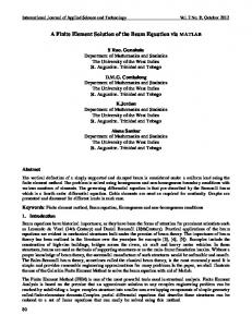
5. Results The results were first obtained for a beam clamped at both ends. The first graph represents a beam under the same load for various numbers of elements. The second graph displays the clamped beam under various loads. The code used to generate these results is given in Appendix A.
83
International Journal of Applied Science and Technology
Vol. 2 No. 8; October 2012
Graphs for the beam equation using homogenous boundary conditions Displacements for a clamped beam under various loads 0
-0.1
Displacement
-0.2
-0.3
-0.4
-0.5
load 25N load 50N load 75N) load100N
-0.6
-0.7
0
2
4
6
8 Number of elements
10
12
14
16
Clamped beam under a load of 75 Newtons for various number of elements 0
-0.02
Displacement
-0.04
-0.06
-0.08
-0.1 5 elements 10 elements 15 elements 20 elements
-0.12
-0.14
0
5
10
15
20
25
Number of elements
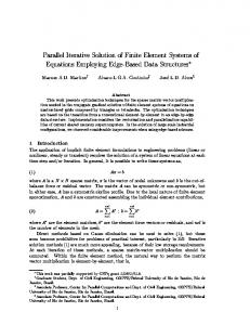
The boundary conditions were then changed to obtain results for a simply-supported beam. The graphical results were obtained for the same parameters as described for a clamped beam. The code used to obtain these results is given in Appendix B.
84
© Centre for Promoting Ideas, USA
www.ijastnet.com Simply supported beam for various number of elements
0
-0.5
Displacement
-1
-1.5
-2
5 elements 10elements 15elements 20elements
-2.5
-3
0
5
10 15 Number of elements
20
25
Simply suppoted beam under various loads 0
-1
Displacements
-2
-3
-4 load 100N load 75N load50N load25N
-5
-6
0
2
4
6 8 10 Number of elements
12
14
16
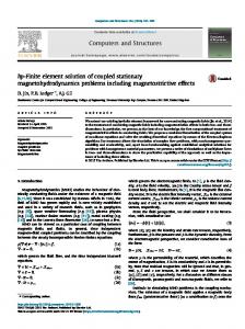
Graphs for the beam equation using non-homogenous boundary conditions
85
International Journal of Applied Science and Technology
Vol. 2 No. 8; October 2012
Clamped beam under varying forces 0
-500
Displacment
-1000
-1500
-2000
-2500 25 N 50 N 75 N 100 N
-3000
-3500
1
2
3
4
5 6 7 Number of elements
8
9
10
11
9
10
11
Simply supported beam under various loads 0 -2000 -4000
Displacement
-6000 -8000 -10000 -12000 -14000 -16000 -18000
1
2
3
4
5 6 7 Number of elements
8
6. Discussion The graphs display the results obtained for homogenous and non-homogenous boundary conditions. When the number of elements was increased for both clamped and simply-supported beams, the graphs yielded greater continuity which resulted from greater accuracy. That is to say the approximate solution was closer to the exact solution or there was less error as the number of elements increased. This is consistent with the theory of the FEM, as increasing the number of elements reduces the error, which in turn improves the accuracy of the solution. In addition, increasing the load also increases the displacement at each point on the beam. It should also be noted that the displacement for the simply-supported beam is greater than that of the clamped beam. Furthermore, the deflection for the non-homogenous boundary conditions was much more significant than that for the homogenous case. 86
© Centre for Promoting Ideas, USA
www.ijastnet.com
8. References A.J.M. Fereira (2009).Matlab Codes for Finite Element Analysis, Solids and Structures. D.Logan (2007). A First Course in the Finite Element Method (4th ed.). E.A. Witmer (1991-1992). "Elementary Bernoulli-Euler Beam Theory". MIT Unified Engineering Course Notes. pp. 5– 114 to 5–164. Euler-Bernoulli Beam Equation, http://en.wikipedia/Euler-Bernoulli-beam equation E.P Popov., Mechanics of Materials, Prentice-Hall, 1978. K.S. Thankane and T. Stys.(2009). Finite Difference Method for Beam Equation with Free Ends Using Mathematica. Southern African Journal of Pure and Applied Mathematics McKenzie, William (2006). Examples in Structural Analysis. Taylor & Francis. R.W Clough and J. Penzien .,Dynamics of Structures, McGraw-Hill, 1993. Seon M. Han, Haym Benaroya and Timothy Wei (1999). Journal of Sound and Vibration (1999) 225(5), 935}988 Seon M. Han, Haym Benaroya and Timothy Wei (March 22, 1999) (PDF). Dynamics of Transversely Vibrating Beams using four Engineering Theories. final version. Academic Press. http://csxe.rutgers.edu/research/vibration/51.pdf. Retrieved 2007-04-15. Y.Kwon and H.Bang(2000). The Finite Element Method using Matlab (2nd ed.).
6. Appendix Appendix A: Finite Element Code for Clamped Beam function [stiffness force displacements U reactions]= formstiffness(m,P) nodeCoordinates=linspace(0,1,m+1)'; xx=nodeCoordinates; L=max(nodeCoordinates); numberNodes=size(nodeCoordinates,1); xx=nodeCoordinates(:,1); E=1; I=1; EI=E*I; GDof=2*numberNodes; U=zeros(GDof,1); force=zeros(GDof,1); stiffness=zeros(GDof); displacements=zeros(GDof,1); for i=1:m; elementNodes(i,1)=i; elementNodes(i,2)=i+1; end for e=1:m; indice=elementNodes(e,:); elementDof=[ 2*(indice(1)-1)+1 2*(indice(2)-1) 2*(indice(2)-1)+1 2*(indice(2)-1)+2]; LElem=xx(indice(2))-xx(indice(1)); f1=4*[P*LElem/2 P*LElem*LElem/12 P*LElem/2 -P*LElem*LElem/12]'; force(elementDof)=force(elementDof)+f1; k1=EI/(LElem)^3*[12 6*LElem -12 6*LElem ; 6*LElem 4*LElem^2 -6*LElem 2*LElem^2; -12 -6*LElem 12 -6*LElem; 6*LElem 2*LElem^2 -6*LElem 4*LElem^2]; stiffness(elementDof,elementDof)=stiffness(elementDof,elementDof)+k1; end fixedNodeU=[1 2*m+1]';fixedNodeV=[2 2*m+1]'; prescribedDof=[fixedNodeU;fixedNodeV]; activeDof=setdiff([1:GDof]',[prescribedDof]); U=stiffness(activeDof,activeDof)\force(activeDof); displacements=zeros(GDof,1); displacements(activeDof)=U;
87
International Journal of Applied Science and Technology
Vol. 2 No. 8; October 2012
disp('Displacements') plot(U) jj=1:GDof; format [jj' displacements]; F=stiffness*displacements; reactions=F(prescribedDof); disp('reactions') [prescribedDof reactions]; U=displacements(1:2:2*numberNodes); plot(nodeCoordinates,U,'.') Appendix B: Finite Element Code for SimplySupported Beam function [stiffness force displacements U reactions]= formstiffness(m,P) nodeCoordinates=linspace(0,1,m+1)'; xx=nodeCoordinates; L=max(nodeCoordinates); numberNodes=size(nodeCoordinates,1); xx=nodeCoordinates(:,1); E=1; I=1; EI=E*I; GDof=2*numberNodes; U=zeros(GDof,1); force=zeros(GDof,1); stiffness=zeros(GDof); displacements=zeros(GDof,1); for i=1:m; elementNodes(i,1)=i; elementNodes(i,2)=i+1; end for e=1:m; indice=elementNodes(e,:); elementDof=[ 2*(indice(1)-1)+1 2*(indice(2)-1) 2*(indice(2)-1)+1 2*(indice(2)-1)+2]; LElem=xx(indice(2))-xx(indice(1)); f1=4*[P*LElem/2 P*LElem*LElem/12 P*LElem/2 -P*LElem*LElem/12]'; force(elementDof)=force(elementDof)+f1; k1=EI/(LElem)^3*[12 6*LElem -12 6*LElem ; 6*LElem 4*LElem^2 -6*LElem 2*LElem^2; -12 -6*LElem 12 -6*LElem; 6*LElem 2*LElem^2 -6*LElem 4*LElem^2]; stiffness(elementDof,elementDof)=stiffness(elementDof,elementDof)+k1; end fixedNodeU=[1 2*m+1]';fixedNodeV=[]'; prescribedDof=[fixedNodeU;fixedNodeV]; activeDof=setdiff([1:GDof]',[prescribedDof]); U=stiffness(activeDof,activeDof)\force(activeDof); displacements=zeros(GDof,1); displacements(activeDof)=U; disp('Displacements') plot(U) 88