JESUS A. DEL ALAMO, MEMBER, IEEE, AND WALID J. AZZAM. Abstract-A new simple technique to measure the parasitic source and drain resistances in ...
2386
IEEE TRANSACTIONS ON ELECTRON DEVICES. VOL. 36. NO. II. NOVEMBER 1989
A Floating-Gate Transmission-Line Model Technique for Measuring Source Resistance in Heterostructure Field-Effect Transistors JESUS A. DEL ALAMO,
MEMBER, IEEE, AND
Abstract-A new simple technique to measure the parasitic source and drain resistances in heterostructure field-effect transistors (HFET) is presented. The technique makes use of the unavoidable gate leakage current of a typical HFET under bias. Floating-gatemeasurements with current flowing from the source to the drain are carried out in a set of devices with different gate lengths. Extrapolation to zero gate length unequivocally and simultaneously yields both the source and drain resistances. No special test-pattern structure is required. The technique metal-insulator is demonstrated in I~.silAI,.4,As/n+-I~.seG~.4,As doped semiconductor field-effect transistors (MIDFET’s).
I. INTRODUCTION HE performance of heterostructure field-effect transistors (HFET’s) is severely affected by the parasitic source and drain resistances. In particular, the source resistance Rs degrades the intrinsic transconductance of HFET’s g, unless Rs < 1 /gm0. Reduction of the source resistance is imperative if high-performance devices are to be obtained. In order to optimize device design by having a low source resistance, its value must first be accurately measured. The most popular technique for the measurement of the source resistance is the transmission-line model (TLM) method [ 11, [2]. This technique utilizes a special test structure that consists of several metal contact pads located at various distances from each other on top of an n+-region identical to the one utilized for the source and drain of the FET [l], [2]. This technique yields, simultaneously, the specific transfer resistance (or contact resistance per unit length, the proper figure of merit for contact resistance in lateral devices such as FET’s) and the n -region sheet resistance. From the measurement of these two parameters and from a knowledge of the dimensions of the FET, one can estimate the source resistance of any device fabricated with the same technology. There are several problems with this approach. First, a special test structure that consumes valuable chip area is
T
+
Manuscript received May 12, 1989. J. A. del Alamo was partially supported by a Vinton Hayes Fellowship and W. J . Azzam was partially supported by the MIT Undergraduate Research Opportunities Program. The review of this paper was arranged by Associate Editor S . Tiwari. J. A. del Alamo was with the NTT LSI Laboratories, Atsugi-shi, Japan. He is now with the Massachusetts Institute of Technology, Cambridge, MA 02139. W. J. Azzam is with the Massachusetts Institute of Technology, Cambridge, MA 02139. IEEE Log Number 8930907.
WALID J. AZZAM
required. Second and most important, the typical TLM test structure is very different from a field-effect transistor structure because the standard TLM does not have a “gate.” As a result, the spreading resistance due to current crowding at the source end of the gate cannot be correctly measured by the TLM. In particular, the TLM test structure is very different from a typical recessed-gate HFET, in which an n+-cap is recessed before gate metal deposition [3]. This HFET structure is under intense research because it yields devices with very small source resistance. In fact, the highest microwave performance devices to date use this recessed-gate approach [4]. For this very important class of devices, the TLM completely fails to measure the source resistance. An improved version of the TLM recently has been proposed in an effort to eliminate this severe limitation of the conventional TLM. The gated TLM (GTLM) introduces a gate between the contact pads of the otherwise standard TLM [5]. This structure correctly takes into account the additional resistance due to current crowding that exists at the gate edge of a FET. However, because the method measures the total resistance from the source to the drain, symmetric structures in which the gate is exactly positioned in the middle of the source-to-drain gap are required. Such is seldom the result of a normal HFET fabrication process. A number of techniques for evaluating the source resistance of metal-semiconductor field-effect transistors (MESFET’s) through measurements on a single device have been proposed [6]-[14]. Unfortunately, most of these techniques require assumptions that do not apply to typical HFET’s. Several authors [7]-[9] based their techniques on Hower and Bechtel’s [6] in which the total source-to-drain resistance is measured. From this measurement, the sum of the source and drain resistances can be obtained if the behavior of the sheet resistance as a function of gate voltage is known. This is rarely known in the case of HFET’s. Techniques based on the “end” resistance [9]-[15] require assumptions of the behavior of the gate current as a function of the gate voltage. Gate current models that are utilized in MESFET’s [9]-[14] are unlikely to be correct for HFET’s [15]. In this paper we propose and demonstrate a new simple measurement technique that we denote the “floating-gate transmission line model” (FGTLM) technique. The
0018-9383/89/1100-2386$01.OO O 1989 IEEE
DEL ALAMO AND AZZAM: FGTLM TECHNIQUE FOR MEASURING SOURCE RESISTANCE
FGTLM utilizes actual HFET structures of various gate lengths. There is no need for a special test structure. The method is based on the fact that unavoidable gate leakage current flows in an HFET under bias. With current flowing from the source to the drain and the gate floating, the gate-to-source and the gate-to-drain voltages are measured in devices with different gate lengths. Extrapolation to zero gate length yields simultaneously and unequivocally both the source and drain resistances. We demonstrate the method in In,,52A10.48A~ /n+Iq,53Gao.47As metal-insulator-doped semiconductor fieldeffect transistors (MIDFET’s), a new device structure very promising for high-frequency large-signal microwave applications [16]-[18].
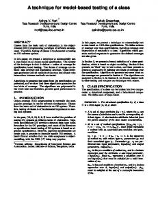
11. THEORY The theory that will be described in this paper applies to any HFET, be it a modulation-doped FET (MODFET), MIDFET, etc., and to nonheterostructure FET’s with some gate leakage, such as MESFET’s or junction FET’s (JFET’s). The geometry of the problem is shown in Fig. 1, which represents a generic HFET with either a two-dimensional electron gas or a doped channel, biased in the linear mode of operation. The intrinsic device shows a wide-bandgap material that is intended to isolate the metal gate from the channel. In a MESFET, the gate-to-channel isolation is provided by the depletion region associated with the Schottky junction. In a JFET, on the other hand, the depletion region of the p-n junction fulfills the same role. Common to all of these devices is the fact that the isolation is not perfect and a small leakage current flows between the channel and the gate at room temperature for any significant gate bias. In the linear mode of operation, in which a very small electric field exists along the channel, the proper equivalent circuit representation of the intrinsic HFET is a network of series resistances and parallel conductances, as schematically shown in Fig. 1. The series resistances characterize the resistance of the channel, while the parallel conductances represent the leakage between the channel and the gate. This network, which is associated with the intrinsic device, is in series with the parasitic source and drain resistances Rs and RD that connect the intrinsic device to the outside world. These are the resistances that we wish to determine. Even though the source and drain n+-regions are fabricated simultaneously, the respective distances between the source and gate, and the drain and gate, are in general different, and so are Rs and RD. The distributed resistance network associated with the intrinsic device can be analyzed using the transmission line model (TLM), as is commonly used in treating ohmic contacts [11. In Fig. 1, R represents the resistance per unit length of the channel (in units of ohms per micrometer) and G represents the gate-to-channel conductance per unit length of channel (in units of reciprocal ohms per micrometer). In the linear regime, with small biases applied
2387
[ \\nllOyd ’
SUBSTRATE
regton
Fig. 1 . Diagram of HFET showing the distributive resistance network associated with the intrinsic device.
to drain and gate, R and G can be considered independent of the x position in the channel (the discussion section explores the limits of this approximation). In this case, the complex resistive network can be represented by a simple inverted T-type resistive circuit. Symmetry implies that both wings of the inverted T must be identical. We denote this value by 4 Rch, or half the “channel resistance.” We also denote the column of the inverted-T resistive circuit by Rg, or “gate barrier resistance.” The complete equivalent circuit model for the HFET in the linear mode of operation is shown in Fig. 2, which also includes Rs and RD. In order to express Rch and R, as a function of R , G, and L G (with L G being the FET gate length), we must solve the TLM shown in Fig. 1. This is carried out in the Appendix. Rch and R, are found to be (see ( A l l ) and (A14) in the Appendix)
where Zo is the characteristic impedance (in ohms)
& -I
&=
(3)
and y is the propagation constant (in reciprocal micrometers) y =
JRG.
(4)
As (1) and (2) indicate, in general, Rch and R, depend on both the channel resistance R and the gate conductance G. In the case of Rch, this is because the metal gate partially shorts the channel through G and, therefore, contributes to conduction between the source and the drain. In the case of R,, this is because the channel resistance partially appears in series with the channel conductance. A plot of Rchand R g , normalized with Z,, is shown in Fig. 3. It is of interest to explore the limit values of Rch and R,. For short channel lengths or small gate conductance, yLG 1 implies --f
--f
In this case, the gate bamer resistance is made negligibly small, and the gate metal effectively shorts the channel. This results in a channel resistance of 2Z0, independent of gate length, where a Z, arises from the resistance of the channel to the gate at each of the two ends of the gate. The behavior of Rch and R, in this limit is clearly seen in Fig. 3. Using the equivalent inverted-T model for the intrinsic HFET shown in Fig. 2, we can now have three possible measuring configurations. They are schematically summarized in Fig. 4.
(9)
(11)
iRch
where the f d notation in brackets indicates a floating drain.
B. Floating-Gate Conjguration As Fig. 4(b) shows, current is now injected from the drain to the source. and the gate is left floating. There is no current through R,, and, therefore, the gate samples the voltage in the middle of the intrinsic channel. The three measured resistances are R , , ( f g ) = Rs
+ iRCh
(12)
Rgd(fg) =
RD
+ &Rch
(13)
Rds(fg) =
RS
+ RD + Rch.
(14)
C. Floating-Source Conjguration Now the situation is as shown in Fig. 4(c) in which current is injected from the gate to the drain and the source is left floating. The three measured resistances are: R , s ( f s ) = R,
(15)
Rgd(fs) = RD + i R c h R * ( f s ) = RD
+ iRch.
-k Rg
(16) (17)
2389
DEL ALAMO AND AZZAM: FGTLM TECHNIQUE FOR MEASURING SOURCE RESISTANCE
The nine measurements summarized above are not all independent of each other. In fact, since this is a linear circuit with three terminals, at most three measurements can be performed in an independent manner. As a result, at most, on a given HFET, we can determine R,, R, iRch,and RD iRch. The extraction of Rs and RD, therefore, cannot be carried out from one single device. An interesting situation appears when we have several devices that are identical to each other except for the gate length L G . If y is such that all of them are operating in the yLG