Keywords: Secure software design, RBAC, MAC, UML. 1. Introduction ... software/security engineer; clearly, a design can be in a ...... Secure Business Quarterly:.
A Formal Framework for Secure Design and Constraint Checking in UML Thuong Doan, Laurent Michel, and Steven Demurjian Department of Computer Science and Engineering University of Connecticut 371 Fairfield Road, Storrs, CT 06269-2155, USA E-mail: [thuong,ldm,steve]@engr.uconn.edu Contact Author: Thuong Doan
1
A Formal Framework for Secure Design and Constraint Checking in UML incorporates security into the early phases of requirements and design of the software process, its models, and tools [X04a, X04b, X04c, X05]. Furthermore, we also focus on the transition of the defined security into the development and deployment processes through the automatic generation of aspectoriented programs [Film05] that enforce the defined security [Y05a, Y05b]. Our research on security during the software process has focused on incorporating mandatory access control (MAC) and role-based access control (RBAC) into the unified modeling language, UML [Booc99]. In UML, while there are parallels between security and UML elements, direct support for security [OMG03] is not provided. Our approach via UML positions our work alongside other researchers [Algh03a, Epst99, Jürj02, Lodd02, Ray04, Shin00].
Abstract The design of software applications using the unified modeling language, UML, embodies an incremental process, transitioning a design from state to state over time. The integration of security into this process is critical to satisfy an application’s security requirements. This paper reports on a formal approach that incorporates role-based access control (RBAC), mandatory access control (MAC), and lifetimes, with constraint checking, into UML for time-sensitive application design. The resulting framework promotes secure software design by tracking an application’s security requirements as UML elements and connections are added, modified, and deleted. It also captures snapshots of each design state by checking constraints on security satisfaction properties for the design. Our objective in this paper is to detail the formal functional model with constraint checking that is able to track security for a UML design via the creation and maintenance of multiple design instances. To demonstrate the feasibility of our efforts, we report on the transition of the functional framework for secure design into Borland’s UML tool Together Control Center.
The motivation of our approach is rooted in the belief that the process of designing and integrating security in a software application must capture not only the current design state, but must be capable of tracking the entire design process as a set of design instances over time. Specifically, we argue that it must record both the valid design states and the design actions that were prohibited, to allow a full understanding of the design evolution over time. Moreover, the design tracking facility allows a security/software engineer to recover to an earlier design version that satisfies specific security constraints and/or extend another version branch from the one that shares some security constraints. Towards this goal, our previous work [X05] introduced state functions to track three subspaces of UML: elements, e.g., actors, use cases, class, methods, etc.; connections, e.g., inheritance, include, extend, etc.; and, application security requirements (SRs), e.g., Mutual Exclusion in RBAC. As UML elements, connections, and SRs are added, there is a simultaneous check of security consistency that records the security status of the state. However, this initial formalization [X05] assumed that the designer must insert all SRs into the design before starting to draw UML connections. This limitation forces unrealistic design behavior on a software/security engineer; clearly, a design can be in a state where some UML elements have SRs, some do not, and connections between them are incomplete.
Keywords: Secure software design, RBAC, MAC, UML.
1. Introduction The construction of secure software requires a unifying approach that begins at requirements and design and is transitioned through the deployment and maintenance processes. At the earliest stages, as security requirements are identified, security can be quantified as “… enforcing a policy that describes rules for accessing resources [Vieg02].” As the software process incrementally continues through design and development, the more often security is addressed, the better the security requirements can be achieved, which, as evidenced by [Hoo01], can improve the return on security investment for both attaining security assurance and tempering the cost of repairing security flaws after deployment. Delaying security to latter stages or delegating it to database administration results in software infrastructures that are untrustworthy, and unable to provide any degree of assurance to end-users and system administrators regarding security behavior. To address these failings, security concerns must be a first-class citizen in the software process at early and all stages.
The first contribution of this paper is to propose a general formal functional framework comprised of newly formalized state functions for the three sub-spaces that have uniform signatures that provide explicit error identification by number. In addition to overcoming the aforementioned limitation of [X05], this paper significantly extends [X05] by the inclusion of lifetimes
Our work on security for the software process [X04a, X04b, X04c, X05, Y05a, Y05b] has sought to provide an integrated, assured, and easy-to-use approach that
2
RBAC based systems. These efforts model security with UML, which contrasts to our approach to integrate RBAC, MAC, and lifetime directly into UML for secure application design and development. Third, UMLsec is an approach on formal analyses of multi-level security of message flows in subsystems of UML (sequence/state diagrams) [Jürj02]. Our work on MAC is similar to theirs, and their flow analysis is akin to our constraint checking. Fourth, in [Lodd02], SecureUML introduced new metamodel components (e.g., User, Role, Permission, ActionType, ResourceType, etc.) and authorization constraints expressed to generate a security infrastructure for RBAC. Their objective to define an extended modeling language based on UML for representing RBAC requirements is different from ours to integrate security and constraint checking into UML. Fifth, [Algh03a, Algh03b] present a framework that incorporates security into use cases; our work also includes class, and sequence diagrams. Overall, the major differences between our work and these efforts are our usage of lifetime for design artifacts (e.g., UML elements and connections) and tracking all design states/actions over time. This latter feature allows a security/software engineer to maintain all design states allowing recovery to an earlier design version that satisfies specific security constraints akin to source code control. Finally, note that there have been security efforts in semantic data [Smit91] and ER [Pern93, Pern98] models.
for SRs within the functional framework, allowing a designer to define applications security constraints with time-sensitive properties. The second contribution of this paper is a new approach for constraint checking that differentiates between: intra-element constraint checks related to security properties of a specific element and inter-element constraint checks for the connections between elements. Specifically, it proposes a new algorithm for RBAC constraint checking. Finally, the third contribution of this paper details a new design-time Security Satisfaction Design Support program that allows the designer to insert/update UML connections and SRs in any temporal order, for an increased flexibility during the design process. The remainder of this paper has five sections. Section 2 reviews background on MAC/RBAC, related research, and an example. Section 3 conceptualizes our framework for secure UML design and defines a formal model. Section 4 examines the constraint checking capabilities of model, including design-time and post-design checking, and an example of design state transformations. Section 5 reviews our prototyping effort with Borland's UML tool Together Control Center. Lastly, Section 6 concludes this paper and discusses the interplay of our two research thrusts on UML extended with security and constraint checking [X04a, X04b, X04c, X05] and the automatic generation of aspect-oriented programs that enforce the defined security [Y05a, Y05b].
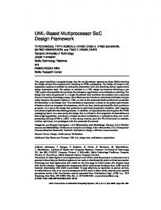
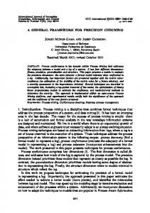
A Survey Institution that performs/manages public surveys will illustrate the ideas throughout the paper. After the raw survey data is collected, a senior staff adds a survey header into the database; senior or junior staffs add questions into the survey, may categorize questions, or add a question category. Questions with sensitive content are restricted to senior staff. Fig. 1 depicts a usecase diagram to create a new survey. The actor ac1: Staff has two children ac2: Junior Staff and ac3: Senior Staff. Generally, Staff can perform uc2: Add Question which includes uc4: Categorize Question, and can be extended to uc5: Add Question Category if a new category must be added. Only Senior Staff can perform uc1: Add Survey Header to include a new survey header and uc6: Add Special Question to include sensitive questions. Other facets of Fig. 1. will be considered as needed.
2. Background Concepts and Related Work In this section, we review background concepts on MAC/RBAC, related work, and an example to be used throughout the paper. In MAC (or Lattice-Based Access Control [Osbo00]), security levels (SL’s) form a lattice structure and are assigned to each subject (clearance CLR) and object (classification - CLS). The permission of the subject to perform some operation on the object depends on the CLR and CLS relation as dictated by: Simple Security Property (read down - no read up) [Bell75]; Simple Integrity Property (write down - no write up) [Biba77]; Strict *-Property (write equal') [Osbo00]; and Liberal *-Property (write up - no write down') [Bell75]. For simplicity, we use: unclassified (U), confidential (C), secret (S), and top secret (T) where U < C < S < T as example; our model applies to general partial orders. In RBAC [DdA, Ferr01], roles are assigned to users to specify the named assignments that those users can perform in the organization. Each role is authorized to perform some operations on certain objects.
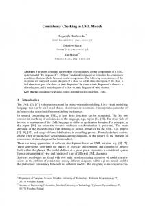
3. A Framework for Secure UML Design This section introduces a framework that integrates security into the requirement and design phases of the software process via UML. Conceptually, our model includes a four-component framework that maintains the security assurance as requirements/designs are defined and changed, as conceptualized in Fig. 2:
Related to our work, there have been other efforts on security for UML. First, in [Epst99] and [Shin00], UML is used to represent RBAC modeling and notation. Next, in [Ray03], UML elements are used to model MAC and
3
design process (security and non-security) for an application (see Component 3 below). It also supports the constraint checking to insure that the consistency of MAC, RBAC, and lifetime definitions on UML elements are checked against their connections with their admissibility or denial captured within each design state (see Component 4 below). • Component 3 - Persistent and Dynamic State Capturing and Maintenance: UML plus security extensions as realized within a formal functional model will provide the means to define and maintain a design state that tracks both the content of requirements/design for an application (security and non-security) and all actions taken by users as part of the process. Our work will support the specification of design actions as meta-functions on the current state and a design element to generate a new state, thereby reducing the design process to a sequence of state transformations that add, modify and/or delete UML elements, connections, and application’s security requirements. A design state-space is composed of three functional components for the (sub)spaces of: UML elements, UML connections, and the application’s security requirements.
Fig. 1. Use-Case Diagram for New Survey Entry
• Component 4 - Security Assurance via Constraint Checking: This final component involves the ability to offer a degree of security assurance via the checking of constraints as an application's requirements/design are created and changed over time. To accomplish this, we propose a satisfiable security design state that can be obtained in two modes: (1) design-time whenever the designer draws a new connection or edits an existing connection in a diagram, add/modify SRs and (2) post-design which is executed across all connections at once after the designer has reached a milestone or version in an application's UML diagrams.
Fig.2. A Framework for Secure UML Design • Component 1 - UML Extended with Security Capabilities: This aspect of our work incorporates security requirements and design into the software process by augmenting UML requirements definition (use-case diagram) and design (class and sequence diagrams) with visual and non-visual security extensions and constraints for RBAC, MAC, and lifetimes.
To augment these components, the framework also considers the impact of security on the software process. We have three assumptions that (1) the software design is an incremental process; (2) security is considered spirally along all of the phases, with assurance satisfied within each phase; and, (3) security should be seamlessly integrated into the process. We then define new properties of UML elements and connections to capture security features such as minimum and maximum security levels, role names, and lifetimes. We also introduce a new type of design elements, the security requirement (SR), to capture security constraints among UML elements and connections. In addition, since design is time-sensitive, lifetimes of design elements capture temporal characteristics of the design that impact security. The end
• Component 2 - Formal Functional Model: In support of our research goal, we define a formal functional model that captures UML requirements/design information (use-case, class, and sequence diagrams) and their constituent elements (use cases, actors, classes, attributes, methods, etc.) and connections (inheritance, association, include, extend, message, etc.) with security extensions (MAC, RBAC, and lifetimes). The functional model provides an infrastructure to capture an iterative and incremental
4
(id, k, lt, slmin, slmax) ∈ ∆ where id, k, lt, slmin, and slmax are its identification, kind, lifetime, minimum and maximum security levels (denoted as δ.id, δ.k, δ.lt, δ.slmin and δ.slmax), respectively. For a class c, we require c.slmin ≤ c.slmax (since a class is a container of attributes and methods) whereas for an element δ of other kinds, we only require δ.slmin = δ.slmax = δ.sl. To illustrate, in Fig. 1, use-case uc1: Add Survey Header with min and max SL = Secret (S) and LT = [“01/01/2005”, “12/31/2006”] would be (“uc1”, UC, [“01/01/2005”, “12/31/2006”], S, S) using Def. 3.1.
time of each element’s lifetime must be checked against the time of their design to verify whether that element is legally utilized (with respect to time dimension). In support of Components 2 and 3 of the framework, we need to include time in the representation of design states; identify the actions taken during design and their impact on the design state; and track the satisfaction of relevant security constraints. Section 3.2 introduces a function that models time dependent design states. It simply maps each design element ID and a specific design time to its content part and error part. The content part represents the “static” inherent properties of that element while the error part dictates whether that element is legally applicable at the specific design time. The projection of these mappings on the element ID at a specific design time (i.e., removing the design time dimension) yields the static design (applicable at that design time). To model user behavior, three kinds of actions on design elements (insertion, updating and deletion) are used. Each action is a function that maps the current design state and the affected element to the new state. Finally, in Section 3.3, we review MAC, lifetime, and static RBAC constraints in support of Component 4. This activity can be coupled with the design instances to allow a design rollback (undo) to a version of which the (previous) security constraints are satisfied. For secure software design to be successful, there must be demonstrated formal underpinning that provides guarantees to software and security engineers regarding the defined security.
In UML diagrams, elements are related via different connection kinds, ΛCK. From [X04a], connection kinds between UML elements x and y are specified from acyclic use-case diagrams (UCDs), acyclic class diagrams (CDs), and sequence diagrams (SDs) as follows: • In UCDs - Actor inheritance A_Ih: actor x inherits actor y; Actor-use-case association AU_Asc: actor x interacts with use-case y by association; Use-case inheritance U_Ih: use-case x inherits use-case y; Use-case inclusion U_Ic: use-case x includes use-case y; Use-case extension U_Ex: use-case y extends use-case x; • In CDs - Class inheritance C_Ih: class x inherits class y; Class-method defining CM_Def: the method y is defined in class x; • In SDs - Use-case-class utilization UC_Uz: class y is utilized in use-case x related to the concerned SD; Usecase-method utilization UM_Uz: method m is utilized in use-case x related to a SD using m; Actor-method utilization AM_Uz: method m is utilized by actor x in a SD; Method-method calling M_Ca: method x calls method y (via message passing in a SD).
3.1. Extended UML with Security In support of Components 1 and 2, we extend UML with security properties by characterizing each UML element with its identification, element kind, minimum and maximum security levels that form a range for MAC constraint, and lifetime (LT) as a duration in which the usage of that element is valid. Formally, we denote ΛID as an ordered set of identification (ID) labels that contains a sequence of distinct strings. Given η and η’ ∈ ΛID, ord(η) < ord(η’) means η appears before η’ in lexical order. Each design element will be uniquely assigned an ID in the order of creation time. We also denote ΛEK = {A, UC, Cl, M} as the set of element kinds for actor, use-case, class, and method, respectively. Let T be a set of discrete time of the form “month-day-year [hour:minute:second]” (as a subset Cartesian product of sets of integers), a lifetime lt is a time interval [st, et] where et and st ∈ T are the start time and end time (denoted as lt.st and lt.et), respectively, with et ≥ st (the point of time st occurs not after et). We denote the set of lifetimes as I. We also denote lt = ∅ if lt.st ≥ lt.et. Given these definitions, a UML element is:
Hence, ΛCK = {U_Ih, U_Ic, U_Ex, A_Ih, AU_Asc, C_Ih, CM_Def, UC_Uz, UM_Uz, AM_Uz, M_Ca}. Please note that only U_Ih, U_Ic, U_Ex, A_Ih, AU_Asc, C_Ih, AM_Uz, and M_Ca connection kinds are explicitly defined in UML [OMG03]. The others (CM_Def, UC_Uz, and UM_Uz) are explicitly defined in our model but implicitly implied from UML [OMG03]. For tracking the security satisfaction of UML diagrams (i.e., the ability of a given design in UML to satisfy security characteristics and constraints), we define connection kinds of a source and target element: Def. 3.2 (UML Connection) Let Φ = ΛID×ΛCK×I×ΛID×ΛID as the set of UML connections, a connection ϕ is a tuple (id, k, lt, ids, idt) ∈ Φ where id, k, lt, ids and idt are its ID, kind, lifetime, and the IDs of the source and target elements denoted as ϕ.id, ϕ.k, ϕ.lt, ϕ.ids and ϕ.idt (read as “the connection with ID label id is of kind k, expected applicable during the lifetime lt and connects the UML element with ID ids to element with ID idt”).
Def. 3.1 (UML Element) Let ∆ = ΛID×ΛEK×I×ΛSL×ΛSL as the set of UML elements, a UML element δ is a tuple
5
the extended sets ∆⊥ = {⊥} ∪ ∆, Φ⊥ = {⊥} ∪ Φ, and Θ⊥ = {⊥} ∪ Θ. Given a tuple e = (e1,..., ei,..., en}, πi e = ei denotes the projection of the ith entry of e (πj ⊥ = ⊥ for any j). For notational convenience, some formulas use χ standing for any symbol “∆”, “Φ”, or “Θ”. The expression (f x1… xn) means applying f on x1, …, xn.
The source and target UML elements are also called connection vertices. To illustrate, in Fig. 1, the connection (internally labeled as ϕ4) from ac3: Senior Staff to uc1: Add Survey Header via association with LT = [“01/01/2005”, “12/31/2005”] is referred to as (“ϕ4”, AU_Asc, [“01/01/2005”, “12/31/2005”], “ac3”, “uc1”). In support of RBAC, an actor (see Fig. 1) represents one organizational role as defined by the security officer. Generally, an application’s security requirement involved in i elements specifies some security constraint on these elements. In our work, we focus on SRs related to RBAC only. Let ΛSR be the set of security requirement kind, (ΛID)i = ΛID×…×ΛID (i times) and Θi = ΛID×ΛSR×I ×(ΛID)i (i= 2, 3,…), we have:
3.2. Design State Functions In support of Components 2 and 3, we must formalize a design state and provide the means to capture actions over time. Intuitively, when the designer creates, modifies, or deletes a UML element, s/he has changed the design to a new state with respect to the set of UML elements that previously existed. Over time, a UML design can be characterized as the set of all states where each state represents a specific design instance (snapshot in time). We denote Σ∆ as the set of the states of designed UML elements (called the ∆-space). When the designer adds, modifies, or deletes an application’s security requirements (SRs) and UML connections, the design changes from one state to another state with respect to SRs and UML connections, respectively. We denote ΣΘ and ΣΦ as the sets of the states of SRs (called Θ-space) and UML connections (called the Φ-space), respectively. Then, the design state is a triple (σ∆, σΦ, σΘ) ∈ Σ = Σ∆×ΣΦ×ΣΘ (the space of design states) where σ∆, σΦ and σΘ refer to the state of designed UML elements, designed UML connections, and SRs, respectively.
Def. 3.3 (Security Requirement) An application’s security requirement θ involved in i elements is a tuple (id, k, lt, η1, η2,…, ηi) ∈ Θi where id, k, lt, η1, η2,…, and ηi, are the ID label, kind of the security requirement, lifetime, and the i involved element’s IDs , respectively denoted as θ.id, θ.k, θ.lt,θ.els = {η1, η2,…, ηi}. (read as “the UML elements with IDs η1, η2,…, and ηi have an application’s security requirement of kind k with the label id and being expected applicable during the lifetime lt”). In this paper, however, we limit SRs ∈ Θ2 ∪ Θ3 and ΛSR = {DisU, MESRO, MESOR} for Disallowed Usage (as negative permission), Static Role-Objects Mutual Exclusion, and Static Object-Roles Mutual Exclusion, respectively, where: (id, DisU, lt, η1, η2) ∈ Θ2 means that element with ID η1 is not allowed to use element with ID η2 during lt; (id, MESRO, lt, η1, η2, η3) ∈ Θ3 indicates that an actor with ID η1 is not allowed to use both elements with IDs η2 and η3 during lt, where for normalization purpose, ord(η2) < ord(η3) when writing the SR (id, MESRO, lt, η1, η2, η3); and (id, MESOR, lt, η1, η2, η3) ∈ Θ3 indicates that actors with ID η1 and η2 (ord(η1) < ord(η2)) are not allowed to use element with ID η3 at the same time during lt. For example, (“SR1”, DisU, [“01/01/2005”, “12/31/2008”], “ac2”, “uc1”) is used to describe a DisU , labeled as “SR1”, that prohibits ac2 (Junior Staff) from use of uc1 (Add Survey Header) from “01/01/2005” to “12/31/2008” and (“SR2”, MESRO, [“01/01/2005”, “12/31/2006”], “ac2”, “uc2”, “uc3”) for a MESRO , labeled as “SR2”, that prohibits ac2 (Junior Staff) from simultaneous use of uc2 (Add Question) and uc3 (Approve Question) from “01/01/2005” to “12/31/2006”. We denote Θ = Θ2 ∪ Θ3 as a set of SR instances.
The design process reduces to a sequence of state transformations to add, update, and/or delete UML elements, SRs, and UML connections. An action α (add, update or delete) is a transformation of a state (σ∆i, σΦi, σΘi) to another state (σ∆i+1, σΦi+1, σΘi+1). The set of actions is denoted as . The component states σ∆, σΦ, Θ and σ are represented with functions. The state function σχi captures the information of all of the design elements at the state i. Intuitively, in any design state, we want to have the ability to query the state for particular elements (as identified by ID), and that query may either fail (ID not defined or ID not defined at a particular time) or succeed (ID defined). Thus, given an ID label and a specific design time, σχi can determine if that ID label is not associated with an existing design element, or return the tuple of an existing element with that ID, (including whether that element is validly useable at the given design time) and error status. Define Err ={0, 1, 2,…} as the set of error numbers where “0” is used as an initial value (for initial state) and “1” means no error. We define the signature of state functions as:
���
The set of design elements (including UML elements, UML connections, and security requirements) is denoted as = ∆ ∪ Φ ∪ Θ. We denote the null element as ⊥, and
Def. 3.4 (State function signatures) The signature of state functions for • UML elements:σ∆: ΛID×T → ∆⊥×Err
6
• UML connections:σΦ: ΛID×T → Φ⊥×Err • Application’s security requirements: σΘ: ΛID×T → Θ⊥×Err. The initial state function σχ0 ≡ nullf(η, t) = (⊥, 0). When the design is started from scratch, there exists no UML element, connection or security requirement. In state i, the status of a design element η at design time t is r = (π1 r, π2 r) = σχi η t. We call π1 r and π2 r the content and error parts of status r. We have the following cases: (1). Empty content part (π1 r = ⊥): there is no element e, such that e.id = η (e’s ID as η) at the time t.
functions represent security assurance rules corresponding to the security constraint type and the currently concerned tier. For example, in Tier 1 (use-case diagram), we only need to check the security constraints with rules related to use cases and actors. Intuitively, they can be described as: • MAC Constraint. The constraint CstrMAC(σi, ϕ, t) for a connection ϕ from x to y in the design state σi at t requires that the domination of the security level range of the source x over that of the target y depend on the chosen MAC properties (e.g., Simple Security) (see [X04b] for dealing with different MAC properties). • Lifetime Constraint. The constraint CstrLT(σi, ϕ, t) for a connection ϕ from x to y in the design state σi at t requires that the end time of the non-empty overlap of the LTs of the connection ϕ and those of its source and target elements occur after t. • RBAC Constraint. The constraint CstrRBAC(σi, , t) for a SR in the design state σi at t requires that all paths of UML connections between UML elements participating in the SR cannot exist at the same time (i.e., the SR cannot be violated as a result of paths connecting related UML elements). Note that CstrRBAC(σi, , t) needs to check whether the SR will be effective after t, that means, whether the end time of the non-empty overlap of the LTs of and those of its involved UML elements (of which the IDs are in the set .els) occurs after t. If is not effective, we do not need to enforce , and CstrRBAC(σi, , t) simply yields true.
(2). Non-empty content part (π1 r ≠ ⊥): there is an element e such that e.id = η. If π2 r = 1 then e is applicable at the time t, else (π2 r ≠ 1) e is not applicable at the time t with error number π2 r. Designing reduces to an interleaving of actions to produce a state (σ∆i, σΦi, σΘi) and evaluate its state function σΦi to determine its security satisfaction. For convenience, σn denotes (σ∆n,σΦn,σΘn).
3.3. Security Constraints Checking In support of Component 4 for constraint checking, we assume there are three different security/software design tiers for the UML: - Tier 1 focuses on the use-case diagram; - Tier 2 emphasizes the class creation and associations between the classes that are utilized by each use case; - Tier 3 represents the creation of a UML sequence diagram with actor/method and method/method interactions. Given a state in each tier, we need to perform two types of constraint checking on design elements: intra-element and inter-element checking.
4. Security Satisfaction Design Support In Section 3, we presented the infrastructure of our framework to track the state of an extended UML design with MAC, lifetime, and RBAC constraints. Collectively, the material provides the formal functional model that supports the definition of security within UML (Section 3.1), the capturing of design state (Section 3.2), and the checking of constraints (Section 3.3). Given this model, we must define a mean for the security/software engineer to know when the design is acceptable (with respect to security) in order to move forward through successive phases of the software process. Intuitively, when the security/software engineers feel content with the design, each design element must be applicable to use (i.e. the error part of its status is 1) at the design time (the first necessary condition). Further, for each facet of security (MAC, lifetime and RBAC), the related design elements also must satisfy the corresponding rules of the appropriate security which includes other necessary conditions related to constraint checking. We refer to these conditions as security satisfaction properties. Thus, an important question to be addressed involves how we know that the design holds for these expected properties.
Intra-element checking is for constraints related to properties of a specific element. Using intra_chk functions for the design space, the intra-element check verifies whether the lifetime of that element is still admissible at the design time, which includes a check to see if its properties (e.g., security levels for UML elements or the element components) are also legitimate at the design time. Due to space limits, we omit the actual details of the intra_chk functions and some other functions to be discussed later on. Inter-element checking is for constraints related to relations of element connections, and has three categories: MAC, lifetime, and RBAC. We introduce functions for MAC and lifetime constraint checking on UML connections, and RBAC constraint checking on an application's SR in a specific design state at some design time as: CstrMAC: Σ×Φ×T → Boolean, CstrLT: Σ×Φ×T → Boolean, and CstrRBAC: Σ×Θ×T → Boolean. These
7
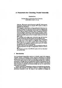
explanation. When the designer attempts to draw a connection ϕ3 from ac1 to uc3, the function Response reports an error in State 8 at design time t since the application’s SR MESRO has been added at State 5 (ac2 is prohibited from simultaneously utilizing uc2 and uc3). Then, ac2 inherits ac1 (State 7) while ac1 is intended to utilize both uc2 and uc3 in State 8. So, ac2 will also be able to utilize both which violates the application’s security requirement MESRO. Thus, State 8 is not RBACsatisfiable (hence not a satisfiable security state) which is reported by the security satisfaction design support program.
Our answer is to provide a Security Satisfaction Design Support (SSDS) program with two modes of checking constraints for security compliance: the design-time mode (using dSSDS program) for real-time checks as the designer creates and alters a UML diagram; and, postdesign mode (pSSDS program) for an on-demand check of an entire design version across all of an application's UML diagrams. The basic idea of the SSDS program is to perform intra-consistency checks and inter-consistency checks on the effect of the action with the affected element in the current design state at a specific design time. The outcome of these checks will determine the properties of the design in terms of security compliance.
��
Table 1. A Design State Construction Process Example.
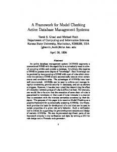
In support of SSDS, we begin by specifying the function Response(α: , e: , σ:Σ, t:T): (Σ×Err) as the effect of an action α on a design element e in the state σ, at time t. Response calculates the result state σres and an error flag for the action that depends on the type of action and whether the constraints hold in the result state σres and the affected element e. The dSSDS program PDT is intended to always be active within the design environment (e.g., UML tool), and is specified in pseudo-code as:
�
Attempted Action
New State
Effect
0:(σ∆0,σΦ0,σΘ0) (The initial state) Add ac1 1:(σ∆1,σΦ1,σΘ1) σ∆1 adds ac1, σΦ1=σΦ0, σΘ1=σΘ0. ∆ Φ Θ Add uc2 2:(σ 2,σ 2,σ 2) σ∆2 adds uc2, σΦ2 =σΦ1, σΘ2 =σΘ1. Add uc3 3:(σ∆3,σΦ3,σΘ3) σ∆3 adds uc3, σΦ3 =σΦ2, σΘ3=σΘ2. ∆ Φ Θ Add ac2 4:(σ 4,σ 4,σ 4) σ∆4 adds ac2, σΦ4 =σΦ3, σΘ4 =σΘ3. Add a MESRO to 5:(σ∆5,σΦ5,σΘ5) σ∆5=σ∆4, σΦ5=σΦ4, prohibit ac2 from σΘ5 with a Static simultaneous use Role-Objects Mutual of uc2 and uc3 Exclusion SR on ac2 with uc2 and uc3. Draw a connection 6:(σ∆6,σΦ6,σΘ6) σ∆6 =σ∆5, σΦ6 with an ϕ1 from ac1 to association from ac1 uc2 to uc2, σΘ6= σΘ5. See Note 1. Draw a connection 7:(σ∆7,σΦ7,σΘ7) σ∆7=σ∆6, σΦ7 with inheritance from ac2 ϕ2 from ac2 to inherit ac1 to ac1, σΘ7=σΘ6. See Note 2. ∆ Φ Θ Draw a connection 8:(σ 8,σ 8,σ 8) σ∆8=σ∆7, σΦ8 with invalid connection, ϕ3 from ac1 to uc3 σΘ8 =σΘ7. Notes: 1. The connection ϕ1 is valid in State 6 (at the design time t = “06/01/2005”) as the function Response on ϕ1 yields no error - all three MAC, RBAC and LT constraints hold at t. 2. The connection ϕ2 is valid in State 7 as the function Response on ϕ2 yields no error - all three MAC, RBAC and LT constraints hold at t.
PDT(σ: Σ, t: T){ // σ is the beginning satisfiable security state // t is the design time specified by the designer σnow = σ err_no = 0 // No error is defined yet while designer performs action α on e = Response(α, e, σnow, t) if err_no ≠ 1 then ReportError(err_no) else {Materialize e in the design; σnow = σtemp} end while} If err_no is 1 (i.e., no constraint violation has occurred), the system commits to the new design elements, e.g., draws the connection between the two elements in the diagram. Otherwise, ReportError( ) alerts the designer and the system ignores the effect of the action (e.g., the line for the connection on the screen is not allowed to be drawn), returning the system to the previous satisfiable security state. In this way, the system always maintains satisfiable security states with all applicable design elements. Note that the removal of connections at any point during the design does not affect its validity. To illustrate this process, Table 1 provides a synopsis of the actions taken at design time t = “06/01/2005” by a software engineer who: creates new UML elements - two use-cases and two actors (States 1 to 4); adds SRs - a mutual exclusion (State 5); adds two valid connections one between an actor and a use-case (ϕ1 in State 6) and one between actors (ϕ2 in State 7); and fails in a connection attempt - from an actor to a use-case (ϕ3 in State 8). The table omits the formal representation of actions, state functions, and constraints, to streamline the
Note that PDT assumes that the designer starts from a satisfiable security state. In practice, the scenario can be more complex and this assumption may not hold. For
8
This paper has presented a formal functional framework for modeling design states, tracking actions that transform design states, and MAC, RBAC, and lifetime constraintchecking for UML connections. To accomplish this, in Section 3, we introduced a functional model to represent UML elements, UML connections, application security requirements, and security constraints for MAC, RBAC and lifetime properties of UML elements and connections that are checked as a design is created. Using the model, Section 4 introduced a satisfiable security design state, and proposed a Security Satisfaction Design Support (SSDS) program for checking the security compliance of states both at design time and post design. Lastly, Section 5 briefly reviewed our in-progress integration of the work of this paper into the UML tool Together Control Center. Our ongoing work is in a number of areas. First, we are working to prove assertions regarding the various constraints (Section 3.3), to definitively demonstrate that our functional model can quantitatively be used to prove assertions for constraints such as mutual exclusion, MAC, etc., for a given design state. Second, we investigating the complexity in the worst case, for both post-design and ondemand checking programs (Section 4), which is critical as we seek to apply our framework to realistic applications comprised of hundreds (and more) of UML elements and connections. Third, we seek to augment our work on UML design extensions to consider the newly adopted UML version 2 (www.uml.org/#UML2.0), in particular, by considering new interaction diagrams for dynamic security constraints akin to Jürjens’ work on state diagram [Jürj02]. Fourth, we are exploring improvements to lifetime that can capture periodical time expressions (similar to [Bert00]). Lastly, we continue to work closely with the effort on generating aspect-oriented security enforcement code [Y05a, Y05b] to fully integrate our research efforts to range from requirements to design to development to deployment. As part of this effort, we continue transition our completed work into a joint prototype (see Section 5) as proof of concept, with a plan to transition all of our prototyping effort to the Eclipse platform in the coming year (www.eclipse.org).
instance, a designer could start with a satisfiable security state and import one or more UML diagrams without security constraint-compliance checking into the design, or may turn off PDT if the connections are too complex to always maintain a satisfiable security state. In these situations, it is necessary to use the post-design pSSDS program to perform the overall constraints checking, which works for any design regardless of whether constraint-compliance checking has occurred. pSSDS is meant to be explicitly invoked by a designer at regular intervals. The formal description of the pSSDS program, PPD is omitted due to space limits. Intuitively, PPD simulates the designer’s actions by re-inserting each design element into a design state if it is found applicable. PPD is akin to a security compiler being executed on a design instance.
5. Model Architecture and Prototype Effort Over the past two years, we have been working on a prototype that features a model architecture containing a set of interacting modules, including: • UML Design Tool is the graphical user interface (GUI) for the designer to input/edit UML diagrams. Currently, we employ Borland's Together Control Center with Open APIs for Java and modular plug-in structure for UML design augmented with security definition and both design-time and post-design checking. This module materializes the Component 1 of our framework (see Section 3 for our framework). • Internal UML Structures Storage stores in-core representations of UML structures extended with security properties and synchronously writes them to persistent storage (an Oracle RDBMS) in order to improve searching capabilities and support a multidesigner working environment. This module that represents the design state and the trigger mechanism reflecting the design actions is corresponding to Component 3 using the formalization of Component 2 of our framework. • Security Constraint Checking Module enforces security constraints on UML elements and connections. If a constraint is violated, it pops up an error message and abandons the intended design element. Otherwise, the design element is created in the GUI UML design tool and updates the database. This module realizes the Component 4 of our framework. • AOP Code Generation: This module generates aspectoriented programming enforcement code based on the security that has been defined using the extended UML. These modules are being integrated into Borland's UML tool Together Control Center (TCC), which we have reported in our earlier work [X05a] in greater detail.
6. Conclusions and Ongoing Research
9
[Pern98] G. Pernul, et al. Modelling Data Secrecy and Integrity. IEEE Trans. On Data and Knowledge Engineering, 26(3), 1998. [Ray03] I. Ray, et al. Using Parameterized UML to Specify and Compose Access Control Models. Proc. of the 6th IFIP Working Conf. on Integrity & Internal Control in Info. Systems, 2003. [Shin00] M. Shin and G. Ahn. UML-Based Representation of Role-Based Access Control. Proc. of the IEEE 9th Intl. Wksp. on Enabling Technologies: Infrastructure for Collaborative Enterprises, 2000. [Smit91] G. Smith. Modeling Security Relevant Data Semantics. IEEE Trans. on Software Engineering, 17(11), 1991. [Vieg02] J. Viega and G. McGraw. Building Secure Software. Addison-Wesley, 2002. [X04a] (Hidden author names) A published paper on RBAC/MAC security with UML, 2004. [X04b] (Hidden author names) A published paper on MAC and UML for secure software, 2004. [X04c] (Hidden author names) A published paper on UML design with security integration, 2004. [X05] (Hidden author names) A published paper on stateful design for secure information systems, 2005. [Y05a] (Hidden author names) A published paper on a new UML notation for RBAC permission assignment and enforcement with aspect-oriented programming, 2005. [Y05b] (Hidden author names) An accepted on a formal model for RBAC using aspect-oriented programming, 2005.
7. References [Algh03a] K. Alghathbar and D. Wijesekera. AuthUML: A Three-phased Framework to model Secure Use Cases. Proc. of the Wksp on Formal Methods in Security Engineering, 2003. [Algh03b] K. Alghathbar and D. Wijesekera. Consistent and Complete Access Control Policies in Use Cases. Proc. of UML 2003, LNCS, 2003. [Bell75] D. Bell and L. La Padula. Secure Computer Systems: Mathematical Foundations Model. M74-244, Mitre Corp., 1975. [Bert00] E. Bertino et al. Temporal authorization bases: From specification to integration. Journal of Computer Security, Vol. 8, 2000, pp. 309-353. [Biba77] K. Biba. Integrity Considerations for Secure Computer Systems. TR-3153, Mitre Corp., 1977. [Booc99] G. Booch, et al. The Unified Modeling Language User Guide. Addison Wesley, 1999. [DdA] (Hidden author names) A published paper on user role-based security model for a distributed environment, 2001. [Epst99] P. Epstein and R. Sandhu. Towards A UML Based Approach to Role Engineering. Proc. of the 4th ACM workshop on Role-based Access Control, 1999. [Ferr01] D. Ferraiolo, et al. Proposed NIST standard for role-based access control. ACM Trans. on Info. and System Security, 4(3) 2001. [Film05] R. Filman, T. Elrad, S. Clarke, and M. Aksit (eds.), Aspect-Oriented Software Development. AddisonWesley, 2005. [Hoo01] K. Soo Hoo, et al. Tangible ROI through Secure Software Engineering. Secure Business Quarterly: Defining the Value of Strategic Security. 1(2), 2001. [Jürj02] J. Jürjens. UMLsec: Extending UML for Secure Systems Development. Proc. of UML 2002, LNCS, 2002. [Lodd02] T. Lodderstedt, et al. SecureUML: A UMLBased Modeling Language for Model-Driven Security. Proc. of UML 2002, LNCS, 2002. [OMG03] OMG. OMG-Unified Modeling Language, v.1.5. UML Resource Page, March 2003 (www.omg.org/uml/). [Osbo00] S. Osborn, et al. Configuring Role-Based Access Control to Enforce Mandatory and Discretionary Access Control Policies. ACM Trans. on Info. and System Security. 3(2), May 2000. [Pern93] G. Pernul, et al. The Entity-Relationship Model for Multilevel Security. Proc. of the 12th International Conference on Entity-Relationship Approach, 1993.
10