supports component-based technology by specifying a control class ... architecture controller to meet the manufacturing needs of the automotive industry. 2.
A Framework for component-based CNC Machines John Michaloskia, Sushil Birlab , George Weinertc , and C. Jerry Yend a National b c
Institute of Standards and Technology, Gaithersburg, MD
General Motors North American Operations, Warren, MI
Lawrence Livermore National Laboratories, Livermore, CA d
General Motors Power Train Headquarters, Pontiac, MI ABSTRACT
Open-architecture technology is ushering in new advances in the world of computer numerically controlled (CNC) machines. Yet, some major benefits of open-architecture technology have failed to materialize due to the lack of a standard openarchitecture specification. We propose an open-architecture framework to fill the specification void. The proposed framework supports component-based technology by specifying a control class hierarchy, plug-and-play components and a design framework. This framework can be used to build applications ranging from a single-axis device to a multi-arm robot. An example application applying the framework is documented. Keywords: API, architecture, classes, CNC, control, framework, object-oriented
1. BACKGROUND A major advance is underway within the CNC community toward open, component-based, controller technology.1 Much as openness revolutionized the PC industry, openness has the potential to revolutionize the CNC industry. Currently many controllers are marketed as open. However, to realize truly open-architecture benefits, controller components and interfaces must be standardized. An open-architecture standard allows integrators to mix and match components from different vendors. With an open-architecture standard, controllers can be built from best-value components from best-in-class services. For parts manufacturing, this ability leads to better integration of process improvements and increased satisfaction of application requirements. The “Open Modular Architecture Controller” (OMAC) white paper spells out the industry requirements for an openarchitecture controller to meet the manufacturing needs of the automotive industry.2 In response to these requirements, the OMAC Application Programming Interface (API) workgroup was formed. As members of the Open Modular Architecture Controller (OMAC) API workgroup, the workgruop’s goal has been to define a specification for open, component-based controllers. On the basis of our evaluation, we believe that a specification based on an object-oriented framework offers the best hope in achieving open, component-based controllers. In this work we describe an object-oriented framework for designing and implementing open-architecture control systems. In our context, the term framework is used to mean a specification for an integrated set of software components. An open system framework is a framework that promotes interface reuse based on a public interface specification.3 In the OMAC framework, classes define components of the system. Class instances or objects are used to implement the components. The framework classes are derived from a decomposition of a generic controller into a class hierarchy. Framework classes are then grouped Published in Proceedings of SPIE: Sensors and Controls for Intelligent Machining, Agile Manufacturing, and Mechatronics, December 1998, pp.132-143. No approval or endorsement of any commercial product by the authors or their employers is intended or implied. Certain commercial equipment, or materials are identified in this report in order to facilitate understanding. Such identification does not imply recommendation or endorsement by the authors or their employers, nor does it imply that the materials or equipment identified are necessarily the best available for the purpose. This publication was prepared, in part, by United States Government employees as part of their official duties and is, therefore, a work of the U.S. Government and not subject to copyright.
into OMAC API modules that become plug-and-play components. Within the framework, a controller design is generated by selecting different implementations of the OMAC modules. A survey of the industry finds other open-architecture standardization efforts. Open System Architecture for Controls within Automation Systems (OSACA) is a message-based open-architecture effort that has developed a reference architecture and communication scheme directed at equipment controllers.4 Open System Environment Consortium (OSEC) has produced a message-based, open-architecture specification also, which is based on the Factory Automation Equipment Description Language (FADL) for exchanging messages in a distributed, agent-based, networked environment.5 These efforts use a message-based approach to specification. Message-based communication is at a lower level of abstraction than an API-based framework. In the OMAC API framework, communication between objects is achieved by method invocation. Nevertheless, when distributed communication is needed, a proxy agent is used to cross a domain boundary.6 We feel this approach hides the lower-level communication details thus improving software quality. The proxy-based approach offers a model conducive to both local and remote object interaction. In the following sections, we will review major aspects of the OMAC framework. First, we start by describing the notion of a framework and why it is useful. We then apply information modeling to the application domain, which yields a class hierarchy and the concept of a “module” as a necessary prerequisite for plug-and-play. Following this discussion, architecture design and detail design within the OMAC framework will be reviewed. We then look at the behavior model for the framework including discussion on finite state machines, events, and collaboration.
2. FRAMEWORK MODEL An object-oriented framework builds controllers as a collection of objects that encapsulate algorithms and data representations. This is in contrast to the procedural software approach where the behavioral procedures and the data structures exist as separate entities that are only loosely connected. The benefits of modularity, reusability and extensibility were decisive in selecting an object-oriented framework as the specification approach. This contrasts with the procedural approach where there is difficulty extending and specializing functionality; difficulty in factoring out common functionality; difficulty in reusing functionality that results in duplication of effort; and, difficulty in maintaining the non-encapsulated functionality. Frameworks enhance modularity by encapsulating volatile implementation details behind stable interfaces. Modularity is based on information hiding where an object has a public API that other objects can use to communicate with it. The object can maintain a private representation that can be changed at any time without affecting the other objects that depend on it. Further, you don’t need to understand the inner object workings in order to use it. Ultimately, framework modularity improves software quality by localizing design and implementation changes. Frameworks provide extensibility by allowing new or modified objects to be developed. Using inheritance, frameworks allow you to modify or change any object’s behavior. Frameworks provide the specifications for new objects allowing you to build new components out of smaller objects. Frameworks allow you to integrate components that are system-tailored for your particular application. Assimilating the new or modified objects within the framework is achieved by three principal mechanisms: associations (relationship between different types), subtypes (relationship between like types including inheritance) and aggregation (subpart relationship within a larger part). Frameworks promote reusability so that application developers do not have to start over each time. Frameworks are built from a collection of objects. Given standard object interfaces, reuse of both the design and the code of a framework is possible. Additionally, frameworks define the environment in which the objects operate. Since each object makes assumptions about its environment, these assumptions must be the same or there is no way of using them together. Frameworks define an environment containing a range of standard mechanisms including data exchange, error handling, and interobject cooperation.
3. INFORMATION MODELING The domain of interest is discrete parts manufacturing where the applications range from low-end, single-axis machines to high-end machines requiring multi-axis, coordinated motion control and sensor-based process control. A high-end, machine controller makes decisions regarding part sequencing, tooling, and part locations, and it monitors the operation of the machine under its control. Representative applications include Computer Numerical Control (CNC) machines for cutting, inspecting and grinding. Although these applications differ in terms of their processes, there is a great deal of overlap from a control point of view of functionality in motion and process control.
Machining systems/cells; workstations
Plans
Simple machines; tool-changers; work changers
Processes
Fixtures Other tooling Machine tool axis or robotic joints (translational; rotational)
Axis groups
Axis components (sensors, actuators)
Control components (pid; filters)
Geometry (position, coordinate frame; circle) Units (meter)
Measures (length)
Kinematic structure Containers (matrix)
Primitive Data Types (int, double, etc.) Figure 1. Controller Class Hierarchy
3.1. Class Hierarchy A framework embodies generalized domain functionality based on analysis and synthesis of a wide range domain applications. Frameworks use a class hierarchy for domain modeling. Class hierarchies define static relationships between classes sharing common behavior. At the lowest level, the definition of the software class closely corresponds to the physical objects in the application domain. More abstract classes are defined in terms of the lower classes. Ultimately, all classes are members of a hierarchy of classes united via inheritance or association relationships. To derive a class hierarchy, a decomposition of a generic controller is performed. The decomposition spans many levels of abstraction and has the elements for motion control and discrete logic necessary to coordinate machining, to mill parts, and to sequence operations. Figure 1 portrays the class hierarchy derived from a controller decomposition. At the lower levels, the classes are the building blocks that may be found in multiple modules. For example, the class definition of a Geometry “position” would be found in most modules. As one moves up the hierarchy, framework classes broaden their scope to define device abstractions for such motion components as sensors, actuators, and PID control laws. As the scope broadens however, not all software objects have physical equivalents. Objects such as axis groups are logical entities only. Axis groups hold the knowledge about the axes whose motion are to be coordinated and how that coordination is to be performed. Services of the appropriate axis group are invoked by user-supplied plans. Object-oriented techniques can help greatly in defining a specification. We found the object-oriented feature of inheritance crucial in managing complexity. For example, when defining a control law class, there exist many options to implementing control laws including PID, Fuzzy Logic, Neural Nets, and Nonlinear. Each control law option has different nomenclature and features. The question arises, “When do we stop defining our class definitions?” We used object-oriented inheritance to control the breadth and scope of class definitions. Inheritance is a specialization mechanism which allows a derived class to inherit properties of a base class. Inheritance has many benefits. It helps manage the scope of capabilities, which reduces complexity. It allows different terminology (e.g., weights versus gains) based on need. Specialization provides a technique to handle evolving technology by allowing new derived class to be defined when necessary. Objects of the derived class have access to data and methods of base classes without the need to redefine them. We started by defining base classes that modeled the general data and behavior. Subsequently, only highly-demanded subclasses, such as PID in our case, were derived with the knowledge that inheritance offers a straightforward mechanism for expanding the specification. Inheritance was also used to institute levels of conformance. Level 1 classes constitute base functionality seen in current practice. Level 2 classes inherited all the data and behavior of the level 1 class definitions, but added extensions to handle advanced functionality. Higher levels constitute functional capability seen in emerging technology, but unnecessary for simple applications. Levels of complexity were seen as critical in allowing different specification conformance levels.
3.2. Modules A primary goal of the OMAC API specification was to enable “plug-and-play.” Plug-and-play on a per-class basis as defined in a class hierarchy is not economically feasible since the level of granularity of a class is too fine. Instead, a coarser granularity component, which we call a module, is necessary for realizing plug-and-play. To be plug-and-play, a module must satisfy the following requirements. (1) A module must be a significant piece of software used in a component-based controller. (2) A module must contain a grouping of similar classes. (3) A module must support a well-defined API, states, and state transitions. (4) A module must be replaceable by any piece of software that implements the API, states, and state transitions. The OMAC API framework extracts fourteen modules from the class hierarchy. The set of OMAC Modules and their general responsibilities include: Axis Modules responsible for servo control of axis motion, transforming incoming motion setpoints into setpoints for the corresponding actuators. Axis Group Modules responsible for coordinating the motions of individual axes, transforming an incoming motion segment specification into a sequence of equi-time-spaced setpoints for the coordinated axes. OMAC Base Class Base class for control OMAC modules providing uniform state model with methods for start-up and shutdown, uniform name and type declaration, and error-logging interface. Capability Object derived from Control Plan Units to which the Task Coordinator delegates for specific modes of operation that correspond to traditional operating modes (AUTO, MANUAL, and MDI). Control Law Components responsible for servo control loop calculations to reach commanded setpoints. Control Plan Units Derived from FSM class. When the FSM is passed between modules it is called a ControlPlanUnit. Received ControlPlanUnits are then used within a module for control flow. Control Plan Generator Modules responsible for translating part programs into a Control Plan. Discrete Logic Modules responsible for implementing discrete control logic or rules characterized by a Boolean function that maps input and internal state variables to output and internal state variables. Kinematic Model Modules responsible for kinematic mechanisms, connections, coordinate frame transformations and kinematic solutions. Human Machine Interface Modules responsible for handling data remotely, command, and event service of an internal controller module. I/O Points Collection of I/O responsible for reading from input devices and writing to output devices through a generic read/write interface. Machine-to-Machine Modules responsible for connecting and communicating to controllers across different domains. Process Model Component containing dynamic data models to be integrated with the control system. Task Coordinator Modules responsible for sequencing operations and coordinating the various motion, sensing, and eventdriven control processes. A modules has other characteristics that clarify its intent within the framework. Interchangeable modules may differ in their performance levels. Modules may provide more functionality (added value) than required in the specification. Specialization of a module interface is the mechanism to achieve additional functionality. A controller may have more than one instance of a module. Modules can be explicitly control-related (e.g., Axis) or inheritance-related encapsulating common functionality (e.g., OMAC Base Class.) Modules can run as separate threads and contain multiple threads of execution. Modules do not need to run as separate threads so systems can be built from a single thread of execution. Modules may be used to build other components. For example, a discrete mechanism, such as a tool-changer component, can be built using OMAC modules.
ControlPlanUnit
Control Plan Generator
ControlPlanUnit
Discrete Logic
Task Coordinator
Methods
ControlPlanUnit
IO POINTS ... IO POINTS
ControlPlanUnit ControlPlanUnit
Process Model
Methods
Axis Group
ControlPlanUnit
Kinematics
Methods Methods
Motion Axis Group
Kinematics
ControlPlanUnit
ControlPlanUnit
Process Model
Methods
Spindle Axis Group
Process Model Tight Synchronization of Motion and Spindle
Methods
Kinematics
Methods
AXIS AXIS Methods
IO POINTS
Methods
Methods
IO POINTS
Control Law
Methods
Control Law
. .
. . IO POINTS
IO POINTS
Figure 2. Drilling Example
4. DESIGN ISSUES A system design is divided into two phases. The first phase is architectural design and deals with system decomposition into OMAC Modules. The second phase is called detailed design and is responsible for detailing individual object API, that is, the object attributes and methods. In this case, the design uses the published object API or extends the API to suit the application.
4.1. Architecture Design The design architecture describes the decomposition of the application into individual modules. A design architecture highlights the static relationships between modules (as opposed to the data flow.) The OMAC framework does not specify a reference architecture so composing a design architecture from OMAC modules is left to the developer. We felt it was imperative that the framework be scalable and allow the designer the freedom to build any size system. With this freedom, OMAC systems can start small, stay small, or be pieced together into a larger system. For example, an embedded system with a small footprint is possible. Another system possibility is to start with an operator controlling several IO points, add an axis at a time, integrate the axes into an axis group to eventually evolve into a full-blown 5-axis controller. This design freedom offers much flexibility, but without guidance, can be perplexing.
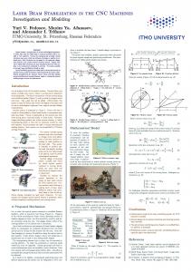
4.2. Architecture Example An example describing a CNC programmed for one-axis drilling will be developed. A typical one-axis drilling workstation would perform some hole-working operations, e.g., drilling with a spindle drill-head, boring a precision bore, counter-boring the bored hole, probing the (axial) location of the counterbored shoulder. Figure 2 illustrates the modules and component relationships for a drilling application. One Axis module is necessary for motion control and another Axis module is required for Spindle control. Spindle drive components are assumed to provide a facility for setting spindle speed and direction and to start and stop spindle rotation. Coordinated motion of the motion and spindle is supplied by three Axis Group modules. One Axis Group independently controls the motion and one Axis Group independently controls the Spindle. The final Axis Group supercedes the first two to synchronize coupled control of the Motion and Spindle (shown as shaded with dashed line connections). Generally, the Spindle Axis will not need a Control Law, however, when it is synchronized with motion it will require servo-driven control. In the diagram, the Task Coordinator exists to provide program control. The Control Plan Generator module translates a part program into Control Plan Units. The primary command communication between modules is reflected in the diagrams by
DESIGN ARCHITECTURE
Task Coordinator
Control Plan Generator
-C-
-C-
Arc
Line
Line
Axis1
P
V
T
P
V
T
IO Pts
Arc
IO 1
M A J Manual AutomaticJogging
-C-
Axis Group
Axis2
COTS COMPONENTS
-x-
Nurb
-xSercos Software
IO 2
...
Weave
Nurb
-x-
IO
P PID
Weave
V PD
IO ... IO CanBus
T PP IO
IO ... IO D/A
Figure 3. Design Framework showing the keyword “Method” or “ControlPlanUnits” (which uses a method to pass it) next to an arrow. The Discrete Logic Module handles part loading and unloading, as well as machine state (e.g., temperature, estop). To improve predictability and reduce variation, the Process Model module exists to integrate sensing and control to detect tool breakage by monitoring spindle torques and thrust forces. The Kinematics module models the workspace and handles different tool offsets and part placements.
4.3. Detail Design The detailed design is concerned with the component assembly, especially integration and configuration. The detailed design configures module responsibilities, performance, timing, and logical- to-physical mappings. Controllers are integrated into a set of connected-module-instances that use other module services through the published API. Much of module integration depends on an infrastructure which is defined as the services that tie the modules together and allow modules to use platform services.
4.4. Infrastructure An infrastructure is defined as the collection of services that tie modules together and includes platform services. The infrastructure is intended to hide specific hardware and platform dependence; however, this is often difficult to achieve. The infrastructure deals primarily with the computing environment including platform services, operating system, and programming tools. Platform services include such items as timers, interrupt handlers, and inter-process communications. Programming tools include compilers, linkers, and debuggers. The OMAC API does not specify an infrastructure because many of the infrastructural issues are outside the controller domain and are better handled by the domain experts. Further, it is more cost-effective to leverage industry efforts rather than to reinvent infrastructure technologies. Because there are so many competing infrastructure technologies, OMAC API has chosen to let the market decide the course of the infrastructure definition. As such, to achieve plug-and-play module interchangeability, a commitment to a Platform + Operating System + Compiler + Loader + Infrastructure suite is necessary for it to be possible to swap OMAC modules.
4.5. Detail Design Example We will consider the detailed design for the drilling example discussed previously. We assume that the detailed design is the responsibility of the system integrator who analyzes individual modules for performance and functional requirements. Based on this analysis, the system integrator selects modules and module components from the available, commercial, off-the-shelf (COTS), technologies. Figure 3 illustrates the design framework with the Design Architecture enumerating the necessary modules and module components and the COTS Components. If desired modules are not available as COTS technology or are available but do not meet the requirements, then the system integrator must develop modules on his own. Once the pieces are in place, the application developer configures the modules and “puts the pieces together” by linking the purchased COTS “.o” object files. Modules are configured based on their reference mapping to other modules. For the Axis modules in the example, the application developer has the possibility to select position (P), velocity (V), or torque (T) Control Law modules in software, hardware or some combination of hardware and software. For software P control, a Control Law object from the Software set
is selected. For hardware P control, a Control Law object from the Sercos7 set is selected. The applications developer is also responsible for mapping the logical I/O points onto physical devices. Modules are also configured based on the selection of Control Plan Units (CPU) to define a module responsibilities. Within the example, there is a Task Coordinator module that has containers for inserting Capability CPU (in the figure represented by a -C- framed by a diamond). The Capabilities include Manual, Automatic or Jogging. The application developer is free to put one or more of these Capabilities into the Task Coordinator or to develop a unique Capability. For Control Plan Generator and Axis Group, the application developer is provided Line and Arc CPU already but can plug in a Non-uniform Rational B-spline (NURB) CPU or a Weave CPU.
5. BEHAVIOR MODEL Building a controller is based on assembling instances of OMAC modules into a system. In general practice, controllers are modeled as a distributed system of concurrently active objects – although in implementation a single thread of execution is possible. Active objects do not need to receive a message to be in the “active” state and govern their execution by internally managing one or more independent threads of control. To reinforce the notion of plug-and-play, we use the term active module in lieu of “active object.” Examples of controller active modules include: (1) Axis modules, (2) Axis Group modules, (3) Discrete Logic modules, and (4) Task Coordinator modules. Active modules may delegate to passive modules that do not possess threads of control and that depend on an active module for the execution of their functions. Examples of passive modules include (1) Kinematic Model modules, and (2) Control Law modules.
5.1. State Machine Model The behavior of an active module is modeled as a finite state machine (FSM). In the FSM model, the world is thought of as being in a definite state at any given time. The set of the possible states is known as the state-space. Time itself is discretized to a sequence of relevant moments. There exists the notion of changing from one state to another between moments. The concept of change is expressed in terms of state transitions from one state to another state, as time passes. Typically, there is a set of allowed transitions from any given state. For our domain, we assume that a controller has a finite set of states, so that the term finite state machine more accurately describes our model. We further assume that a controller can be modeled as deterministic FSM whereby states can exhibit only one transition sequence for a given state and a given input. The OMAC framework assumes that a complex FSM can be simplified by grouping states into a hierarchical FSM.8 A “flat” FSM can suffer from combinatorial growth of state transitions; such is the case when every normal state has a state transition to an error state in the FSM. The hierarchical FSM can be used to simplify the error state combinatorics by nesting all the states that have error transitions inside a higher-level “normal” state. Hierarchical FSMs help reduce the excessive amount of state transitions. Of greater interest to the OMAC framework is the recursive nesting of FSMs. This functionality differs from a hierarchical FSM and more closely resembles running a program within a job-control shell. In the shell, suspending the shell causes the program to suspend also. A good example of this job control model can be found in the Sematech “Job Manager/Managed Job” model.9 In the recursive nesting model, both the shell and the job are FSMs, but the shell FSM is a supervisor to the job FSM. OMAC API does not dictate the number of levels of recursive nesting. In general, an outer administrative FSM exists to handle activities that include initialization, startup, shutdown, and, if relevant, power enabling. OMAC API defines the OMAC Base Class module to provide a uniform administrative state model across modules. To enter into a lower FSM, the module enters into the “executing” state. In the “executing” state, client/server coordination uses a lower FSM for coordination. This lower FSM is module- and application-dependent. This lower FSM, in turn, can have a FSM embedded within it so that further nesting of embedded FSMs is possible. Figure 4 shows the nesting of FSM levels. Within the figure, the FSM icon is represented by a rectangle inside a diamond. The dotted FSM icon represents an optional FSM. The nesting of one or more, lower-level, operational FSMs is possible depending on system complexity. Within the nesting of the FSM shown in Figure 4, the operational FSM handles different CNC modes corresponding to “auto,” or “manual.” The designer of a particular control system determines the number of nested FSM levels, depending upon the complexity and organization of the controlled system. For example, at the operation level for part programming, there may be even another FSM level to handle a family of parts. The lowest level FSM, or dominion FSM, monitors the current focus of control. The dominion FSM “rules” over lower level objects. There may be one or more dominion FSMs at the lowest level within an OMAC module, which will be covered later in the computational model section.
pause
Event Source
... Administration FSM reset, init, ready, executing, paused
pause
Operation FSM auto, manual
pause
Dominion FSM busy, idle paused, running
Figure 4. Recursive Nesting of FSM
5.2. Events Within a FSM, actions are associated with states and/or state transitions. Associating an action with a state is categorized as a Moore machine. Associating an action with a state transition is categorized as a Mealy machine. We adopt the Mealy machine as our model since it is better suited for an event-driven system. Event-driven systems correlate actions to discrete changes in the world. We characterize change to be modeled as an event, which triggers a state transition. For OMAC API, method invocations cause events to be propagated from the client to the server. Events are evaluated within the highest level FSM and then forwarded recursively through each lower level FSM. For example, we will assume that the Administrative FSM in Figure 4 is in the “executing” state and the “executing” state accepts a “pause” event to trigger a state transition to the state “paused.” Referring to Figure 4, the receipt of a “pause” event at the highest Administration level causes the state transition to “paused.” If the Operation FSM supports a “pause” method then this method is invoked and the event evaluated. This event evaluation and recursive forwarding of the event may cross module boundaries and propagate all the way to the “bottom” FSM in the application controller. Overall, event handling is both distributed as well as recursive. Such event dispatching contrasts to traditional frameworks characterized by centralized event handling known as inversion of control.10
5.3. Computational Model A general computational model exists for characterizing all OMAC active modules. Figure 5 illustrates this model, which supports a mechanism to receive and queue client requests. Client requests can be either events or FSMs. FSMs received by a server can replace existing FSMs or be added to the dominion list. The next section on Control Plan Units covers the concept of collaboration using FSM. Event Source
EVENT
MODULE
ADMINISTRATION
FSM
FSM
DOMINION
FSM
...
FSM
FSM
STATE
FSM
Figure 5. Module Computational Paradigm
STATE
...
As outlined previously, each OMAC module can support levels of recursive FSM. The OMAC API module may also have one or more FSM simultaneously executing on a dominion FSM list. Each FSM on the dominion list is equivalent conceptually to a concurrent thread of state logic. FSMs on the dominion list can operate independently or not. The ability to have multiple FSMs executing concurrently is especially useful for process modeling. Within the Axis Group module for example, the dominion list could contain a FSM for motion control as well as a FSM for sensor integration. Additionally, FSMs can be added to the dominion list that are “task-independent,” such as data logging. Further, the dominion list could support more complex architectures, such as RCS,11 with FSMs for sensor processing, world modeling, planning, value judgment and behavior generation. The OMAC framework identifies three types of FSM that can exist on the dominion list: Transient FSMs perform a fixed amount of work within a certain period. Transient FSMs execute cyclically and are removed from the dominion list when an internal condition is satisfied. An example of a transient FSM, is a motion segment FSM which has a beginning and an end. When the FSM “is done”, the FSM is removed from the dominion list. Resident-Cyclic FSMs execute “forever” and perform a function periodically. Resident-cyclic FSMs execute repeatedly with no internal completion condition. One example of a resident-cyclic FSM is a programmable logic controller (PLC) operation that turns the oil/slides pump on/off every five minutes. Resident-Event-driven FSMs execute once when an event triggers their execution. An example of a Resident-Event-driven FSM is turning an I/O point on or off. Applying these concepts to the Axis Group for example, transient FSMs are used for controlling different motions (e.g., line, arc) while resident-cyclic FSMs are used to integrate probe readings or handle data logging. Different OMAC API modules have different FSM dominion list sizes and different types of FSM. The Discrete Logic module has a multi-item FSM list containing resident-cyclic and resident-event-driven FSM. The Discrete Logic multi-item dominion list is analogous to a PLC scan list to handle IO. The Axis Group has a multi-item dominion list with one or more transient motion FSM and potentially one or more resident-cyclic Process FSM. The Axis module has a one-item transient motion FSM dominion list.
5.4. Distribution of FSMs Equivalent, application functionality can be achieved with different distributions of FSMs within a controller. Depending on the circumstances, tight coupling or loose coupling can be used to coordinate logic and motion. Tight coupling is achieved by placing resident-cyclic FSM on the dominion list. Loose coupling is achieved by placing resident-cyclic FSM in a separate thread, under the scheduler, used for all the other OMAC modules (which are resident-cyclic FSMs.) As an example, consider the integration of a Probe sensor data with an Axis Group to modify motion control. There are at least three ways for incorporating the Probe FSM into the system. (1) The Probe FSM is placed in the Discrete Logic module to be run at a given period. The probe could run at the same period as the Axis Group or be oversampled. This is an example of loose coupling. (2) The Probe could be a Process Model resident-cyclic FSM that runs inside of the Axis Group at the same frequency as the Axis Group. This is an example of tight coupling and is illustrated in Figure 6. (3) The probe could run as standalone resident-cyclic FSM scheduled like other OMAC modules. The probe FSM could run at a slower, faster or the same frequency as the Axis Group. This is an example of loose coupling and is illustrated in Figure 7.
5.5. Collaboration In the OMAC framework, FSMs are used for controlling behavior and also serve as data. When events are sent from the client to the server and contain FSM as data, the FSM data is called a ControlPlanUnit (CPU). A ControlPlanUnit is a FSM, but the internal representation is not important to the OMAC framework. Instead, CPU are defined with a simple state management API hiding unnecessary FSM details. The crux of the CPU class is a few fundamental methods as seen in the following Interface Definition Language12 (IDL) code: interface ControlPlanUnit { ControlPlanUnit executeUnit(); boolean isDone(); };
Axis Group
ADMINISTRATION
Kinematics
FSM share data
DOMINION
Motion CPU
Probe CPU
Probe
calc fwd/reverse
STATE
Axis
STATE
Figure 6. Example Tight Coupling Probe Architecture ADMINISTRATION
Axis Group Kinematics
FSM
calc fwd/reverse
DOMINION Motion CPU
Axis
Process Model compensation
...
STATE
Probe CPU
Probe
STATE
Figure 7. Example Loose Coupling Probe Architecture The ControlPlanUnit is an example of the Command pattern.13 To evaluate the current state, an active module invokes the executeUnit() method, which causes the FSM to perform a state evaluation. Three examples of modules derived from Control Plan Unit are: (1) Capability, which is a CPU to which the Task Coordinator delegates for specific modes of operation corresponding to traditional CNC operating modes (AUTO or MANUAL); (2) Motion Segment, which is a transient CPU used by the Axis Group module for motion control; and (3) Discrete Logic Unit, which is a transient or resident-cyclic CPU for discrete logic control. A series of linked CPUs forms a Control Plan. A Control Plan is a general-purpose representation of a control program. OMAC API defines the Control Plan Generator module, which is responsible for translating programs written in applicationspecific languages (e.g., CNC RS274D14 part programs) into the more general Control Plan. To enable program translation, program logic CPU are defined to mimic control constructs such as if/then, or while statements. CPUs serve as data by being passed between active modules. Subsequently, such CPUs then serve as the FSM logic within the behavior model. A ControlPlanUnit can contain other ControlPlanUnits. When activated, a CPU can send embedded CPUs to lower level servers. Thus, a CPU contains “intelligence” and understand how to coordinate and sequence the lower level logic and motion modules. Figure 8 illustrates the collaboration model as a CPU propagates through a simplified control system. In step (a) the Control Plan Generator module translates a part program written in RS274D into a Control Plan. In step (b) the Task Coordinator uses getNextControlPlanUnit to retrieve a CPU. In step (c) the Task Coordinator does an executeUnit on this CPU. Step (c) may be repeated several times, as in the case when the CPU may have to synchronize with lower level modules (e.g., such as waiting until all current Motion Segments have first completed). After synchronization, step (d) occurs whereby the CPU running within the Task Coordinator appends a reference to the Motion Segment CPU onto the Axis Group motion queue using the method setNextMotionSegment. This is an example of an embedded CPU being passed to a subordinate module. Once the Motion Segment CPU is loaded onto the Axis Group queue, it waits for activation. Once activated, the Axis Group periodically calls the Motion Segment CPU executeUnit() method until the isDone() condition is true.
nit () tro lPl an U
(c) executeUnit()
Control Plan Unit
gm Se
Motion Segment
n io ot
Control Control Control Plan Unit Control Plan Unit Control Plan Unit Plan PlanUnit Unit
tM ex
Task Coordinator
tN se
(b )
(a) translate()
) (d
N10 G01 G91 F10 N20 X10 Y10 Z10 N30 X1 Y1 Z1 N40 M30
ge tN ex tC on
RS 274 Part Program
en t()
Control Plan Generator Motion Motion Motion Segment Segment Segment
Axis Group Motion Motion Motion Segment Motion Motion Segment Segment Segment Segment
Figure 8. Collaboration Model
6. DISCUSSION Defining an open-architecture, controller specification that is flexible and extensible is hard. Making it cost-effective and real-time is even harder. In tackling this challenge, we used an object-oriented framework to define our open-architecture specification. We used a framework largely due to its advantages in enabling COTS plug-and-play component technology to added, replaced, reconfigured, or extended based on the functionality and performance required. This paper highlighted only some of the more important aspects of the OMAC framework. Interested readers can find more information about the framework at the OMAC API website.15 Choosing a framework for defining the open-architecture specification is not without risks. Frameworks are an objectoriented technology that have been used successfully elsewhere for some time, but are starting only now to make in-roads in the manufacturing domain. We recognize that industry has found it difficult to adopt the framework paradigm, due to entrenchment in the legacy of prior implementations, the “comfort zone” of past practice and culture, the investment hurdle to effect change, and the shortage of skilled resources. However, the future is bright; and more and more manufacturing companies are shifting to this paradigm.
REFERENCES 1. F. Proctor and J. Albus, “Open-architecture controllers,” IEEE Spectrum 34, pp. 60–64, June 1997. 2. Chrysler, Ford Motor Co., and General Motors, Requirements of Open, Modular, Architecture Controllers for Applications in the Automotive Industry, Dec. 1994. White Paper – Version 1.1. 3. R. E. Johnson, “Frameworks = (Components + Patterns),” CACM 40(10), pp. 39–42, 1997. 4. OSACA, “Open System Architecture for Controls within Automation Systems.” See Web URL: http://www.osaca.org, 1996. 5. OSEC, “Open System Environment Consortium.” See Web URL: http://www.sml.co.jp/OSEC, 1996. 6. M.Shapiro, “Structure and Encapsulation in Distributed Systems: The Proxy Principle,” in 6th International Conference on Distributed Computing Systems, IEEE 6th International Conference on Distributed Computing Systems , pp. 198–204, IEEE Computer Society Press, May 1986. 7. IEC, IEC1491 - SERCOS (SErial Real-time COmmunications System) Interface Standard. International Electrical Commission, Geneva, 1995. 8. D. Harel, “On Visual Formalisms,” CACM 31(5), pp. 514–530, 1988. 9. SEMATECH, Computer Integrated Manufacturing (CIM) Application Framework Specification 1.5. SEMATECH, 2706 Montopolis Drive, Austin, TX 78741 U.S.A., 1997. 10. M. Fayad and D. C. Schmidt, “Object-Oriented Application Frameworks - Introduction,” CACM 40(10), pp. 32–38, 1997. 11. J. S. Albus, “Outline for a theory of intelligence,” IEEE Transactions on Systems, Man, and Cybernetics 21, pp. 473–509, May-June 1991. 12. Object Management Group, Framingham, MA, The Common Object Request Broker: Architecture and Specification, Revision 2.0, July 1995.
13. E. Gamma, R. Helm, R. Johnson, and J. Vlissides, Design Patterns: Elements of Reusable Object-Oriented Software, Addison Wesley, Reading, MA, Oct. 1994. 14. Engineering Industries Association, Washington, D.C., EIA Standard - EIA-274-D, Interchangeable Variable, Block Data Format for Positioning, Contouring, and Contouring/Positioning Numerically Controlled Machines, February 1979. 15. OMAC API Workgroup, OMAC API Set. See Web URL: http://isd.cme.nist.gov/info/omacapi.