E LEKTROTEHNIŠKI VESTNIK 78(1-2): 79-84, 2011 E NGLISH EDITION
A Graphical User-interface Controller for the Biomedical High-voltage Signal Generator Denis Pavliha, Matej Reberšek, Damijan Miklavčič University of Ljubljana, Faculty of Electrical Engineering, Tržaška 25, SI-1000 Ljubljana, Slovenia E-mail:
[email protected] Abstract. The Graphical User Interface (GUI) of the biomedical equipment is expected to perform reliably and to assure fast response at a maximum level of safety. We designed a user-friendly GUI to control the high-voltage signal generator (electroporator). Electroporation is a phenomenon in which biological cell membrane permeability becomes transiently increased due to exposure to an electric field caused by high-voltage electric pulses. Electroporation is used in electrochemotherapy, gene electrotransfer and non-thermal tissue ablation. A customdeveloped high-voltage signal generator (electroporator) was designed as a modular solution embedding a MiniITX platform with the Microsoft Windows CE 5.0 operating system. A custom application was designed in Visual Basic .NET to control the output power stage via a Universal Serial Bus 2.0 connection. The device is compact and controlled using a touch-screen display. Due to the shellless operating system the user does not feel to be using a Personal Computer at all. Namely, the GUI layout is designed intuitively needing no knowledge of the device properties or electronics. Keywords: graphical user interface (GUI), biomedical devices, computer software, Windows CE, electroporation
1 INTRODUCTION Electroporation is a phenomenon in which biological cell-membrane permeability becomes transiently increased due to exposure to high-voltage electric pulses [1]. This phenomenon causes molecules to easily traverse the plasma membrane, which can be useful for chemotherapy of tumors [2] and gene therapy [3]. Electroporation has been used in electrochemotherapy (ECT) since the 80’s [4] to improve efficiency of chemotherapeutic agents due to increased permeability of cell membranes achieved by means of high-voltage electric pulses [2, 5]. If pulse parameters (amplitude, duration, number of pulses and repetition rate) are adequately chosen [6], the effect of electroporation is reversible and the cell will reestablish its initial state afterwards [7]. The amplitudes of the typical electric pulses for ECT application range from 40 to 600 V (or even more – depending on the electrode geometry), their duration is between 20 and 1000 µs and they can be usually applied in a sequence of up to 64 pulses [8]. Another efficient electroporation application is gene electrotransfer where enabling the use of to some extent longer pulses or a combination of high- and low-voltage pulses leads to DNA transfer into cells [9, 10]. Moreover, irreversible electroporation is another possible application of electroporation used to perform non-thermal tissue ablation [11]. Recently, however, special attention has been given to the effects of high-amplitude (up to 10 kV) electric pulses of durations in the nanoseconds range (i.e. nanosecond electric pulses or nanopulses) [12]. Nanopulses induce increased permeability of not only the outer but also the internal membranes of biological cells [13], which can Received 31 January 2011 Accepted 22 February 2011
lead to cell apoptosis. To perform electroporation with nanopulses [14], a different type of the electroporator is needed. This is mainly because regular output power stages of the currently available electroporators cannot deliver pulses of durations shorter than 1 µs [15], and therefore cannot electroporate internal membranes of cells. Since commercial nanosecond high-voltage signal generators are not available yet, we started to build our own electroporator that would be capable of producing such pulses, principally on the model of other research groups [16]. The electroporator that we developed [17] is intended for laboratory experiments in the field of electroporation to provide the basic knowledge on how cells respond and which mechanisms are involved when exposed to high-voltage nanosecond pulses [18]. For the electroporator to operate properly, an adequate User Interface (UI) needs to be designed. Since the electroporators are devices used in biomedicine, it is vital that UI is reliable, fast responsive [19] and safe for use. When designing an easy-to-use electroporator, a Graphical User-interface (GUI) controller should be used to reduce the time needed to learn how to operate a new device and increase the operator’s effectiveness. Therefore, we designed a GUI controller that enables the user to efficiently use our nanopulse electroporator.
2 MATERIALS AND METHODS 2.1. Hardware platform When starting the process of constructing a GUI controller, the designer first needs to choose a hardware platform [19]. Generally, the processor-based hardware platforms can be divided into two major groups:
80
PAVLIHA, REBERŠEK, MIKLAVČIČ
general-purpose computers (personal computers – PC) and special-purpose computers (embedded systems) [20]. Because a GUI controller is basically an embedded system that performs only few predefined functions, a special-purpose computer as the hardware platform seems an adequate choice. In fact, the embedded systems have been the primary choice for many userinterface designers in the past [15]. Using an embedded microprocessor board is in any case an advantage with respect to the device compactness; a single embedded system means less electronics in the device. Also, all peripheries can be programmed within a single environment. However, the microprocessor of the system needs to perform both the calculation part of the output signals (engine) and the displaying part of the system (user interface). Consequently, modularity of software is truncated since multiple functions are forcibly joined together by the designer, which can be considered as a disadvantage. To eliminate this disadvantage, modularization of both hardware and software components is a good solution enabling achievement of several additional advantages:
VIA Eden processor (VIA Technologies, Taiwan, 2001) running at a frequency of 1.2 GHz. VIA EPIA M700 also provides a socket for DDR SDRAM and incorporates an integrated graphics controller with a Video Graphics Array (VGA) output. A Network Interface Controller (NIC) is available as well as an embedded Universal Serial Bus 2.0 (USB 2.0) controller. To avoid using a Hard Disk Drive (HDD), a CompactFlash (CF) card was used as the main storage media instead. Compared to HDD, there is no mechanical delay when using CF cards since they perform data storage based on flash technology. Also to be noted is important that when the system is physically transported, the probability of damaging its components is reduced. Moreover, CF cards provide complete TrueIDE functionality meaning that they are fully compatible with ATA/ATAPI (Advanced Technology Attachment - Packet Interface). Therefore, all we need is CF to the Integrated Drive Electronics (IDE) adapter in order to connect the CF card to the mainboard and use it as HDD.
2.2. Output power stage -
distribution of functions along the system components assures better allocation of the system resources,
-
simple replacement of damaged hardware lowers maintenance expenses; only broken components need to be replaced,
-
when designing multiple different systems that perform similar functions, the existing designs of hardware or software components can be reused and reintegrated into new systems. Hence, development costs of new devices are lower and the time-to-market shorter.
Nevertheless, a modular solution can also be obtained using a general-purpose personal computer (PC), although there are certainly concerns about using it as a GUI controller. Evaluating hardware capabilities of such systems, it is appropriate to use x86-based mainboards commonly including powerful processors running at a frequency of 1 GHz or above and embedding a fast Double Data Rate (DDR) Synchronous Dynamic Random Access Memory (SDRAM). In order to equip our nanopulse electroporator with a GUI controller, we first had to choose hardware that would comply with our intentions of designing a modular solution. Hence, we chose to design our GUI controller based on a Mini-ITX platform (VIA Technologies, Taiwan, 2001). We used a VIA EPIA M700 mainboard which is an x86 processor-based PC mainboard of a 17 x 17 cm size. The board embeds a
The output power stage of the electroporator is designed on a modified Blumlein configuration that enables a high repetition rate of a variable duration of either bipolar or unipolar high-voltage pulses. The developed electroporator consists of high-voltage power supply (DC-DC in Fig.1), double charge and discharge switches (Switch and Discharge in Fig.1) and Blumlein transmission line (Coaxial Transmission Line in Fig.1) with the load. The Blumlein transmission line is charged by a high-voltage power supply via two charge switches providing high pulse repetition rates. The output pulse is generated by discharging the transmission line with the two discharge switches. The delay between the two discharge switches defines the duration and the polarity of the pulse, while the amplitude of the pulse is defined by the high-voltage power supply output voltage (HV in Fig.1). The delay between the two switches is generated by the delay unit which can generate positive and negative delays between the two switches. The highvoltage power supply and the delay unit are controlled by the output stage controller which also generates the charge and discharge signals. The electric parameters of the nanosecond pulses (amplitude 250 – 1000 V, pulse duration 40 – 200 ns, number of pulses 1 – 100, and pulse repetition rate 1 – 100.000 Hz) are received by the output stage controller from the GUI controller via a Universal Serial Bus 2.0 (USB 2.0) data connection.
2.3. Software platform Although the x86-based platforms are obviously powerful enough to allow construction of sophisticated
A GRAPHICAL USER-INTERFACE CONTROLLER FOR THE BIOMEDICAL HIGH-VOLTAGE SIGNAL GENERATOR
GUI controllers, the main doubts in using such platforms as embedded systems arise from the software configuration that runs on them. Namely, if we want to use a general-purpose PC as an embedded system, we first need to minimize its functions by choosing an adequate operating system. Since PC mainboards are targeting end-users, operating systems available for such platforms are not meant to be used in embedded systems. Although Real-Time Operating Systems (RTOS) for the PC platform actually exist, e.g. VxWorks (WindRiver, USA, 2009), we found them inappropriate for our needs. Besides modularity and user-friendliness, one of our goals is short time-tomarket when building GUI controllers, so we opted for solutions that would already include predefined modules or templates and would be directly applicable in our High-voltage Signal Generator project. In our case, we chose the Microsoft Windows CE .NET 5.0 (Microsoft, Redmond, USA, 2006) which eventually proved to be an excellent solution. Microsoft Windows CE .NET 5.0 operating system provides support for .NET programmability and allows rapid prototyping. This operating system is meant to be used on PC platforms applied as embedded systems. Although Embedded Linux, which is the use of certain Linux distributions on embedded systems, is also an option, it was noted that using the Windows Embedded operating systems would lead to shorter time-to-market [21]. Another important design aspect is the system upgradeability. When using the Windows CE .NET, the hardware platform is supported in OS via the so-called Board-Support Package (BSP) which is a collection of drivers and diagnostic applications that fully sustain the functioning of the chosen mainboard in the Windows CE .NET. If the designer decides to upgrade the hardware platform to a more recent product, all that needs to be done is replacing BSP with a different one and simply rebuilding the operating system thus assuring the system upgradeability.
3 RESULTS 3.1. Hardware platform A block scheme of the developed High-voltage Signal Generator [17] is shown in Fig.1. System modularity presented in Section 2 was accomplished by separating the GUI controller (GUI Controller in Fig.1) from the output stage controller (OuS Controller in Fig.1) that manages high-voltage pulse generation. The GUI controller unit is based on VIA EPIA M700 (VIA Technologies, Taiwan, 2001) which is a Mini-ITX form factor mainboard. The mainboard displays GUI software on a 15’’ Liquid Crystal Display (LCD) touch screen (1537L, EloTouch, USA, 2005) connected to the mainboard by means of both the Video Graphics Array (VGA) and the Universal Serial Bus 2.0 (USB 2.0) connections. The latter is needed for
81
transferring touch signals from LCD to the Mini-ITX mainboard. Operating system boots from the CompactFlash (CF) card connected to the mainboard via an Integrated Drive Electronics (IDE) bus. User data is stored on an externally attached USB flash disk thus assuring data portability.
Figure 1. Block scheme of the developed High-voltage Signal Generator (GUI – Graphical User Interface; USB 2.0 – Universal Serial Bus 2.0; VGA – Video Graphics Array; IDE – Integrated Drive Electronics; CF – Compact Flash; OuS – Output Stage; I2C – Inter-Integrated Circuit; GPIF – General Purpose Interface; DC-DC – Direct Current - Direct Current; µC – Microcontroller; HV – High Voltage; LCD – Liquid Crystal Display).
The output stage controller (OuS Controller in Fig.1) is connected to the GUI controller via a USB 2.0 connection thus assuring fast transfer speeds (theoretically up to 480 Mbps). By using our custom firmware for the output stage controller, the transfer speeds of up to 80 Mbps are achieved. The output stage controller consists of an EZ-USB FX2LP integrated circuit (CY7C68013A, Cypress, USA, 2002) with a fully-programmable microprocessor embedded. The output stage controller Inter-Integrated Circuit (I2C) periphery is connected to the Direct Current – Direct Current (DC-DC) module microcontroller (PIC18F45J10, Microchip, USA, 2005). For time-critical transfers, a General-Purpose Interface (GPIF) is used; such a connection is established between the FX2LP and Field-Programmable Gate Array (FPGA) circuit (XC3S200, Xilinx, USA, 2003) to achieve fast timings necessary for nanopulse parameter generation.
3.2. Output measurements Functioning of the system was verified with measurements. The obtained results show that both hardware and software perform according to specifications: pulses of the desired parameters are produced (the amplitude of 250 – 1000 V, pulse duration of 40 – 200 ns, number of pulses 1 – 100, and
82
PAVLIHA, REBERŠEK, MIKLAVČIČ
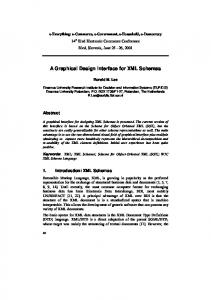
pulse repetition rate of 1 – 100.000 Hz). These parameters are set and executed by the user via Graphical User Interface (GUI) software, our measurements indeed verify proper functioning of both hardware and software. Our output voltage measurements are shown in Fig. 2. They were made by using a WavePro 7300A oscilloscope (LeCroy, USA, 2008) and a high-voltage probe (PPE2KV, LeCroy, USA, 2008).
Relative error [%] 40% 30% 1000V 20% 10%
Relative error [%]
600V 250V
0% -10%
0,5%
Duration [ns] 0,0%
Figure 3. Measured error of the pulse-duration.
-0,5%
-1,0%
Set voltage [V]
Figure 2. Relative error of voltage measurements.
The voltage was measured on the output of a Direct Current – Direct Current (DC-DC) converter (DC-DC in Fig.1) in the range from 260 to 1000 V. The measurement results (see Fig. 2), show that the set voltage (using GUI), displayed voltage (measured internally in the DC-DC converter and displayed in GUI) and measured voltage (using the oscilloscope on the DC-DC converter output) reside all within the range of a 1% difference at the maximum. This rather chaotic error is, however, the consequence of voltage quantization, as the voltage data is sent as an 8-bit parameter from the GUI controller to the Output stage controller and is considered by us as acceptable. The pulse duration was measured, too. The measurements were made in 20 ns steps from a 50% amplitude at the rise time to a 50% amplitude at the fall time using algorithms embedded within the WavePro 7300A oscilloscope (LeCroy, USA, 2008). The results are shown in Fig. 3.
Each pulse-duration value was measured as an average of three samples. As each value was also measured at three different voltages, nine measurements were made altogether for each pulse duration. As according to device specifications, the pulses are generated between 40 and 200 ns, pulse durations were measured within this range, too. They were also measured at 20 ns in order to verify the boundary conditions of the device output stage. As seen in Fig. 3, the deviation of the pulse duration between 40 and 200 ns is within a 10% relative error which we find acceptable. The highest accuracy was achieved with the pulses of the amplitude of 250 V and durations between 40 and 140 ns. The device was first software-calibrated so as to achieve the results shown in Fig. 3. As device calibration is specific to the type of the electrodes used, the pulse parameters (voltage and duration) can change significantly if electrodes used in experiments are different from the ones used at the time of calibration. Therefore, upon each change of the electrodes, the device should be recalibrated to avoid producing inaccurate pulses.
3.3. Software platform A custom software application was designed as the main GUI software. A screenshot of the nanopulse electroporator with GUI is shown in Fig. 4.
A GRAPHICAL USER-INTERFACE CONTROLLER FOR THE BIOMEDICAL HIGH-VOLTAGE SIGNAL GENERATOR
83
need of having the device manually recalibrated each time. The above modifications were not developed and implemented at this stage because they would require an extensive work which would delay the time needed for finishing the device. However, because of the modular structure of the High-Voltage Signal Generator, increasing the complexity of the device by adding additional functionalities is not a problem. Also, many of the hardware and software components of the device can be reused when developing similar new devices. In doing so, the time of development can be shortened and the costs reduced. It is actually a procedure many development departments try to achieve and our device is probably a good example of how to do it. Figure 4. Nanopulse electroporator with the GUI software.
The GUI software is developed in the C# programming language and runs as an embedded application within the Microsoft Windows CE 5.0 .NET operating system. The size of the source code of the GUI software is 97 kB (2348 lines of source code), while the size of the compiled GUI software is 8.246 kB. GUI allows setting all the pulse parameters needed (voltage, duration, number and frequency), and fully operating the device (arming the output stage, starting and stopping pulse generation). Moreover, the pulse parameters can be saved to or be loaded from a file (on an externally attached USB flash disk).
4 CONCLUSION We developed a compact nanopulse electroporator that works reliably and is safe to use. The electroporator is designed in a modular way and the chosen hardware and software assure a good user experience. Our measurements show that the electroporator operates compliably with the imposed specifications as it generates pulses with the appropriate parameters (amplitude, duration, number and frequency). Although the High-voltage Signal Generator is a sophisticated device, there are always new possible ways of improving the user experience. A good improvement would be an additional measurement screen with the time-domain measurements based on the model of oscilloscope user interfaces. Such an implementation would, however, require extensive firmware and hardware upgrades in order to acquire the output voltage in real time, but would actually eliminate the need of an external oscilloscope that is at this moment necessary to measure the generated pulses. Also, there is a possibility of implementing dynamical changing the calibration settings with respect to the electrodes currently used. In this way, different types of electrodes could be frequently changed at no
ACKNOWLEDGEMENTS The development of the device was supported by the Slovenian Research Agency (ARRS), the grant number Z2-2025. The authors thank Matej Kranjc and Jure Koselj for helping them in developing the device.
REFERENCES [1] T. Kotnik, F. Bobanovic, and D. Miklavcic, “Sensitivity of transmembrane voltage induced by applied electric fields - a theoretical analysis,” Bioelectrochemistry and Bioenergetics, vol. 43, no. 2, pp. 285-291, 1997. [2] G. Sersa, D. Miklavcic, M. Cemazar et al., “Electrochemotherapy in treatment of tumours,” EJSO, vol. 34, no. 2, pp. 232-240, 2008. [3] G. Prud'homme, Y. Glinka, A. Khan et al., “Electroporation-enhanced nonviral gene transfer for the prevention or treatment of immunological, endocrine and neoplastic diseases.,” Curr Gene Ther, vol. 6, no. 2, pp. 243-73, 2006. [4] M. Okino, and H. Mohri, “Effects of a High-Voltage Electrical Impulse and an Anticancer Drug on Invivo Growing Tumors,” Japanese Journal of Cancer Research, vol. 78, no. 12, pp. 1319-1321, 1987. [5] L. Mir, N. Morsli, J. Garbay et al., “Electrochemotherapy: a new treatment of solid tumors,” Journal of Experimental & Clinical Cancer Research, vol. 22, no. 4, pp. 145-148, 2003. [6] N. Pavselj, and D. Miklavcic, “Numerical modeling in electroporation-based biomedical applications,” Radiology and Oncology, vol. 42, no. 3, pp. 159-168, 2008. [7] D. Miklavcic, S. Corovic, G. Pucihar et al., “Importance of tumour coverage by sufficiently high local electric field for effective electrochemotherapy,” EJC Supplements, vol. 4, no. 11, pp. 45-51, 2006. [8] A. Macek-Lebar, G. Sersa, S. Kranjc et al., “Optimisation of pulse parameters in vitro for in vivo electrochemotherapy,” Anticancer Res, vol. 22, no. 3, pp. 1731-6, 2002.
84
[9] E. Neumann, M. Schaeferridder, Y. Wang et al., “GeneTransfer Into Mouse Lyoma Cells by Electroporation in High Electric-Fields,” EMBO Journal, pp. 841-845, 1982. [10] M. Kanduser, D. Miklavcic, and M. Pavlin, “Mechanisms involved in gene electrotransfer using high- and lowvoltage pulses - An in vitro study,” Bioelectrochemistry, vol. 74, no. 2, pp. 265-271, 2009. [11] B. Al-Sakere, F. André, C. Bernat et al., “Tumor ablation with irreversible electroporation.,” PLoS One, vol. 2, no. 11, pp. e1135, 2007. [12] S. Beebe, P. Fox, L. Rec et al., “Nanosecond pulsed electric field (nsPEF) effects on cells and tissues: Apoptosis induction and tumor growth inhibition,” IEEE Transactions on Plasma Science, vol. 30, no. 1, pp. 286292, 2002. [13] T. Kotnik, and D. Miklavcic, “Theoretical evaluation of voltage inducement on internal membranes of biological cells exposed to electric fields,” Biophysical Journal, vol. 90, no. 2, pp. 480-491, 2006. [14] K. Schoenbach, B. Hargrave, R. Joshi et al., “Bioelectric effects of intense nanosecond pulses,” IEEE Transactions on Dielectrics and Electrical Insulation, vol. 14, no. 5, pp. 1088-1109, 2007. [15] M. Puc, K. Flisar, S. Reberšek et al., “Electroporator for in vitro cell permeabilization,” Radiology and Oncology, vol. 35, no. 3, pp. 203-207, 2001. [16] U. Hahn, M. Herrmann, F. Leipold et al., “Nanosecond, kilovolt pulse generators,” Pulsed Power Plasma Science, vol. 2, pp. 1575- 1578, 2001. [17] M. Rebersek, M. Kranjc, D. Pavliha et al., “Blumlein Configuration for High-Repetition-Rate Pulse Generation of Variable Duration and Polarity Using Synchronized Switch Control,” IEEE Transactions on Biomedical Engineering, vol. 56, no. 11, pp. 2642-2648, 2009. [18] T. Batista Napotnik, M. Reberšek, T. Kotnik et al., “Electropermeabilization of endocytotic vesicles in B16 F1 mouse melanoma cells,” Medical and Biological Engineering and Computing, vol. 48, pp. 407-413, 2010. [19] D. Pavliha, M. Rebersek, L. Krevs et al., "A Personal Computer as a Universal Controller for Medical-Focused Appliances," 11th Mediterranean Conference on Medical and Biomedical Engineering and Computing 2007, IFMBE Proceedings T. Jarm, P. Kramar and A. Županič, eds., pp. 381-384: Springer Berlin Heidelberg, 2007. [20] A. Aksamovic, Z. Pasic, and F. Imamovic, “Selection of Processors as a Base for Development of Special Purpose Numerical Systems,” in Eurocon 2003, Ljubljana, Slovenia, 2003, pp. 118–121. [21] J. Krasner, Total Cost of Development, Embedded Market Forecasters, Framingham, MA, USA, 2003.
PAVLIHA, REBERŠEK, MIKLAVČIČ
Denis Pavliha received his B.Sc. degree in electrical engineering from the Faculty of Electrical Engineering at the University of Ljubljana, Ljubljana, Slovenia, in 2009. He is currently working towards his Ph.D. degree in electrical engineering at the same faculty where he is employed as a Junior Researcher and Assistant working in the field of Treatment Planning Software for Electrochemotherapy.
Matej Reberšek received his Ph.D. degree in electrical engineering from the University of Ljubljana, Slovenia. He is currently a Research Associate in the Laboratory of Biocybernetics at the same faculty. His current research interests include electroporation, especially design of electroporation devices and investigating biological responses to nanosecond electrical pulses.
Damijan Miklavčič received his Ph.D. degree in electrical engineering from the University of Ljubljana, Slovenia. He is currently a Professor at the same faculty where he is also the Head of the Laboratory of Biocybernetics. He is involved with the field of biomedical engineering. His current research interests include electroporation-assisted drug and gene delivery together with cancer treatment by means of electrochemotherapy, tissue oxygenation and modeling.