{cesar, amt}@ohm.york.ac.uk. Abstract. This paper presents a ... The embryonics project transports these biological mechanisms to the world of electronic ... select a new configuration register from their memory (genome). By selecting a new.
A Hardware Implementation of an Embryonic Architecture Using Virtex® FPGAs. Cesar Ortega and Andy Tyrrell Department of Electronics University of York York, YO10 5DD, UK {cesar, amt}@ohm.york.ac.uk
Abstract. This paper presents a new version of the MUXTREE embryonic cell suitable for implementation in a commercial Virtex® FPGA from Xilinx™. The main characteristic of the new cell is the structure of its memory. It is demonstrated that by implementing the memory as a look-up table, it is possible to synthesise an array of 25 cells in one XCV300 device. A frequency divider is presented as example of the application of embryonic arrays. After simulation, the circuit was downloaded to a Virtex FPGA. Results show that not only it is possible to implement many embryonic cells on one device, but also the reconfiguration strategies allow a level of fault tolerance to be achieved.
1
Introduction
The embryonics project introduces a new family of fault-tolerant field programmable gate arrays (FPGAs) inspired by mechanisms that take place during the embryonic development of multicellular organisms. Embryonics= Embryology + Electronics. Since its introduction, the embryonics project has evolved into different lines of research. [1, 2, 3]. At the University of York the fault tolerance characteristic of embryonic arrays has been investigated for some years now [4, 5, 6]. Embryonics was originally proposed as a new way of designing fault-tolerant FPGAs [7]. Hence, the ultimate goal of the embryonics researcher is to see his/her design integrated in silicon and early versions of the embryonics architecture have been tested using conventional FPGAs [1]. However, individual embryonic cells require large amounts of memory to store their configuration bits (genome). In a 16 × 16 array, approximately 4300 bits of memory per cell are required. Therefore, it becomes difficult to allocate more than one cell in a commercial programmable device. This paper presents a new version of the MUXTREE embryonic architecture that allows the implementation of complete arrays in a commercial FPGA. Section 2 presents a brief introduction to the embryonics project and the evolution of the embryonics architecture studied at the University of York. A new approach to the design of the memory block is presented in section 3. Section 4 presents the design of a frequency divider in a 5×5 embryonic array and its implementation in a Virtex FPGA. Conclusions and proposals for future work are given in section 5.
2
The embryonics project
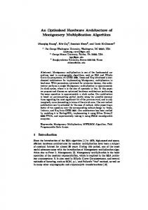
When biological multicellular organisms reproduce, a new individual is formed out of a single cell (the fertilised egg). During the days that follow the time of conception, the egg divides itself by a mechanism called mitosis. Through mitosis two cells with identical genetic material (DNA) are created. The new cells also divide, passing to every offspring a copy of the DNA that corresponds to the individual under development. At some point during their reproduction, cells differentiate into the different tissues that give shape to a complete healthy individual. Differentiation takes place according to “instructions” stored in the DNA (the genome). Different parts of the DNA are interpreted depending on the position of the cell within the embryo. Before differentiation cells are (to a certain extent) able to take over any function within the body because each one possess a complete copy of the genome [8]. The embryonics project transports these biological mechanisms to the world of electronic, programmable arrays. Figure 1 shows the generic architecture of an embryonic array. A detailed description of the cell can be found in [9] N
4 To Neighbour I/O Router
Embryonic Array 4,0
4,1
4,2
4,3
4,4
3,0
3,1
3,2
3,3
3,4
2,0
2,1
2,2
2,3
2,4
1,0
1,1
1,2
1,3
1,4
0,0
0,1
0,2
0,3
0,4
Unique set of co-ordinates
W
E
Memory 17
Processing Element
[3,4]
4
Co-ordinate Generator
3
From Neighbour
5 Diagnosis Logic OK Signal
S
Fig. 1 Generic architecture of an embryonic cell
The configuration register of a cell defines the functionality of its processing element and routing resources. Every cell in an embryonic array stores not only its own configuration register, but also those of its neighbours. When differentiation takes place, cells select a configuration register according to their position within the array. Position is determined by a set of co-ordinates that are calculated from the coordinates of the nearest neighbours. Every embryonic cell performs self-checking by means of built-in self-test (BIST) logic. A detailed description of the self-testing mechanisms can be found in [7]. When a failure is detected, the faulty cell issues a status signal that propagates to the nearest neighbours. In response, some cells become transparent to the calculation of co-ordinates and consequently, they are logically eliminated from the array. Cells are eliminated according to the reconfiguration mechanism in use, e.g. cell elimination, row-elimination. The remaining cells recalculate their co-ordinates and
select a new configuration register from their memory (genome). By selecting a new configuration register every cell performs a new function. Provided the amount of spare cells is sufficient to replace all the failing cells, the overall function of the original array is preserved [9, 1]. 2.1
The MUXTREE embryonic cell
The MUXTREE is a variant of the generic embryonic cell where the processing element is a multiplexer, (henceforth referred to as the main multiplexer). The architecture of the generic MUXTREE cell requires a memory with capacity to store the configuration registers of all the cells in the array. Although this approach maps directly the concept of genome into the embryonic architecture, it is highly inefficient in the use of resources. In practice, a cell can only replace neighbouring faulty cells because of its limited connectivity. Therefore, there is little point in storing in a cell the configuration registers of cells that it will never replace. A detailed description of the generic MUXTREE architecture can be found in [9]. The fault tolerance characteristic of MUXTREE arrays has been the object of various studies at the Department of Electronics, University of York [4, 5, 6]. Considering that simplicity (small size) implies better reliability, the problem of memory size has been addressed following various strategies. To reduce the size of the memory inside each MUXTREE cell, a chromosomic approach was proposed in [5]. In an array performing row-elimination, faulty cells are substituted exclusively by their north neighbours. Hence, the chromosomic approach requires each cell to store only the configuration registers of all the cells in the corresponding column. Consequently, every cell in an array of size n×n has to store only (n+1) configuration registers, instead of the (n2+1) required in the original proposal. The extra configuration register sets the transparent state that cells enter when they are eliminated.
3
A new design of the MUXTREE’s memory element
As mentioned, the set of all the configuration registers in an embryonic array is called the genome. Once the genome of a particular application has been defined, it does not change throughout the useful life of the array. This implies that once defined, the memory behaves as a ROM or Look-Up Table (LUT); i.e. every set of co-ordinates (address) is associated to only one configuration word (data). This characteristic is exploited in the new approach described here to solve the problem of memory complexity. Some modern FPGAs, like the Xilinx’ Virtex family, use LUTs to implement logic functions [10]. Powerful synthesis tools like the Xilinx’ Foundation® suite, aid the designers to efficiently map their applications onto the FPGAs. In order to use as few FPGA resources as possible, synthesis tools analyse designs and minimise the logic needed to implement them. It is possible to simplify the memory on every MUXTREE cell by defining a LUT that represent the genome and then allowing the synthesiser optimise it. Since not all
the configuration bits are used in all the cells, it is possible for the synthesiser to literally eliminate bits of memory. For example, cells that are not used must be programmed to a default value, resulting in many cells having the same genome. The synthesiser is able to detect configuration bits that will not change under any circumstance during the operation of the embryonic array. To save FPGA resources, these bits are tied to a logic value instead of generate them using logic. Such optimisation techniques generate architectures suitable for implementation in an FPGA. A simple example will now be discussed, followed by its implementation.
4
Example
To investigate the efficiency of the new approach for designing the MUXTREE’s genome memory, the design of a programmable frequency divider is presented. Figure 2 shows the circuit’s block diagram. This circuit is an improved version of the frequency divider presented in [5]. It consists of a 3-bit selector that latches either a constant n (the division factor), or the next state of a 3-bit down counter. The selector is controlled by the output of a zero detector. The circuit generates a 1-cycle lowpulse when the down counter reaches the 000 state. The output of the zero-detector will have a frequency lower than F by a factor proportional to n. Down-counter Next state
Zero-detector CBA
clk F
sel Selector
3
1
F/n
0 n
C + B+ A +
DS2-DS0
Frequency divider
Fig. 2 Programmable frequency divider
Figure 3 shows the implementation of circuit in figure 2 using multiplexers. DS2 Z C+
0 S 3 1
C
DS1 Z B+
0 S 2 1
B
DS0 Z A+
0 S 1 1
A
F
1 C 0
0 S 6 1
B C
0 S 7 1
A+ B A
0 S 5 1
A C
0 S 8 1
C+
F
F
1 A 0
0 S 4 1
B+
B C 1
0 S 9 1
A 1
Fig. 3 Frequency divider implemented using multiplexers
0 S 10 1
Z
In figure 3, every multiplexer corresponds to a node in the corresponding Ordered Binary Decision Diagram (OBDD) [3]. A, B and C are the outputs of the 3-bit down counter, C being the most significant bit. Multiplexers 1, 2 and 3 update their outputs on the rising edge of F; they implement the selector block. DS2, DS1 and DS0 are used to set the value of n. Figure 4 shows the circuits in figure 3 mapped into an embryonic array. The numbers on each cell correspond with the numbers assigned to the multiplexers. Cells labelled S are spare cells. Cells labelled R are routing cells. Routing cells are needed to propagate information between non-neighbouring cells. Z
Z
F
Z
S
S
S
S
S
S
S
S
S
S
R
10
8
R
R
S
S
S
S
S
R
10
8
R
R
R
5
9
7
6
R
10
8
R
R
R
5
9
7
6
R
5
9
7
6
4
1
2
3
R
4
1
2
3
R
4
1 DS0
2
3
DS1
DS2
R
F
F DS0
a) With no faulty cells
DS1
DS2
DS0
b) With one faulty cell
DS1
DS2
c) With two faulty cells
Fig. 4 Frequency divider implemented in embryonic array
At the present stage of the project, the mapping {logic equations}→{OBDDs}→ {Multiplexers}→{Embryonic array}, is done manually. An automated mechanism will be needed to implement applications that require a large number of multiplexers. Figure 5 shows the content of the configuration register that configures each cell. 16 15 14 13
12 11 10
9
8
7
6
5
4
3
2
1
0
W1:0 E1:0. S1:0. N1:0. R2:0. REG L2:0 EBUS1:0
Fig. 5 Content of the configuration register
• EBUS1:0- Selects the selection input for the main multiplexer in every cell. • L2:0, R2:0- Select the left (L) and right (R) inputs of the main multiplexer. For each input, one of eight possible signals is chosen. • REG- If this bit is 1, the output of the cell becomes the registered output of the main multiplexer. If it is 0, the direct non-registered output is selected. • N1:0, E1:0, W1:0, S1:0- These bit-pairs control the outputs of the I/O router.
Figure 6 shows the VHDL code of a look-up table with eight inputs (LUT-8) containing the genome that implements the frequency divider. Note that most of the 64 combinations presented in the inputs generate the code for the transparent configuration (0A200h). The synthesiser eliminates all the redundant bits, resulting in a very compact LUT that performs the function of the genome memory. Spare cells have the same configuration as transparent and routing cells; i.e. they just propagate signals across them. library IEEE; use IEEE.std_logic_1164.all; entity Mem_freq_div is port (ok: in STD_LOGIC; -- OK status signal xy: in STD_LOGIC_VECTOR (5 downto 0); -- Co-ordinates conf: out STD_LOGIC_VECTOR (16 downto 0)); -- Genes end Mem_freq_div; architecture Mem_freq_div_arch of Mem_freq_div is type REG is array (16 downto 0) of bit; begin process(ok,xy) begin if (ok = ’0’) then conf conf conf conf conf conf conf conf conf conf conf conf conf