Parallel hardware implementation of a broad class of spiking neurons using serial arithmetic Benjamin Schrauwen∗ Jan Van Campenhout ELIS, Ghent University, Belgium
[email protected]
Abstract. Current digital, directly mapped implementations of spiking neural networks use serial processing and parallel arithmetic. On a standard CPU, this might be the good choice, but when using a Field Programmable Gate Array (FPGA), other implementation architectures are possible. This work present a hardware implementation of a broad class of integrate and fire spiking neurons with synapse models using parallel processing and serial arithmetic. This results in very fast and compact implementations of spiking neurons on FPGA.
1
Introduction
Compact, directly mapped hardware implementations of spiking neurons have previously [3, 4] been implemented using serial processing of the synapses and decay operations, but using parallel arithmetic (i.e., operating on words, as normal CPUs do). When implementing this on a standard CPU architecture, this might be a good choice, but when using FPGAs (like all these implementations do), other architectures are possible and might be better suited. In this work we present a hardware implementation of a broad class of Leaky Integrate and Fire (LIF) neurons with synapse models, using parallel processing of the synapses and serial arithmetic. Pipelining is used to optimize hardware usage. A directly mapped implementation using pipelining was already presented in [6]. There however, only a single processing element was used which simulated a very simple neuron model using parallel arithmetic. Because we are interested in compact implementations of rather small networks (< 1000 neurons) of spiking neurons we opt to use time step based simulation instead of event based simulation1 . Applications of such ‘small’ networks include autonomous robot control, LSM based speech recognition [5], embedded learning signal processors, ... Event based simulation does allow very large networks of spiking neurons to be simulated approximately 10 times faster (when we assume an average neuron activity of 1%) than time step based simulation, but they require a lot of hardware resources (multiple FPGA chips [2]), and currently do not allow parallel processing. Event based systems also do not guarantee strict real-time behaviour (they could, but then they are an order of a magnitude slower), which in many applications is mandatory. ∗ This
research is partially funded by FWO Flanders project G.0317.05. for such ‘small’ networks include autonomous robot control [3], speech recognition [5], embedded learning signal processors, ... 1 Applications
t
t+1
input 1
t+2
t+3
t+4
t+5
synapse model
input 2
S input 3 serial dendrite adder
synapse input 4
S
M
output
input 5 membrane
input 6 control signals control pipeline
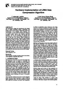
Fig. 1: Overview of an example neuron architecture
2
Spiking neuron model
The hardware architecture we present can implement a broad class of spiking neurons [1] with a LIF membrane model and several different synapse types per neuron. Absolute refractoriness, or the temporary insensitivity of the neuron after it has fired, is also supported. All synapses of the same type (and same time constant) are grouped in a so called synapse model. This is allowed by the linear nature of the synapses. The supported synapse models are exponential or Dirac delta (no synapse model). Note that two exponential synapse models could be placed one after another to construct for example alpha-type synapse responses. Due to the modular structure of the neuron model, more complex dynamic synapses with facilitation and depression can also be implemented as long as they can be modelled by a combination of exponential filtering operations.
3
Implementation
An overview of the general neuron architecture is given in Figure 1. Each of the inputs is fed to a synapse block, these will serially shift out (least significant bit first) their weights in case of an incoming spike. Two synapse outputs are joined together by a dendrite adder which serially adds the two streams by adding bit by bit, least significant bit first, and remembring the carry. A synapse model block implements exponentially decaying synapse models by leaky-integrating the input. The membrane block implements a LIF membrane using serial arithmetic. Because the implementation is pipelined (flip-flops are added after each processing stage to improve throughput) a delay line for the control signals is needed. The processing is split up in several parts which is depicted in Figure 2. First an idle state is needed to pre-set all internal signals. Next, several integrate states are issued which command the synapses to serially transmit their weights, and the synapse models and membrane to integrate them. The number of clock
decay idle
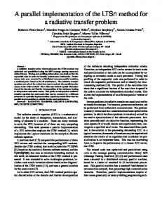
clk integrate decay state_end tap extend
integrate tap 1 tap 2 1 0 00000000 11111111 00000000 11111111 00000000 11111111 0 1 0 1 0 1 00000000 11111111 00000000 11111111 00000000 11111111 0 0 011111111 1 0000000011111111 0000000011111111 000000001 01 1 0 1
0
1
time
Fig. 2: This diagram shows the timing structure cycles used by the integrate state is equal to the internal bit precision B. Then, the decay state will serially implement exponential decay inside the synapse models and the membrane using one or more taps (shifted versions of the internal potential) which are subtracted from the original potential. Each tap takes B clock cycles. Figure 2 shows the detailed control sequence generated by the controller for neurons with 12 bits internal precision and two taps. Note that only one controller is needed if the neurons have similar architectures. The integrate and decay signals represent the integrate and decay state respectively. The state end signal is high at the end of the integrate state and each of the taps of the decay state. It is used for various maintenance tasks that need to happen at the end of a integrate/decay state like checking the saturation and threshold, setting the carry, ... During the decay state, the tap signals differentiates between the different taps. The extend signal is used to sign extend the shifted version of the potentials. This is done by remembering the sign bit of the potential at the correct time which depend on the actual tap value. Note that for the membrane and each of the synapse models separate extend signals are used because they all can have different tap values (not shown in the figure). The details of the synapse are shown in Figure 3a. It consists of a shift register that is enabled by the integrate control signal. The output is enabled when a spike is present. Notice that the output does not hold a flip-flop; so this block does not increase the pipeline depth as is shown in Figure 12 . A dendrite adder, shown in Figure 3b, implements a serial addition. This is done by a single fulladder with delayed carry. After the integrate state, the carry flip-flop is reset to zero. We implemented a binary adder tree. The width/breadth could be increased leading to a shallower tree and less pipeline stages, but implementing this is only advised for FPGAs that have LUTs with more than 4 inputs (like the Altera Stratix II). The internal structure of the membrane block is depicted in Figure 3d. The 2 On Xilinx FPGAs this shift register can be very efficiently implemented using the SRL16E mode of lookup tables (LUTs, the basic building blocks of FPGAs) which allow each LUT to be transformed into a 16 bit shift register. On Altera FPGAs 18 synapses could share one M512 memory block (32x18 topology) which can be put in FIFO mode.
state_end
input
1 0 0
output integrate
CE
stored weight
shift correction
decay
0 1
clk integrate
output
carry
(a) synapse carry
input
input 1
1 0
CE
extend
output input 2
integrate
1 0
1 0
enable
sign extend
decay integrate
0
(b) dendrite adder
(c) synapse model
state_end saturate 0 1
0 1
CE
1
0 1
CE
1
0
0 1
CE
CE
integrate
0
decay state_end
shift correction
1 0 0
integrate 0 1
decay
tap
CE
carry input 1 0 1 0
tap
integrate CE
refractory
extend
CE
integrate state_end CE
saturate
fire
output
(d) membrane
Fig. 3: Internal structure of different building blocks
Nr LUTs FFs Synapse NI 2 0 Dendrite adder N I 2 2 Synapse model N S ⌈log2 T ⌉ + 6 B+2 Membrane N B + ⌈log2 T ⌉ + 15 B+4 Controller 1 5(⌈log2 B⌉ + 1) (S + 1) + ⌈log2 T ⌉ + ⌈log2 B⌉ + 6 Table 1: Size results main part is the internal shift register holding the membrane potential. In the integrate state the input is serially added to the membrane potential if the neuron is not in its refractory period or firing. At the last clock cycle of the integrate state three blocks check if the membrane potential is: bigger than 2SAT , then fire; or bigger than 2SAT and smaller than −2SAT , then reset the membrane potential to its reset value (this implements reset after fire and negative saturation); or smaller than 2REF R , then keep the neuron in refractory. During the decay state, one or more shifted and negated versions of the membrane potential are added. Prior to each tap, the carry is set to 1 if negative. It is also set to one if all the lower bits of the potential are equal to 1. This trick makes sure the potential decays all the way to zero and won’t get stuck at a higher value. The extend signal enables sign extension during the last clock cycles of the addition. In the idle state the carry flip-flop is reset3 . Figure 3c depicts the internal working of an exponentially decaying synapse model. Notice the similarities with the membrane block. A synapse model block is actually a membrane block without reset, threshold detection and refractoriness. The output is just the buffered result from the serial accumulation of the input value and the internal potential. The current implementation uses direct interconnection between the neurons; but other schemes like a bus or a memory based interconnection are possible.We also use fixed weights, meaning that the weights are predetermined at the time of synthesis. Changing these weights afterwards is possible by re-synthesizing the design or via dynamic reconfiguration (reprogramming parts of the FPGA while it is operational), also used in [4]. A slightly different version of the design was implemented where on-line changing of the weights is possible by placing all the weight’s shift registers in a long scan chain. This can be implemented with very few extra resources. If double buffering4 is used, the design can continue operating while the weights are being shifted in. Other parameters like time constants, thresholds and reset values can only be redefined by re-synthesis or dynamic reconfiguration. 3 The implementation shown in Figure 3d has internal precision B = 13, number of taps T = 2, saturation bit range SAT = 9, refractory bit range REF R = 8, first tap position T AP 1 = 3, second tap position T AP 2 = 4. 4 All weight memory is doubled. One copy will be used during operation while the other can be used to write data into. After the write operation is ready, both memories are switched.
Table 1 shows the synthesis results with respect to the important parameters: N neurons each with I inputs, S synapse models, T taps and B bits of internal resolution. The number of clock cycles needed to process one neuron time step is approximately ⌈log2 I⌉ + B(1 + T ) + 1. On a cheap and small Xilinx Spartan 3 FPGA device (XC3S200), using neurons with 12 bit resolution, one synapse model and 10 inputs, we can implement approximately 56 neurons clocked at 120 Mhz, resulting in 2930 times real-neuron-time5 speed. On a state-of-theart Virtex 4 FPGA (XC4VLX100) we can implement 1400 neurons running at approximately 5860 time real-neuron-time speed (estimate). Compared to the hardware models presented in [3, 4] our models do take up more space, but are much faster (it is difficult to compare numerical values because they used an older FPGA technology). We also support much more complex neuron models.
4
Conclusions and future work
This work presents a directly mapped, parallel implementation using serial arithmetic of a broad class of LIF spiking neurons with synapse models. As a result we are able to implement 1400 neurons running at 5860 times real-neuron-time on state-of-the-art FPGAs. Currently no weight adaptation was implemented. For future work we plan to incorporate Spike Timing Dependant Plasticity (unsupervised learning) and an easy interface to an accompanying CPU which can then be used to perform supervised learning. We also plan to use this hardware to implement a speech recognition system based on the Liquid State Machine [5] which does not need its weights to be trained.
References [1] W. Gerstner and W. M. Kistler. Spiking Neuron Models. Cambridge University Press, 2002. [2] H. Hellmich, M. Geike, P. Griep, P. Mahr, M. Rafanelli, and H. Klar. Emulation engine for spiking neurons and adaptive synaptic weights. In Proc. of IJCNN, pages 3261–3266, 2005. [3] D. Roggen, S. Hofmann, Y. Thoma, and D. Floreano. Hardware spiking neural network with run-time reconfigurable connectivity in an autonomous robot. In NASA/DoD Conf. on Evolvable Hardware, pages 189–198, 2003. [4] A. Upegui, C. A. Pe˜ na Reyes, and E. Sanchez. An FPGA platform for on-line topology exploration of spiking neural networks. Microprocessors and Microsystems, 29:211–223, 2005. [5] D. Verstraeten, B. Schrauwen, D. Stroobandt, and J. Van Campenhout. Isolated word recognition with the liquid state machine: a case study. Information Processing Letters, 95(6):521–528, 2005. [6] J. Waldemark, M. Millberg, T. Lindblad, K. Waldemark, and V. Becanovic. Implementation of a pulse coupled neural network in FPGA. International Journal of Neural Systems, 10(3):171–177, 2000. 5 The number of times the hardware can run faster than real-time assuming a simulation time step of 1 ms.