9th Annual Conference of the International FES Society September 2004 – Bournemouth, UK
A highly parallelizable signal conditioning module dedicated to cortical implantable monitoring devices Gosselin B, Sawan M PolySTIM Neurotechnologies Laboratory, Electrical Engineering Department, Ecole Polytechnique de Montreal, P.O.Box 6079, Station Centre-Ville, Montreal, (Quebec), Canada, H3C 3A7 Email:
[email protected] Website: www.polystim.polymtl.ca
Abstract We present a low-power analog signal conditioning system intended for cortical data recording. Using Chopper modulation enhances recording quality and decreases integrated devices sizes, making this implementation suitable for highly parallelized monitoring systems. Low-power design techniques allows the proposed conditioning module to acquire neural signals from a few Hz to 7kHz while meeting power consumption and input noise requirements. The proposed signals acquisition module, implemented in 0.18µm CMOS process, achieves power consumption below 20µW and occupies only 0.0705 mm2 of chip area.
1
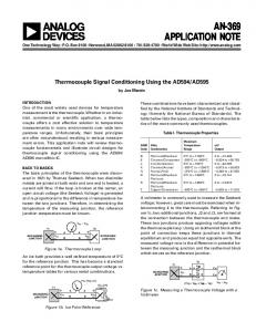
cells in the visual cortex areas, as depicted on figure 1. The conditioning path includes a preamplifier, filters and a gain amplifier.
Figure 1: Implantable recording devices for simultaneous monitoring in several cortex areas.
Introduction
Neurophysiology has explored multiunit recording since a few years in accordance with neural assemblies coding assumptions. Researchers have combined electronic circuits with micromachined multielectrodes arrays to increase the recording quality, the spatial resolution of measurements and the experimental apparatus stability. The needs for new experimentations and novel prosthetic devices, as Brain Computer Interface (BCI), is now carrying out researches towards the implementation of more recording channels, leading to more power efficient and smaller circuits. However, recording quality is of major concerns for neural recording and must not be neglected. Most neural recording systems are composed of a single high gain amplifier prior to analog-to-digital (A/D) conversion. This approach may be too sensitive to electromagnetic interference (EMI) and may have poor signal-to-noise ratio (SNR). We present a complete analog conditioning module suitable for highly parallel integration into an implantable multichannel system, which could be used for simultaneous monitoring of several
2
Methods
CMOS process is well suited for implantable medical instrumentation devices such as cortex monitoring systems because of high input impedance of MOSFETs and their low power consumption. However, CMOS suffer from higher inherent noise than other processes as bipolar. Thermal noise and low frequency noise are dominant noise sources in MOS transistors. The 1/f noise in transistors is mostly related to their sizes. Thus, area consuming devices must be used to implement the input stage of low-noise amplifiers. Consequently, this imposes serious limits on the number of channels that could be integrated for recording. The Thermal noise must also be carefully considered since higher DC bias currents must be used to keep it low, draining an important amount of power. The trade off between noise, power consumption and circuits sizes is efficiently addressed in this design by usage of Chopper modulation [1]. This method is used to reduce low frequency noise inherent to CMOS devices and decrease the circuits size, as it will be shown later.
9th Annual Conference of the International FES Society September 2004 – Bournemouth, UK
Figure 1: Parallelized low-power chopper modulated conditioning modules.
3
Chopper devices
modulated
conditioning
Figure 2 shows a block diagram of the Chopper modulated conditioning module. Fig. 3 presents the output signal of each block when a low amplitude sine wave is conditioned by the module. The Chopper frequency (fchop) is set to 20kHz. A More detailed description of each block can be found in [1].
serial bus connection. The Universal Serial Bus (USB) is efficient and convenient for serial data transfer. A transfer rate of 1Mbytes/s is allowed with USB1.0 and may be extend to more than 20Mbytes/s with USB2.0. USB also provides the whole acquisition system to be portable. USB1.0 allows 32 channels with 30kHz sampling rate per port.
Figure 3: A multichannel cortical monitoring system. Figure 2: Chopper modulation: detailed signals.
4
Highly devices
parallelized
monitoring
A complete multichannel monitoring device is depicted on figure 4. The performances reached by the conditioning module allow 32 channels devices, consuming less than 1mW and stand within 2.5mm2 of chip area. The neural signals are transferred from the implantable device using percutaneous hard wired connections or Radio Frequency (RF). Additional circuits as voltage rectifier and regulators are required for RF energy transfer. Bidirectional transmission is desirable for system configuration, to set analog parameters, as gain or bandwidth, and digital parameters, as transfer rate, sampling frequency or channel activation/deactivation. A serial data transfer link is used to decrease the number of percutaneous wires, requiring fast
5
Acquisition software
Custom software is used for data storage management and visualisation. Data analysis and signal processing methods may be embedded in the software or done with dedicated Matlab toolboxes such as presented in [2]. Signal processing needed prior to analysis may involve tasks such as spikes sorting and denoising. Its goal is to construct reliable spikes trains for further analysis. Also, the software must manage bidirectional data transfer. Multiport data transfer is supported by the software. The transferred data may then be distributed over a few USB ports to increase the throughput. The software under development allow data visualization, data reconstruction and data storage. The neural data can be saved to ASCII format or to Matlab format for further processing and analysis. Fig. 5 shows the graphical user interface of the implemented software.
9th Annual Conference of the International FES Society September 2004 – Bournemouth, UK Table 1. Preamplifier characteristics DC Gain 42.1 dB Bandwidth 102kHz Power consumption 18uW Table 2. Bandpass filter characteristics Center frequency 20kHz Power consumption 288nW Table 3. Bandpass filter characteristics Cutoff frequency 7kHz Power consumption 288nW
Table 4. Gain amplifier Parameters Values DC gain 40.2 dB Bandwidth 30.2kHz Power consumption 730nW
Table 5. Overall system Summary Power consumption