Abstract â In this paper we propose a new approach of signal conditioning circuits. The circuit is able to handle both electrochemical and bioluminescent ...
2010 IEEE 26-th Convention of Electrical and Electronics Engineers in Israel
VLSI Universal Signal Conditioning Circuit for Electrochemical and Bioluminescent Sensors David-George Cristea
Yosi Shacham-Diamand
Politehnica University Timisoara
Tel Aviv University
Virgil Tiponut Politehnica University Timisoara
Hadar Ben-Yoav
Mihai-Emanuel Basch
Zoltan Haraszy
Tel Aviv University
Politehnica University Timisoara
Politehnica University Timisoara
Abstract – In this paper we propose a new approach of signal conditioning circuits. The circuit is able to handle both electrochemical and bioluminescent sensors, mainly electrochemical sensors. The integrated circuit will convert electrical signal into impulses, making the frequency the carrier of the information. In this way we avoid amplifying stages, reducing circuit complexity and area on chip. The biggest obstacles that we manage to overcome ware the major difference between the currents provided by the sensors and the sense of the currents. We still need to build an interface capable to work not only with one sensor but with 6X6 or 8X8 sensors. Keywords – integrated signal conditioning circuit, bioluminescent sensors, electrochemical sensors, universal signal conditioning circuit
I. INTRODUCTION In this paper we describe a circuit that is able to work with both electrochemical and bioluminescent sensors. The main problem of these sensors is that one absorbs current from the circuit and one injects current into the circuit. We manage to resolve this problem without using two sets of circuits. Another problem is that the bioluminescent and electrochemical sensors work with different range of currents.
systems derived from them it is named bioluminescence (BL). The analyte concentration can be determined by measuring the CL emission intensity, because it is a function of the concentration of the chemical species involved in the CL reaction. The CL method is a superior detection method for microfluidic systems due to the simple instrumentation and high sensitivity involved. The optical system used requires no external light source, which not only simplifies the instrumentation but also reduces noise, which in turn lowers the detection limit [2]. III. CIRCUIT BLOCK DIAGRAM The circuit we propose is based on the concept presented in [3] and [4]. The main idea is to eliminate the amplifying stages and to convert the small currents, either electrochemical or bioluminescent, but mainly electrochemical currents into time, making the frequency the carrier of the information. Eliminating amplifying stages we reduce area on chip, lowering the cost and complexity of the chip in the same time.
II. ELECTROCHEMICAL AND BIOLUMINESCENT SENSORS Integration of various chemical devices and complex operations onto a micro-chip, which is often referred to as a micro-total analysis system (µ-TAS) or “lab on a chip”, is currently generating major interest due to the promising characteristics of such systems. Over the last few years, the dimensions of these systems have decreased, resulting in the ability to accommodate biological sensors on solid-state platforms with micron scale features. There are few methods to detect the generated signal from the microbial cells, e.g. optical, electrochemical, electrical and mechanical. Electrochemical biosensors are based on a bio-interaction process, where electrochemical species are consumed or generated producing a measurable electrochemical signal. Electrochemical measurements detect only the electrical properties of the analyte species undergoing redox reactions; therefore, they are limited to sensing electro-active species. Electrochemical detection usually uses amperometry, potentiometry or conductometry [1]. Chemiluminescence (CL) is the generation of light due to the release of energy during a chemical reaction. When this emission originates from living organisms or from chemical
978-1-4244-8682-3/10/$26.00 ©2010 IEEE
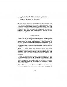
Fig. 1. Block diagram of the proposed circuit. At the entrance of the circuit we have, Fig.1, a switch that commute between the electrochemical sensor and the bioluminescent sensor, point A and B in the design. First, we assume that point A is connected. In this case, the multiplexor MUX will send at the entrance of the operational transducer OTA 0.5 V and at one entrance of the comparator COMP 2.4
000249
V. The current from the sensor will start to charge the 1 pF capacitor, until the voltage will reach 2.4 V. When this value is obtained, the comparator will send a signal to the ONESHOT circuit. The role of this circuit is to amplify the signal enough to reset the two keys of the circuit discharging the capacitor to 0.5 V and bringing 2.4 V at the entrance of the comparator COMP. The same impulse will be send to the D Flip-Flop circuit that transforms the impulses into the OUT signal of the design. More toxic agent into the water will be translated in more light, a bigger input current which will charge the capacitor faster, so the comparator will fire faster to the One-Shot circuit, which will reset faster the circuit so the frequency of the signal will increase proportionally with the concentration of pollutants. In the other case, the entrance of the circuit is on point B, at the exit of the electrochemical sensor. In this case, the OTA integrates the signal downwards, from 2.4V to 0.5 V. The MUX will provide 2.4 V to the entrance of the OTA, charging the capacitor, and, 0.5 V to the entrance of comparator COMP. The current from electrochemical sensor will start to discharge the capacitor until it will reach 0.5 V. In this moment, comparator will send a signal to ONE SHOT. This signal, which resets the keys, is also the output signal of the circuit. Also, in this case, the frequency is proportional with the pollutants concentration.
three electrode electrochemical micro-chamber. a) Ag electroplating (Standard Ag nitrate bath) at a rate of 0.8 µm/min; b) Anodization of the Ag in a bath containing chlorine ions. The presence of toxicants induces a cascade of biological reactions in the genetically engineered bacteria, producing an increased concentration of the enzymatic bio-reporter alkaline phosphatase. This enzyme catalyzes the reaction converting the substrate para-aminophenyl phosphate (pAPP) to the electro-active species para-aminophenol (pAP).. Therefore, by using an appropriate electrochemical transducing system, the generated electrochemical bio-signal can be detected. Fig. 6 presents chrono-amperometric results of the response of E. coli bacteria in the presence and the absence of the model toxicant NA. The response of the bacteria in the presence of NA showed an increasing electrochemical current after pAPP was added.
A
IV. SIMULATIONS AND RESULTS The proposed electrical circuit was designed for the electrochemical micro-chip whole-cell biosensor presented by Ben-Yoav and colleagues [1].This bio-chip comprised of four cylindrical electrochemical 50 µm deep micro-chambers with different radii: 1 mm, 0.5 mm, 0.25 mm, and 0.125 mm. The corresponding volumes were 157 nl, 39 nl, 9.8 nl, and 2.5 nl. Each chamber contains three electrodes: working electrode (WE), counter electrode (CE) and reference electrode (RE). The electrodes are made of thin evaporated gold (300 nm)/Cr (15 nm). The open reference electrode was coated with Ag/AgCl layers (Fig. 2B). The Ag/AgCl open reference electrode was manufactured by a two-step electrochemical process:
B
A
Ag/AgCl Reference electrode Au Working electrode Au Counter electrode Micro-chamber wall
1mm
Fig. 2. (A) Si micro-chip with 4 differentially sized C electrochemical micro-chambers. (B) Inside view of a single
B
Fig. 3. Chrono-amperometric results of E. coli cells in the presence of pAPP following with either an induction period with nalidixic acid (A) or without an induction (B). As seen in Fig. 3, there is an important difference between the signal generated by bacteria in the presence of the pollutants and the signal generated in the absence of the pollutants. This will be translated by the circuit we proposed here in a lower frequency for the absence of pollutants and in a much higher frequency for the presence of the pollutants. In the future, because of the fast development of the biotechnology and biochemistry, the measurements and analysis will be made faster, the circuit being capable to detect changes in the current value much lower than biotechnology is able to analyze today. The goal is to integrate as many components of the circuit as possible, to make it reusable, despite the disposable electrochemical sensors present on the market today.
Part B: PDMS microfluidic chip ~ 1 cm thick
Micro channel Whole cell assay
Sample in Polymer - ~50 µm
000250 Au / Cr
Au/Cr - ~ 215 nm
Fig. 4.Electronic design of the circuit. Due to the fact that bioluminescent sensor provide at the output current in picoAmper range and the electrochemical sensor work with much smaller currents, the simulations took a long time. Also the sense of the current was a challenge that we manage to overcome without using two sets of circuits.
the design is not influenced by this problem. Anyhow we will try to resolve this by dimensioning more of the comparator’s transistors. The circuit design was made in 0.25um Generic technology. The circuit, we propose, offers the advantage of being able to work with both electrochemical and bioluminescent sensors without using two separate circuits. Due to the duality of this kind of sensors, being able to use them with the same signal conditioning circuit is a real advantage in practice.
Fig. 5. Simulation results for bioluminescent sensor. The signal at the entrance of the circuit in the bioluminescent sensor case was 0.1 µA signal. The signals in Fig.5, down-up are: Out signal of OTA, Out signal of COMP, Out signal of One Shot and Out signal for the all design. In Fig.6, we present the result for the electrochemical sensor simulation. In this case, at the entrance of the circuit we had a 0.1 pA continuous signal. The order of the signal is the same as in Fig. 5. The problem in this case is that the integration of the current does not start at 0.5 V as it should, but at 0.65 V due to the offset of the two keys, the two simple transistors in the circuit. In the near future, we will overcome this problem by replacing the two transistors with more complex circuits. Because of the very small current we have at the input of the circuit, the signal at the output of comparator COMP, in this case is not very big, but it is big enough to trigger the One Shot circuit, so the functionality of
Fig. 6. Simulation results for the electrochemical sensor case. V. FUTURE WORK The proposed electrical circuit is planned to be applied with real biosensor assays where the electrochemical current is generated by bacterial whole-cells in response to the presence of toxins in water. By successfully applying the circuit, the signal can be significantly improved resulting in sensitive with short time response device. Furthermore, by improving the signal intensity and signal-to-noise ratio, lower volumes of biological assays can be applied helping to miniaturize the micro-chip dimensions and increasing the amount of assays
000251
analyzed on one chip. Next, we will try to eliminate the offset of the keys by replacing them with more complex circuits, maintaining in the same time an acceptable low complexity of the design, with as few as possible components. We also want to design at the entrance of the circuit a kind of multiplexor, so the circuit will be able to handle more than one sensor at a time. The goal is to make circuit handle matrix of 6x6 or 8x8 combined sensors, both electrochemical and bioluminescent sensors. We also will remake the dimensioning of the transistors so we will obtain more clear signals at the exit of the comparator. Another goal of our future research is to enlarge the difference between the smallest current that can be detected and the maximum current that can be transformed by the circuit. The circuit will be fully integrated on chip, so all the measurements, and as much as possible the analysis and interpretation of results, will be made in field. ACKNOWLEDGMENT This work was partially supported by the strategic grant POSDRU 6/1.5/S/13, Project ID6998 (2008), co-financed by the European Social Fund – Investing in People, within the Sectorial Operational Program Human Resources Development 2007-2013. This work was partially supported by the strategic grant POSDRU/88/1.5/S/50783, Project ID50783 (2009), cofinanced by the European Social Fund – Investing in People, within the Sectorial Operational Program Human Resources Development 2007-2013. REFERENCES [1]
[2]
[3]
[4]
Hadar Ben-Yoav, Alva Biran, Rami Pedahzur, Shimshon Belkin, Sebastian Buchinger, Georg Reifferscheid, Yosi Shacham-Diamand, “A whole cell electrochemical biosensor for water genotoxicity biodetection ”Electrochimica. Acta, 2009,electacta.2009. Changqing Yi, Qi Zhang, Cheuk-Wing Li Jun Yang, Jianlong Zhao, Mengsu Yang, ”Optical and electrochemical detection techniques for cell-based microfluidic systems”, Analytical and Bioanalytical Chemistry, Volume 384, Number 6,1259-1268, 2006. Syed K. Islam, Rajagopal Vijayaraghavan, Mo Zhang, Steven Ripp, Sam D. Caylor, Brandon Weathers, Scott Moser, Stephen Terry, Benjamin J. Blalock, Gary S. Sayler, “Integrated Circuit Biosensors Using Living Whole-Cell Bioreporters”, IEEE Transactions on Circuits and Systems - I: Regular Papers, Vol. 54, No. 1, Jan. 2007. Harpreet S. Narula , John G. Harris, “VLSI potentiostat for amperometric measurements for electrolytic reactions”,2004. ISCAS '04, Proceedings of the International Symposium on Circuits and Systems, Vol.: 1, pp: I - 457-60, 23-26 May 2004.
000252