IEEE Transactions on Consumer Electronics, Vol. 53, No. 2, MAY 2007
732
A Joint Motion & Disparity Motion Estimation Technique for 3D Integral Video Compression Using Evolutionary Strategy S. Adedoyin, W.A.C. Fernando, A.Aggoun Abstract - 3D imaging techniques have the potential to establish a future mass-market in the fields of entertainment and communications. Integral imaging, which can capture true 3D color images with only one camera, has been seen as the right technology to offer stress-free viewing to audiences of more than one person. Just like any digital video, 3D video sequences must also be compressed in order to make it suitable for consumer domain applications. However, ordinary compression techniques found in state-of-the-art video coding standards such as H.264, MPEG-4 and MPEG-2 are not capable of producing enough compression while preserving the 3D clues. Fortunately, a huge amount of redundancies can be found in an integral video sequence in terms of motion and disparity. This paper discusses a novel approach to use both motion and disparity information to compress 3D integral video sequences. We propose to decompose the integral video sequence down to viewpoint video sequences and jointly exploit motion and disparity redundancies to maximize the compression. We further propose an optimization technique based on evolutionary strategies to minimize the computational complexity of the joint motiondisparity estimation. Experimental results demonstrate that Joint Motion and Disparity Estimation can achieve over 1 dB objective quality gain over normal motion estimation. Once combined with Evolutionary strategy, this can achieve up to 94% computational cost saving.1
I.
INTRODUCTION
Real world information, obtained by humans is three-dimensional (3D). There is growing evidence that 3D imaging techniques will have the potential to establish a future mass-market in the fields of entertainment (television, video game) and communications (desktop video conferencing). In experimental user-trials, subjective assessments have clearly demonstrated the increased impact of 3D pictures compared to conventional flat-picture techniques.It is reasonable, therefore, that we humans want an imaging system that produces pictures that are as natural and real as things we see and experience every day. Three-dimensional imaging and television (3DTV) are very promising approaches expected to satisfy these desires [1]. Television that conveys real-time information has become an indispensable part of our lives. Real world information we obtain with our eyes is three-dimensional (3D). It is reasonable, therefore, that we humans want an imaging system that produces pictures that are as natural and real as things we see and experience every day. Three-dimensional television (3DTV) is a much explored but still Steven Adedoyin is with the school of engineering and design of Brunel University UB8 3PH, United Kingdom (
[email protected]) W.A.C Fernando is with the school of engineering and design of Brunel University UB8 3PH, United Kingdom (
[email protected]) A.Aggoun is with the school of engineering and design of Brunel University UB8 3PH, United Kingdom (
[email protected]) Contributed Paper Manuscript received March 31, 2007
very promising approach expected to satisfy such needs. To date a large number of three dimensional television recording and display systems have been proposed, mostly autostereoscopic three dimensional displays using multiple separate image viewpoints. In most of these designs, a lenticular sheet decoder or scanning aperture is exploited to enable transmission of image data into the left and right eyes by spatial or temporal multiplexing. However, such displays are not truly spatial since they exclude vertical parallax and rely upon the brain to fuse the two disparate images to create the 3D sensation. A fundamental limitation of stereo systems is that they tend to cause eye strain, fatigue and headaches after prolonged viewing as the users are required to simultaneously focus to the screen plane whilst converging their eyes to a different point in space, thus producing a very unnatural situation. True autostereoscopic 3D visualisation systems exhibiting parallax in all directions which allow accommodation and convergence to work in unison are ideally required. Holographic techniques, which demonstrate this characteristic are being researched by different groups in an effort to produce full colour realistic spatial images. The unsolved disadvantages of holographic methods however, are the need for coherent radiation, their current poor colour rendering, the specialised environmental conditions, and huge information content. We propose to use integral imaging, which can capture true 3D color images with only one camera and has been seen to offer stress-free viewing to audiences of more than one person. The image data can be down sampled (to 50-60 dpi) whilst still being able to reconstruct the object space, albeit with reduced contrast and intensity. Electronic display of integral images, using unidirectional and omni-directional image decoders (cylindrical or spherical lens arrays), has been demonstrated by the group on a LCD panel with a resolution of 1024x768 pixels. This 3D imaging system has enormous implications for leisure and industrial applications and offers the potential of stress-free viewing to large audiences. To realise a 3D TV system, there is a need for high resolution display and capture devices along with high bandwidth compression algorithms to reduce the transmission bit rate and a high bandwidth high quality digital transmission system. TV based on 3D integral imaging video technology, that requires only one camera, will be attractive to service providers because it will seamlessly provide the added value of three dimensional realism. This approach is attractive to service providers because it avoids the cumbersome setting up of more than one camera that other 3D capture techniques employ. 3D integral imaging encoded video can be designed to be scalable with 2D video and can be encoded efficiently so as to economically provide attractive high value services over high value systems. Thus, the development of a 3D integral imaging TV system will also demonstrate how added-value broadband services of this type can be delivered, providing benefit to designers of these type of
0098 3063/07/$20.00 © 2007 IEEE
Authorized licensed use limited to: Brunel University. Downloaded on October 8, 2008 at 12:55 from IEEE Xplore. Restrictions apply.
S. Adedoyin et al.: A Joint Motion & Disparity Motion Estimation Technique for 3D Integral Video Compression Using Evolutionary Strategy
services in the future. However, there are lots of work needs to be done in this area specially in the compression of 3D integral imaging video. In this paper we propose an ES based motion estimation algorithm for 3D integral imaging video. Rest of the paper is organised as follows. In section 2, we summarize some related work on 3D integral imaging. The proposed ES based motion estimation algorithm is presented in section 3. Section 4 presents some simulation results and a detailed analysis. Finally, the conclusions are given in section 5. II. RELATED WORK Many different approaches have been adopted in attempts to realise free viewing 3D displays [2][3][4]. Several groups [5] have demonstrated autostereoscopic 3D displays, which work on the principle of presenting multiple images to the viewer by use of temporal or spatial multiplexing of several discrete viewpoints to the eyes. However, the need for expensive multicamera capture systems and the complexity of the image processing electronics required to assemble the interlaced banded images has prevented such systems from becoming commercially available. Furthermore, stereoscopic presentation of images does not create conditions in which viewer accommodation and convergence operate in unison and hence rely upon the brain to fuse the two disparate images to create the 3D sensation. This factor can create disturbing physiological effects after prolong viewing. True autostereoscopic 3D display systems should have parallax in all directions and present images, which allow accommodation and convergence to work in unison as in normal viewing. Integral imaging is a technique that is capable of creating and encoding a true volume spatial optical model of the object scene in the form of a planar intensity distribution by using unique optical components [6][7][8][9][10][11]. It is akin to holography in that 3D information recorded on a 2-D medium can be replayed as a full 3D optical model, however, in contrast to holography, coherent light sources are not required. This conveniently allows more conventional live capture and display procedures to be adopted. With recent progress in the theory and microlens manufacturing, integral imaging is becoming a practical and prospective 3D display technology and is attracting much interest in the 3D area. A 3D integral image is represented entirely by a planar intensity distribution, which may be recorded on to a photographic film for later electronic scanning and processing or directly recorded as an intensity distribution using a CCD with a standard camera lens. Due to the large amount of data required to represent the captured 3D integral image with adequate resolution, it is necessary to develop compression algorithms tailor to take advantage of the characteristics of the recorded integral image. The planar intensity distribution representing an Omnidirectional Integral Image is comprised of 2D array of sub-images due to the structure of the microlens array used in the capture and replay. The structure of the recorded integral image intensity distribution is such that a high cross correlation in a third domain, i.e. between the micro-images produced by the recording microlens array, is present. This is due to the small angular disparity between adjacent
733
microlenses. In order to maximise the efficiency of a compression scheme for use with the integral image intensity distribution, both inter and intra sub-image correlation should be evaluated. In the last decade, a Three Dimensional Discrete Cosine Transform (3D-DCT) coding algorithm has been developed for compression of still 3D integral images [12][13][14][15]. The algorithm took advantage of the redundancies within the microlens sub-images (intra sub-image coding) and the redundancies between adjacent microlens sub-images (inter sub-image coding). The use of intra and inter sub-image coding resulted in much better results than those obtained with the baseline JPEG with respect to both image quality and compression ratio. The main advantage of using transform coding is that integral 3D images are inherently divided into small non-overlapping blocks referred to as microlens sub-images. This leads to high compression with less blocking artefacts. A. The Development of Integral 3D Imaging The first person who originated the term integral 3D imaging was Lippmann [16] in 1908. To record an integral photograph Lippmann used a regularly spaced array of small lenslets closely packed together in contact with a photographic emulsion. Each lenslet views the scene at a slightly different angle to its neighbour and therefore a scene is captured from many view points and parallax information is recorded. After processing, if the photographic transparency is re-registered with the original recording array and illuminated by diffuse white light from the rear, the object will be constructed in space by the intersection of ray bundles emanating from each of the lenslets. It is the integration of the pencil beams, which renders integral imaging unique and separates it from Gaussian imaging or holography. In replay the reconstructed image is pseudoscopic (inverted in depth). Optical and digital techniques to convert the pseudoscopic image to an orthoscopic image have been proposed [6][7][8][9][10][11].
Figure 1 An advanced Integral Imaging system
Authorized licensed use limited to: Brunel University. Downloaded on October 8, 2008 at 12:55 from IEEE Xplore. Restrictions apply.
IEEE Transactions on Consumer Electronics, Vol. 53, No. 2, MAY 2007
734
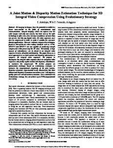
An optical configuration necessary to record one stage orthoscopic 3D integral images has been proposed [6-8] and is shown in figure 1. This employs a pair of microlens arrays placed back to back and separated by their joint focal length, which produces spatial inversion. The arrangement allows a pseudoscopic image to be transferred such that it can straddle a separate microlens recording array (close imaging). The recording micro-lens array can be put anywhere in the transferred image space to allow the desired effect to be achieved freely: The object can be entirely inside of the display, outside of the display, or even straddling the display. The space transfer imaging scheme offers the flexibility of recording the object at a desired depth. The system uses an additional lens array, which images the object space around the plane of the microlens combination. This arrangement has been termed a two-tier optical combination. Effectively the first macro array produces a number of pseudoscopic, laterally inverted, images around the double integral microlens screen. This image is transmitted effectively negating the sign of the input angle such that each point in object space is returned to the same position in image space. The arrangement performs pseudo phase conjugation, i.e. transfer of volumetric data in space. The image is transmitted with equal lateral longitudinal magnification, and the relative spatial co-ordinates, are preserved i.e. there is no inversion in the recorded image and no scale reduction in depth. It is possible to capture integral 3D images electronically using a commercially available CCD array [6-8]. This form of capture requires a high resolution CCD together with specialised optical components to record the micro-images fields produced by precision micro-optics. The two-tier system shown in figure 1 has been used for the capture of the integral images used in this work. The object/scene is recorded on a film placed behind the recording microlens array through a rectangular aperture. The recorded data is then scanned using a high resolution scanner. The aperture greatly affects the characteristics of the microimages recorded. Since each micro-image is an image of the object seen through the aperture independently, its shape and size is determined by the aperture. If the field of a microimage is fully covered by the image, it is said to be fully-filled, otherwise it is said to be under-filled or over-filled. Underfilled micro-images are caused by smaller aperture size than the correct size, and lead to decreased effective viewing zone with large part of the image area invalid when the image is replayed. Over-filled micro-images on the other hand are caused by bigger aperture size than the correct one. The overlapped micro-images lead to confusion in image reconstruction, thus degrade the replay quality. The system is setup to avoid over-filled micro-images to obtain a good 3D integral image quality. The system would record live images in a regular block pixel pattern. The planar intensity distribution representing an integral image is comprised of 2D array of M´M micro images due to the structure of the microlens array used in the capture and replay. The resulting 3D images are termed
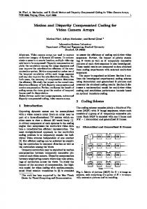
Omnidirection Integral Images (OII) and have parallax in all directions. The rectangular aperture at the front of the camera and the regular structure of the hexagonal microlenses array used in the hexagonal grid (recording microlens array) gives rise to a regular ‘brick structure’ in the intensity distribution. In this paper, the simulation work is carried out on unidirectional integral images (UII) which are obtained by using a special case of the integral 3D imaging system where 1D cylindrical microlens array is used for capture and replay instead of a 2D array of microlenses. The resulting images contain parallax in the horizontal direction only. Figure 2(a) shows an electronically captured unidirectional integral 3D image and figure 2(b) shows a magnified section of the image. The M vertically running bands present in the planar intensity distribution captured by the integral 3D camera are due to the regular structure of the 1D cylindrical microlens array used in the capture process.
(a)
(b) Figure 2 An electronically captured unidirectional integral image a) Full. b) Magnification
Authorized licensed use limited to: Brunel University. Downloaded on October 8, 2008 at 12:55 from IEEE Xplore. Restrictions apply.
S. Adedoyin et al.: A Joint Motion & Disparity Motion Estimation Technique for 3D Integral Video Compression Using Evolutionary Strategy
III.
Proposed 3D Video Encoder With ES-Based ME
Evolutionary computation (EC) theories were developed originally from observing natural evolution of life form. Because of this, the terminology surrounding the field of EC is full of analogies with natural evolutionary process. It was particularly from Darwin’s theories [26] that the best techniques regarding the optimization, modelling and the control of unknown processes were developed. EC has long been exploited in the video coding field. A very well known form of EC called Genetic Algorithm (GA) was used to perform image registration as part of a larger Digital Subtraction Angiography (DAS) system [27][28]. Subsequently, GA search algorithm has been applied for motion estimation [29][30][31][32]. Hardware implementation of Four-Step genetic search algorithm was proposed in [29]. Similarly, the Evolutionary Strategies (ES) were developed to solve technical optimization problems in video coding field. Thus, the motion and disparity estimation has been carried out using a (1+λ) rudimentary ES for stereoscopic video sequences, which includes calculation of P- and B-frames, weighted prediction, joint motion disparity estimation [33][34]. In this paper, we apply ES to estimate the motion and inter-view disparity vectors in lenticular video coding. A. Coding structure Each viewpoint video sequence represents a unique recording direction of the object scene. Hence the 3D integral video sequence can be separated into its respective distinctive viewpoint videos. Figure 3 illustrates the viewpoint extraction for a lenticular video of 4 distinctive viewpoints. Columns of pixels formed by each micro lens representing the similar view points are placed near to each other to form the viewpoint images. These viewpoint video sequences are used in the motion compensation.
The best motion vectors for each viewpoint can be found by applying a conventional block-matching algorithm. However such a technique would be too complex and time consuming. Since viewpoint images are captured by slightly different viewing angles, there is a great deal of redundancies. Therefore, it is advantageous to find a proper set of motion vectors only for a single viewpoint and utilize this correlation to minimize the overall coding complexity. Compression efficiency can be maximized if disparity correlations amongst the viewpoints are also considered. Exploitation of such additional redundancies, however, increases the computational complexity further. Therefore, there is a great deal of necessity for an efficient technique to exploit most of the existing correlations within lenticular video at an acceptable computational cost. Following this argument, we propose to motion compensate one of the middlemost viewpoints and the rest of the view points are motion and disparity compensate jointly considering the motion compensated viewpoint as the base viewpoint. Proposed structure is illustrated in Figure 4. Please note that the figure represents only the first five view points. After coding the base viewpoint (i.e. Viewpoint 5) with respect to the base viewpoint of the reference frame, viewpoint 3 is coded taking the corresponding viewpoint from the reference frame and the reconstructed version of the base
Reference Frame
Current Frame
….
….
Viewpoint 1
Viewpoint 2
Viewpoint 3
Viewpoint 4
Viewpoint 5 Base viewpoint
Motion Prediction Disparity Prediction
Figure 3 Viewpoint extraction
735
Figure 4 Proposed motion and disparity estimation technique
Authorized licensed use limited to: Brunel University. Downloaded on October 8, 2008 at 12:55 from IEEE Xplore. Restrictions apply.
IEEE Transactions on Consumer Electronics, Vol. 53, No. 2, MAY 2007
736
viewpoint of the current frame as references. Subsequently, the viewpoint 4 is coded taking reconstructed versions of the viewpoint 3 and 5 of the current frame and the viewpoint 4 of the reference frame as references. This process is repeated for the other viewpoints in the sequence. Use of an exhaustive search technique such as full search would result in an unacceptable computational complexity. We propose to use evolutionary strategy to minimize the computational complexity. B. Proposed evolutionary strategy ES typically uses deterministic selection in which the worst solutions are purged from the population based directly on their fitness function value. The (μ+λ)-Evolutionary Strategy demonstrated in Figure 5 is used in this work with an increasing level of imitation of biological evolution [35], where μ means the total number of parents in previous population, and λ stands for the number of offspring generated from mutated parents.
x Object gene
y Strategy gene
Object gene
reference Strategy gene
Object gene
Strategy gene
(a) x
-1
y
10
1
reference
-12
1
0
(b) Figure 6 Chromosome representation (a) General representation of chromosome; (b) an example of chromosome
D. Fitness Function The quality of the chromosome is defined by fitness function. Fitness function is calculated based on the Sum of Absolute Difference (SAD). Each chromosome in newly generated population is evaluated using fitness function. E. Evolutionary strategy operators
Figure 5 (μ+λ)-Evolutionary Strategy-based motion estimation algorithm
C. Chromosome representation Each chromosome represents three elements of a motion vector, i.e. the data for coordinates x and y and the reference frame (in case of a motion compensation) or viewpoint (in case of a disparity compensation). Each element is described by 2 genes: object and strategy genes as shown in the Figure 6 (a). Object gene defines the actual value of the element. x and y represent the horizontal component of the motion/disparity vector. reference represents whether the vector is a motion vector or a disparity vector and if it is a disparity vector, whether it is upper viewpoint or the lower viewpoint. Values of the object genes determine how large the mutation is. The value of object gene of x and y are determined from the search window size. For example, if the search window is within the range [-16, 16], then the value of object gene can take any integer number inside of this range. The search window size depends on the maximum motion vector size. Strategy gene determines whatever local or global search will be carried out. Smaller value of strategy gene more localised become the search process. The negative value defines the decrement of mutated gene and positive values respectively determine the increment of the mutated gene. The strategy parameter depends on the window size and can take any value up to its maximum. In order to implement the local search, we choose to set the strategy parameter to values -1 or 1.
In order to reduce the number of generations required to obtain the satisfactory solution, the initial population is generated from randomly generated chromosomes. However since the argument of a large number of motion vectors is equal or closer to zero, (0, 0) motion and disparity vectors are also included in the initial generation. Selection takes place only amongst the offspring’s (mutated values) and parents. The size of population in the next generation is fixed and set to 20 individuals. The new population is generated from the 20 best chromosomes from the previous population that combines both parents and offspring as shown in Figure 1. Mutation rate defines the percentage of genes to be mutated in a newly generated population. Mutation rate used in the experiments was set to 8.5%. In general the value of the strategy gene is generated randomly from the local search increment window specified in advance. In our case, the strategy gene value can vary within the range [-1, 1]. For example, if the strategy gene in the x coordinate shown in Figure 6 (b) is chosen to be mutated, then its value will be changed to 1. The new value of the object gene (if this gene has been chosen to be mutated) is defined as following: new xop = xop + x sp
[1]
new where xop is the new value of mutated object gene for x
coordinate, xop and xsp are the values of object and strategy genes for x coordinate respectively. Similarly the genes for y coordinate and the reference are calculated. Let us consider an example shown in Figure 6 (b). The value of x coordinate is 10, if this gene has been chosen to participate in mutation, the value of this gene will be
Authorized licensed use limited to: Brunel University. Downloaded on October 8, 2008 at 12:55 from IEEE Xplore. Restrictions apply.
S. Adedoyin et al.: A Joint Motion & Disparity Motion Estimation Technique for 3D Integral Video Compression Using Evolutionary Strategy
Table 1 Number of search points Full search ES search Motion
1024 3072
37 35
RESULTS
Proposed joint motion and disparity estimation technique is implemented in a 3D-DCT integral image codec based on the architecture described in [12] for performance evaluation. An adaptive arithmetic coder is used for the entropy coding and the quantizer step size ranged from 10 – 50. The population size of 30 was used for ES. The number of generation and the mutation rate are set to 10 and 0.17 respectively based on preliminary experimental results. Peak Signal-to-Noise Ratio (PSNR) is used to measure the objective quality. Figure 7-10 show the objective quality comparison of the proposed ES based joint motion and disparity estimation technique (denoted as ES-JM&D) for the Room integral video test sequence of image size 512×512 against three reference cases namely: (i) Motion only full search (FS-MOTION) – motion compensated prediction is used and the motion vectors are calculated using the full search algorithm. (ii) Motion only ES search (ES-MOTION) – as above except full search is replaced with ES search. (iii) Joint motion and disparity full search (FS-JM&D) – joint motion and disparity compensated prediction is used with ES search. Figure 7, Figure 8 and Figure 9 depict the relative performance of the above algorithms for selected viewpoints and Figure 10 does for the entire frame. Results show that FSJM&D has outperformed FS-MOTION by over 1 dB. This is a clear evidence that the use of disparity redundancies together with the motion can greatly improve the compression efficiency. However, as described in the section 3, this improvement comes at an expense of multifold increment in the computational complexity. This is where ES become helpful. According to Table 1, ES gives an 84% decrease in coding complexity over Motion Search and over 90% decrease in coding complexity over disparity. It is clear that the ES significantly minimizes the computational complexity. According to Figure 7-10, however, there is a slight objective quality penalty. Still the proposed technique has achieved over 1 dB objective quality gain.
Disparity
39
132 183
Complexity gain
87.11% 94.04%
33 31 FS-MOTION
29
FS-JM&D ES-MOTION
27
ES-JM&D
25 0.5
1
1.5
2
2.5
3
Bitrate (bpp)
Figure 7 Objective quality comparison for the viewpoint 2 Viewpoint 4 41 39 37 35 P S NR (dB)
IV.
Viewpoint 2 41
P S NR (dB)
decremented by 1 and a new gene will be produced with an object gene equaled to 9. In the case of the y coordinate with an object parameter of value -12, this will be incremented by one, if it is chosen to be mutated and therefore will produce a new gene with an object gene value of -11. The new reference would be 1, if it is elected to be mutated. Mutation rate defines the percentage of genes to be mutated in the population. In the current work, 8.5% of the genes randomly selected from the population are mutated.
737
33 31 FS-MOTION
29
FS-JM&D ES-MOTION
27
ES-JM&D
25 0.5
1
1.5
2
2.5
3
Bitrate (bpp)
Figure 8 Objective quality comparison for the viewpoint 4
V.
CONCLUSION
This paper proposes a novel technique to exploit motion and disparity redundancies in 3D integral video sequence and low complexity optimization technique. The integral video sequence is decomposed down to viewpoint video sequences and the motion and disparity redundancies are jointly exploited to maximize the compression efficiency. We further proposed an optimization technique based on evolutionary strategies to minimize the computational complexity of the joint motion-disparity estimation. Experimental results show that ES based joint motion and disparity estimation technique achieve over 1 dB objective quality gain while maintaining up to 94% computational cost saving.
Authorized licensed use limited to: Brunel University. Downloaded on October 8, 2008 at 12:55 from IEEE Xplore. Restrictions apply.
IEEE Transactions on Consumer Electronics, Vol. 53, No. 2, MAY 2007
738 Viewpoint 8 41 39 37
PSNR (dB)
35 33 31 FS-MOTION
29
FS-JM&D ES-MOTION
27
ES-JM&D
25 0.5
1
1.5
2
2.5
3
Bitrate (bpp)
Figure 9 Objective quality comparison for the viewpoint 8 Integral 41 39 37
PSNR (dB)
35 33 31
FS-MOTION FS-JM&D
29
ES-MOTION ES-JM&D
27 25 0.5
1
1.5
2
2.5
3
Bitrate (bpp)
Figure 10 Objective quality comparison for the complete integral video
VI.
REFERENCES
[1] T. Motoki, H. Isono, and I. Yuyama, ‘Present status of threedimensional television research’, Proc. IEEE, vol. 83, pp. 10091021 (1995). [2] T. Okoshi, ‘Three-Dimensional Imaging Techniques’, Academic Press, Inc., London, UK. (1976). [3] S. A. Benton ed., ‘Selected papers on three dimensional displays’ SPIE Optical Engineering Press, Bellingham, Wash. (2001). [4] S. V. Vladimir, J.-Y. Son, B. Javidi, S.-K. Kim, D.-S. Kim, “Moire minimization condition in three-dimensional image displays,” Journal of display technology, Vol. 1, No. 2, pp. 347353 (2005). [5] N.A. Dodgson, ‘Autostereoscopic 3D Displays’ IEEE Computer vol. 38(8), pp. 31 – 36 (2005). [6] N. Davies et al., ‘Three-dimensional imaging systems: A new development’, Appl. Optics, vol. 27, pp. 4520-4528 (1988). [7] Monaleche S., Aggoun A., McCormick A., Davies N. and Kung S. Y., ‘Analytical model of a 3d recording camera system using circular and hexagonal based spherical microlenses’, J. Opt. Soc. Am. A, Vol. 18(8), pp. 1814-1821 (2001).
[8] Davis N., McCormick M., and Brewin M., ‘Design and analysis of an image transfer system using microlens arrays’, Optical Engineering, vol. 33(11), pp. 3624-3633 (1994). [9] Martinez-Cuenca, R., Saavedra, G., Martinez-Corral, M., Javidi, B., ‘Extended depth-of-field 3-D display and visualization by combination of amplitude-modulated microlenses and deconvolution tools’ IEEE/OSA Journal of display technology, Vol. 1 (2), pp. 321– 327, (2005). [10] Okano F., Hoshino H., Arai J. and Yuyama I., ‘Real-time pickup method for a three-dimensional image based on integral photography’, Apply Optical, Vol. 36, pp.1598-1604 (1997). [11] M. Martínez-Corral, B. Javidi, R. Martínez-Cuenca and G. Saavedra, ‘Formation of real, orthoscopic integral images by smart pixel mapping’, Optics Express 13, pp. 9175-9180 (2005) [12] A Aggoun: ‘A 3D DCT Compression Algorithm For Omnidirectional Integral Images’ ICASSP 2006. [13] Zaharia R., Aggoun A. and McCormick M., ‘Adaptive 3D-DCT compression algorithm for continuous parallax 3D integral imaging’ Journal of Signal Processing: Image Communications, Vol. 17(3), pp. 231-242 (2002). [14] R Zaharia, A Aggoun and M McCormick: ‘Compression of full parallax colour Integral 3D TV Image Data based on subsampling of chrominance components‘ Proceedings of Data Compression Conference, DCC 2001, 27-29 March 2001, Snowbird, Utah, USA. IEEE Computer Society, 2001, ISBN 07695-1031-0, pp. 527. [15] Forman, M.C. and Aggoun, A., ‘Quantisation strategies for 3D_DCT based compression of full parallax 3D images’, IPA97, Conf. Pub. No.443, IEE, (1997). [16] Lippmann, G. ‘Eppreuves Reversibles Donnat Durelief’, J. Phys. Paris 821 (1908). [17] [18] W.U. ChungHong, “Depth Measurement In Integral Images” PhD Thesis, pp. 40-60, 2003. [19] Meriem Mazri and Amar Aggoun “Compression of 3D Integral Images using Wavelet decomposition” Proc. SPIE Vol. 5150, pp. 1181-1192,2003. [20] N. Davies, M. McCormick, and L. Yang, “Three dimensional imaging systems: A new development”, Appl. Opt., Vol. 27, pp. 4520-4528, 1988. [21] N. Davies, M. McCormick, and M. Brewin, “The design and analysis of an image transfer system using microlens arrays”, Optical Engineering, Vol. 33, pp. 3624-3633, November , 1994. [22] M. C. Forman, “Compression of Integral Three-Dimensional Television Pictures”, PhD Thesis, January, 2000. [23] G. Lippmann, “Epreuves reversibles”, Photog. Integr. Comp. Rend., Vol. 146, pp. 446-451, 1908. [24] H. E. Ives, “Optical properties of a Lippmann lenticulated sheet”, J. Opt. Soc. Amer., Vol. 21, pp. 171-176, 1931. [25] R. Zaharia, A. Aggoun and M. McCormick “Adaptive 3D-DCT compression algorithm for continuous parallax 3D integral imaging,” Signal Processing: Image Communication, 17, pp. 231-242, 2002. [26] Charles Darwin, “The Origin of Species: By Means of Natural Selection or the Preservation of Favoured Races in the Struggle for Life (Bantam Classic),” Bantam Classics, Reprint. 1999. [27] Fitzpatrick, J.M., Grefenstette, J.J. and Van-Gucht, D. “Image registration by genetic search,” Proceedings of Southeastcon 84, Louisville, KY, 460-464, Apr 1984. [28] Grefenstette, J.J. and Fitzpatrick, J.M. “Genetic search with approximate function evaluations,” Proc. Intl. Conf. on Genetic Algorithms and their Applications, Pittsburgh, PA, 112-120, Jul. 1985. [29] Man F. So & Angus Wu, “Hardware Implementation of FourStep Genetic Search Algorithm”, IEEE Signal Processing
Authorized licensed use limited to: Brunel University. Downloaded on October 8, 2008 at 12:55 from IEEE Xplore. Restrictions apply.
S. Adedoyin et al.: A Joint Motion & Disparity Motion Estimation Technique for 3D Integral Video Compression Using Evolutionary Strategy
[30]
[31]
[32]
[33]
[34]
[35]
Society 1999 Workshop on Multimedia Signal Processing, Copenhagen, Denmark, September 1999. Xu Yuelei, Bi Duyan and Mao Baixin, “ A Genetic Search Algorithm For Motion Estimation”, Proceedings of 5th International Conference on Signal Processing Proceedings, Beijing, China, 2000. Guanghua Qiu, Chaohuan Hou, “A New Fast Algorithm for the Estimation of Block Motion Vectors”, Proceedings of 3rd International Conference on Signal Processing, Beijing, China, 1996. Shen Li, Wei-pu Xu, Hui Wang, Nan-ning Zheng, “A Novel Fast Motion Estimation Method Based on Genetic Algorithm”, Proceedings of International Conference on Signal Processing, Kobe, Japan, 1999. K. Ponudurai, W.A.C. Fernando and K.K. Loo, “Joint Motion and Disparity Estimation in Stereo Video Sequences Using Evolutionary Strategy,” Proceedings of 1st Regional Conference on ICT and E-Paradigms, Colombo, Sri Lanka, 2004. K. Ponudurai, W.A.C. Fernando and K.K. Loo, “Joint Motion and Disparity Estimation in Stereo Video Sequences Using Evolutionary Strategy,” Proceedings of The Seventh International Symposium on Wireless Personal Multimedia Communications, Abano Terme, Italy, September 2004. Ingo Rechenberg, Evolutionsstrategie '94. Stuttgart: FrommannHolzboog 1994. Steven Adedoyin is a research student at Brunel University. He holds a BEng (Hons) in Microelectronics Engineering that was obtained from Brunel University. His current research interest lies in 3D integral imaging, 3D video coding and H.264.
739
W.A.C. Fernando received the B.Sc. Engineering degree (First class) in Electronic and Telecommunications Engineering from the University of Moratuwa, Sri Lanka in 1995 and the MEng degree (Distinction) in Telecommunications from Asian Institute of Technology (AIT), Bangkok, Thailand in 1997. He has completed his PhD at the Department of Electrical and Electronic Engineering, University of Bristol, UK in February 2001. Currently, he is a lecture in signal processing at the Brunel University, UK. Prior to that, he was an assistant professor in AIT. His current research interests include digital image and video processing, intelligent video encoding, OFDM and CDMA for wireless channels, channel coding and modulation schemes for wireless channels. He has published more than 115 international papers on these areas. Amar Aggoun (M’ 99) received the “Ingenieur d’Etat” degree in electronic engineering from Ecole Nationale Polytechnique of Algiers (ENPA) Algeria, in 1986 and the PhD degree in compressed video signal processing from Nottingham University, UK, in 1991. From 1991-1993 he was with the Nottingham University as a research fellow in digital video signal processing. From 1993-2005, he was with De Montfort University, UK, as a Principle lecturer in Electronic Engineering. In 2005, he joined the school of Design and Engineering at Brunel University (UK) as a Reader in 3D Imaging Technologies. His current research Interests include computer generation and live capture of 3D integral images, depth measurement and volumetric data reconstruction from 3D integral images, 3D video coding, computer vision, and real-time digital image processing architectures.
Authorized licensed use limited to: Brunel University. Downloaded on October 8, 2008 at 12:55 from IEEE Xplore. Restrictions apply.