Journal of Creative Sustainable Architecture & Built Environment, CSABE Vol. 1, Novermber, 2011
Environment Control Systems for Sustainable Design: A Methodology for Testing, Simulating and Comparing Kinetic Facade Systems Karen Kensek* and Ryan Hansanuwat School of Architecture, University of Southern California, US *E-mail:
[email protected] Abstract The primary purpose of the building envelope is to protect the inhabitants from the outside environment. Although usually static systems, facades are designed to respond to many scenarios and perform functions that can be contradictory to each other: daylighting versus energy efficiency, ventilation versus views and energy generation. By actuating the facades and making them dynamic, they can better adapt to the conditions, provide for improved comfort of the occupants, and achieve a more sustainable design by reducing the compromises needed for that balance. Facades can now sense the environment and make their own modifications in order to achieve prescribed goals. Kinetic solutions can be analyzed for their environmental benefits, compared to each other, and recommendations proposed. This project demonstrates the development of a kinetic façade system based on research, simulations, and a built prototype that improves upon current practice and provides an efficient façade for traditional curtain-walled office buildings. Keywords: Kinetic façade, Building envelope, Shading device, Performance-based design
1. Introduction There has been a trend in office building design to use more glass in the façade; this often necessitates methods of mitigating undesired consequences. These glass facades are desirable to designers because they offer the inhabitants views to the outside, access to natural light, and can be visually appealing. Many solutions to mitigating the negative aspects offer solutions to single problems and are not variable enough to control more than one issue at a time. Compared to a building with a static shading, daylighting, ventilating or energy generating systems or none of these at all, the use of a kinetic façade system will diminish the need for external energy expenditures by decreasing unwanted solar heat gain or loss, increasing use of natural lighting, and generating on-site energy, while also increasing the use of natural ventilation. Through the variability of the system, the façade will adapt itself to the best situation for the given environmental condition and thus increase its potential impact. Kinetic façade systems can help to mitigate environmental problems, decrease the need for mechanical systems such as HVAC systems and artificial lighting, add to the occupants’ comfort, and potentially could be used to generate electricity. These kinetic systems are not intended to replace mechanical systems, but they could decrease the energy demands of the building significantly. It will be shown that a kinetic system can improve solar thermal load, daylighting, ventilation, and energy generation for typical all-glass facades in office buildings, is buildable, and can perform in a simple, efficient manner. Although a working prototype was built and tested, this paper will focus more on the research methodology.
27
Journal of Creative Sustainable Architecture & Built Environment Vol. 1, November, 2011
2. Environmental Mediators The introduction of dynamic facades introduces a new way to control the environment. Hoberman states, “[…] adaptive systems combine the best of existing strategies: low energy use and control over building environments. For instance, a building’s energy requirements can be considerably lowered if its design can adapt to diurnal fluctuations in temperature. An adaptive system that is modulated to control the volume and direction of heat flow in response to external and internal conditions can enhance comfort and energy performance” [1]. Historically, the use of dynamic kinetic facades as an environmental mediator has been in the control of four major variables: solar thermal control, daylighting control, ventilation control, and energy generation. Solar thermal can be controlled by various devices in a kinetic façade, ranging from automated louvers to adjustable overhangs. The intent of these systems is to either allow or deny solar radiation into the space by adjusting a device on either the interior or exterior of the building. Givoni claims, “Operable shading devices can admit all of the solar radiation when this is desirable, as it is in winter. Therefore, they are inherently more effective than the fixed shading. Operable external shading devices can reduce solar heat gain through windows and other glazed areas down to about 10 to 15% of the radiation impinging on the wall” [2]. Daylighting control is another aspect in which kinetic facades could be a major benefit. Systems similar to those used for solar thermal control, such as blinds and shade systems, can also be used for daylighting. These systems have the advantage of not having a reduced effect when placed on the interior. Louver systems are also very adept at controlling the amount of daylighting, which can range from zero to complete light intrusion depending on the angle of the louvers. Overhang systems are also highly effective systems for daylighting control, but do have limitations depending on the site conditions and hourly, daily, and annual conditions. There are also much more complex and technical systems that are intended to control daylight, such as iris systems and electrochromic windows. Other more exotic systems exist that could also be used; for example, solar control through the use of layers of mechanical “fritting” devices [3] or the use of cellular automata that could control the average shading opacity of a window [4]. Ventilation control by kinetic facades offers great potential in the area of naturally ventilated buildings. Many buildings that use kinetic systems for ventilation control do so with variable louver systems or double-skinned envelopes utilizing the stack effect. The use of these two systems is then categorized by a direct or indirect ventilation effect. In the direct ventilation scenario, the louvers or opening devices allow for the direct airflow into the space and to directly affect the user. It is often necessary to open opposing sides of the envelope to induce a cross draft, and this is often not possible in highly partitioned or large buildings. Givoni showed that the subdivision of the internal spaces has a definite and adverse effect on the flows of air through a building [5]. The difficulty in using this kind of system is that it relies heavily upon wind velocity and direction, and wind is a highly variable effect and is not predictable. Another important aspect that kinetic façade systems can incorporate is that of energy generation. Recently, systems such as building integrated photovoltaic systems (BIPV) have grown in use, and the technology is increasing to a very plausible level. Building envelopes have typically been classified as a filter, connector, barrier, and switch [6], but recently there has been another function added to the list, that of an energy creation system [7]. Kinetic systems can increase the efficiency of these building integrated systems by allowing for adjustment to the photovoltaic panels in order to track the solar movement.
28
Journal of Creative Sustainable Architecture & Built Environment, CSABE Vol. 1, Novermber, 2011
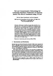
3. Computer Simulations In order to study the effectiveness of the kinetic systems, numerous computer simulations were analyzed and compared to quantize benefits for four different building elements (overhang, folding, horizontal louver, and vertical louver), for each various environmental aspect: solar thermal, daylighting, ventilation, and energy generation. 3.1 Test Case Selection Criteria A typical office layout was selected, consisting of a 15'-0” x 20'-0” interior space with windows on one side [8]. A desk was placed 5’ in from the window and set at a standard work height of 2'-6”. Windows were placed at 3'-0” sill height, were 5'-0” high, and ran the entire width of the facade. For ventilation studies, it was assumed that the lower half of the windows were operable. Glass panes were double-pane construction with a 1/8” air gap between panes and a 60% visible light transmisivity for the glass. Of the many potential choices for a kinetic facade, four external systems were selected for this study, as they are the most common and simplest: overhang, folding, horizontal louver, and vertical louver. The overhang system is a horizontal external plane, hinged at the window head, allowing it to rotate from vertical (0 degrees) to horizontal (90 degrees). The folding system is a series of two external planes that are hinged in the middle, allowing the bottom rail to slide along the vertical axis of the window, causing the two planes to fold. The louver systems are a series of either horizontal or vertical planes that create an array over the window surface. 3.2 Test Case Location Selection The building location was chosen based on providing a range in the weather data and a location with a density of office buildings. Climate Consultant 4 and Weather Tool were used to narrow down the choices. The test case location chosen was Dallas, Texas. This area features fairly equal heating and cooling periods, temperatures ranging from 35 F to over 95 F, and as shown on the psychrometric chart, 23.6% of the hours can be kept within the comfort range by sun shading and 13.4% through natural ventilation. 3.3 Solar Thermal Simulations The Department of Energy's eQuest software was used iteratively to test for solar thermal benefits. Five different models were built to represent the various kinetic facade systems being tested and the control test. The simulations were run with the same settings for each system: a two-story office building with 50% by area windows on both floors, default DX coils for cooling, default furnace for heating. Only the external shading components changed.
29
Journal of Creative Sustainable Architecture & Built Environment Vol. 1, November, 2011
Figure 1: Climate Consultant 4 Temperature Data and Psychrometric Chart for Dallas, Texas
Figure 2: Kinetic façade systems, overhang, folding, horizontal louver, and vertical louver The purpose of the first run of the control test (no external shading system) was to be able to later compare the different shading systems to a traditional office construction; this set the baseline case. The second test run was for a 5’ overhang, with simulations for four angular settings of 0 (vertical), 30, 60, and 90 degrees (horizontal). The third test run was for the folding system, a 2’-6” device hinged in the middle, meant to mimic a system that slides along tracks and folds upon itself, for each of the same angular settings as the overhang. The fourth test was on the 6” horizontal louver system, similar to external blinds, for each angle. The last test was on the 2’ vertical louver system, for each angular setting. This system is similar to the horizontal louver system as they are at a fixed distance from the glazing with an individual rotation, but these louvers are oriented vertically to the building and can thus directly track the sun in its daily path.
Figure 3: eQuest model of overhang system showing 5’-0” overhangs on all four directions at 90 degrees (horizontal)(left) and model of vertical louver system at 90 degrees (azimuth)(right)
30
Journal of Creative Sustainable Architecture & Built Environment, CSABE Vol. 1, Novermber, 2011
After the simulations were run for the control and each kinetic type, a report was generated to show the electricity consumption (cooling) and gas consumption (heating) of the building on an hourly basis. This data was input into a spreadsheet that showed the cooling electric consumption in kWh and heating gas consumption in kBtu. The five systems were then compared to each other to find which system performed better for each hour. A combined system for each kinetic type was created by finding the best performance angle for the given hour, showing the results of a kinetic system through an iterative process. This combined kinetic system was then compared to the control system without shading and the best performer of the fixed angle systems.
Figure 4: Sample eQuest annual report for the electricity and gas consumption of the building 3.4 Daylighting Simulations Simulations for daylighting performance were studied for the same four systems plus a control, for four different angular settings each, using Autodesk's 3ds Max Design software. A model was built following the same criteria as the solar thermal test, with a light meter placed on the work surface at 2’-6” and standing height 6’-0”. The sky condition for these runs was a CIE Clear Sky; this is important for Dallas, Texas, as using the overcast sky
31
Journal of Creative Sustainable Architecture & Built Environment Vol. 1, November, 2011
method would give inaccurate results. Iterative runs were performed for each system at each angular setting with the 0 degree setting omitted; it will always show zero daylighting. Each run was performed for four times of the year (March 21, June 21, September 21, and December 2) and at three times of the day (9:00 am, noon and 3:00 pm) in order to take into account the sun’s highest and lowest points and the furthest north and south settings. The data output from the program was for 18 points on each light meter, giving the total amount of luminance and illuminance on the surface in lux.
Figure 5: Autodesk 3dsMax Design model for daylighting analysis with light meters placed at work plane height (30”) and standing height (72”) and model with weather data information and date/time settings Table 1: Sample spreadsheet of lux levels for light meter Louver - 30 degrees ID 1 2 3 4 5 6 7 8 9 10 11 12 13 14 15 16 17 18
Date 12:00:00 Monday 12:00:00 Monday 12:00:00 Monday 12:00:00 Monday 12:00:00 Monday 12:00:00 Monday 12:00:00 Monday 12:00:00 Monday 12:00:00 Monday 12:00:00 Monday 12:00:00 Monday 12:00:00 Monday 12:00:00 Monday 12:00:00 Monday 12:00:00 Monday 12:00:00 Monday 12:00:00 Monday 12:00:00 Monday
March 21 1994 March 21 1994 March 21 1994 March 21 1994 March 21 1994 March 21 1994 March 21 1994 March 21 1994 March 21 1994 March 21 1994 March 21 1994 March 21 1994 March 21 1994 March 21 1994 March 21 1994 March 21 1994 March 21 1994 March 21 1994 Points in Range:
Total 53.7 254 10.7 7.3 0 0 80.8 0 0 0 0 69.9 0 0 96.9 125 0 0
Min 200 200 200 200 200 200 200 200 200 200 200 200 200 200 200 200 200 200
Max 500 500 500 500 500 500 500 500 500 500 500 500 500 500 500 500 500 500
1
Once input into the spreadsheet, the daylight levels were compared to recommended light levels for a category D office setting of 200-500 lux [9]. Each point was calculated for their
32
Journal of Creative Sustainable Architecture & Built Environment, CSABE Vol. 1, Novermber, 2011
degree of variance from the recommended values and totaled for each setting. The number of points were counted that were in the recommended range for that given date and time setting and then totaled to find the number of points on the light meter surface that fall within the recommended range. This was then shown as a percentage of the total area that falls within the recommended range for the three selected times of day for the four months of the year. A combined system was again taken as the angle setting that produced the largest amount of points within the recommended range for the given time and combined to simulate the kinetic movement. This combined system was then compared to the control and best fixed system again. 3.5 Ventilation Simulations The intent of studying kinetic facades for ventilation is to measure their ability to introduce natural air movement into a space. Computational fluid dynamic simulations were created to qualitatively compare the various systems by studying the airflow rate in meters per second. Air flow rate was chosen over volumetric air flow in cubic feet per minute because the cooling effect of motion past the body is only accountable through a velocity measure and cannot be accounted for by a traditional volumetric airflow rate. According to Olgyay, wind flow can possibly lower the temperature comfort sensation from 2-7 degrees Fahrenheit if the wind speeds range from 0.25 m/s to above 1.52 m/s. Wind speeds ranging from 0.25 to 0.51 m/s can result in a drop in 2-3 degrees Fahrenheit and produce a pleasant sensation. A generally pleasant wind speed at 0.51 to 1.02 m/s can produce a 4-5 degree Fahrenheit drop, but also causes constant awareness of air movement. Wind speeds upwards of 1.02 to 1.52 m/s cause a 5-7 degree Fahrenheit drop, but is generally considered “drafty.” Any wind speeds above 1.52 m/s can be unpleasant and are generally not comfortable [10]. These considerations were taken into account in the computer simulation, and an analysis method was determined. In order to test the wind velocity conditions for each kinetic system for the location, an Ecotect model was produced that mimicked the typical office setup with the bottom half of the window set to be operable, which for the purposes of the test was set to a void. Climate Consultant 4 was referenced to find the appropriate wind direction and velocity for the site -- 175 degrees (south) in the summer and 230 degrees (south-west) in the winter, with an average wind speed of 5 meters per second. This data was input into the control data that was exported from Ecotect to the software WinAir4. A section cut of the space was created and an image generated showing wind flows through the space. The method for converting the image to qualitative data was modified from the method developed by Pushkin Passey and uses Adobe Illustrator and Ecotect [11]. The process involves copying the side view data from Ecotect as a metafile and calculating areas with a built-in Illustrator filter. Once in Illustrator the image was un-grouped, and the analysis grid beyond the boundary deleted, with the legend being retained. The individual values were selected and Illustrator set to select any paths with a similar fill color, which would select the entire area within that given range. Once the paths selected, a path area command was initialized, giving the area in square inches of the value. This number was compared to the overall square inches for the entire built area, which would give a percentage of the area that falls within that range. Each system was compared in this manner for the varying angles and both summer and winter.
33
Journal of Creative Sustainable Architecture & Built Environment Vol. 1, November, 2011
Figure 6: CFD setting for export from Ecotect to WinAir4 (left) and Ecotect data visualization in perspective view showing section cut of analysis g rid (right)
Figure 7: Image metadata exported from Ecotect and viewed in Adobe Illustrator (left) and image of only interior space for analysis and selection/report of area(right) 3.6 Energy Generation Simulation Energy generation was calculated using software from the National Renewable Energy Laboratory called Solar Advisor Model, which uses a TRANSYS engine for calculation. Unlike the other simulations, a 3d model was not created, but was instead information was input from the known placement and data for the kinetic systems. The important pieces of data are the location, square footage of the solar panels, altitude and azimuth of the panel, and specific solar panel type. The control setting is considered to be a typical building integrated photovoltaic (BIPV) setup in place of the windows in a vertical (0 degrees) setting. The south façade was used for the test. The amount of energy generated by each setting were exported as a .csv file to a spreadsheet, where the total amount of expected energy generation in kWh was sorted, finding the settings which performed best, and combined to create a kinetic system which adjusted to produce higher levels of energy generation.
34
Journal of Creative Sustainable Architecture & Built Environment, CSABE Vol. 1, Novermber, 2011
Table 2: Sample spreadsheet of percentage of areas in wind velocity range
Figure 8: Solar Advisor Model settings with sample graph showing monthly energy generation
35
Journal of Creative Sustainable Architecture & Built Environment Vol. 1, November, 2011
Table 3: Sample spreadsheet of energy generation results
4. Results and Analysis Once the results were compiled for the various kinetic systems with each environmental variable, an analysis was performed to compare the systems amongst themselves in order to find the top performers for their respective benefits. This hierarchy is important to determine because it is possible that a setting that might be beneficial for one environmental factor may be detrimental to another. It is thus important to analyze the systems for their individual benefits and then as part of a combined system. 4.1 Solar Thermal Analysis Overall, all four systems showed consistent improvement over a non-shaded system, showing an energy reduction ranging from 28% to 30% for heating and from 28% to 33% for cooling. The reduction in energy is due to the fact that the kinetic system is able to block out more unwanted sun and allow beneficial sunlight for more hours than the fixed system. Across the board, the resulting reductions were very close between the four systems as they are able to block or allow similar amounts of direct solar gain into the building and close off the façade completely at night. During the summer hours, when it is desirable to reduce the amount of direct solar heat gain through the façade, all four facades did well. During the winter hours, when it is desirable to allow the sun to enter, the same holds true. The highest setting for the horizontal systems, perpendicular to the façade, is high enough to allow for full penetration of the sun at all hours of the day, while the vertical system can track the sun and can also allow for minute changes to compensate for the movement of the sun. Although all four systems performed remarkably well against the non-shaded system, it was the overhang and horizontal louver system that performed better, with a decrease at 33% for cooling and 30% for heating. They were able to cover more square footage in shade at certain times due to their method of rotation, whereas the folding system is only functional as a perpendicular horizontal shade for half of the window height. The improvement in performance over the vertical system is created because the kinetic system was placed on all four sides to anticipate the desire for aesthetic continuity throughout the building. When placed on the north side of the building, the vertical system is unable to allow enough light in
36
Journal of Creative Sustainable Architecture & Built Environment, CSABE Vol. 1, Novermber, 2011
as compared to the other three systems. The results, however, are so close to each other, that this effect is minimal, leading to the conclusion that it does not seem to matter which system is used as long as the façade is kinetic; any one of the systems will result in a roughly 30% increase over a non-shaded system. Table 4: Comparison of hourly needs between different fixed and kinetic shading systems versus control, on a south facing façade.
Figure 9: Standard eQuest report showing monthly and annual energy figures 4.2 Daylighting Analysis All four systems show marked improvement over a non-shaded system and a fixed angle system. Non-shaded systems consistently allowed too much sun in and produced an over-lit environment at all times throughout the year. This does not mean that the room is unbearable, but simply that the lighting level is not within the recommended range. The fixed system had the opposite problem in that it did not allow enough light to enter the room at times, and much of the time the light was not allowed to penetrate the depth of the space.
Figure 10
Figure 11
37
Journal of Creative Sustainable Architecture & Built Environment Vol. 1, November, 2011
Figure 12
Figure 13
Figure 10: Daylighting rendering of overhang system at 90 degrees, December 21st at 12:00pm Figure 11: Daylighting rendering of folding system at 90 degrees, December 21st at 12:00pm Figure 12: Daylighting rendering of horizontal louver system at 90 degrees, December 21st at 12:00pm Figure 13: Daylighting rendering of vertical louver system at 90 degrees, December 21st at 12:00pm The results show that the vertical louver system, at 55%, performed much better in allowing for the largest amount of recommended lighting into the room. While the other systems allowed for a high number of points within the recommended range, it is the vertical louver system’s ability to track the movement of the sun that was critical to its success in allowing for a more finite control of daylight entering the space. The overhang system performed almost as well with 54% of the points within range during the four times of the year; the overhang allows for a larger amount of window to be influenced by the sun, as opposed to the horizontal folding and louver systems in which the shade system itself can become a hindrance on the light entering the space. 4.3 Ventilation Analysis Simulations demonstrated that kinetic systems performed only slightly better than a standard open window and a fixed system. There is some improvement in the systems that show a similar trend to the open window, with the majority of the air flow through the space being from 0.0 to 0.2 m/s, while some systems were able to produce a higher flow at 1.0 m/s in some areas. Of the four systems tested, the vertical system again performed best; the test accounts for the wind coming in off the site based on an ordinal N-E-S-W direction, which the vertical system was able to track. The horizontal systems would only be able to be tested for wind coming from the same height, but at different ordinal directions. An air velocity of 0.25 to 1.02 m/s will produce a cooling sensation when it passes over the skin, and the kinetic systems are able to produce this, but they are not much more efficient at this than a standard operable window. It is important to note that due to the location of the operable portion of the window, all of the increased velocity ranges were maintained within the sensible range for the occupant, between three and four feet above the finish floor. The higher velocity winds were all maintained at or near 3-4 feet above the finished floor, which
38
Journal of Creative Sustainable Architecture & Built Environment, CSABE Vol. 1, Novermber, 2011
would be perceptible by the occupant. The cooling sensation from the increased wind velocity will be felt by the occupant and not simply flowing past the occupant at higher levels. The standard operable window is able to produce wind speeds from 0.3 to 0.5 m/s for 20.9% of the space in the summer and 19.5% of the space in the winter. The vertical louver system was able to produce airflows up to 1.1 m/s in some spaces, although this was not true for all times and settings. The greatest increase over this standard window is the folding system, but with only a 9% increase in summer and 15% increase in winter. In the higher velocity ranges that offer greater potential for comfort sensation temperature reduction (0.6 to 0.8 m/s), the vertical system performed the best, but offered only 12.9% increase in the summer and 6% in the winter. Overall, the kinetic systems produce a slight increase in velocity over a standard open window, but not enough to consider it a major factor.
Figure 14: Air velocity of control (open window), summer Figure 15: Air velocity of control (open window), winter Figure 16: Air velocity of vertical louver kinetic system, summer Figure 17: Air velocity of vertical louver kinetic system, winter
Figure 18: Summer airflow rates of 90 degree setting for each system
39
Journal of Creative Sustainable Architecture & Built Environment Vol. 1, November, 2011
Table 5: Sample table showing comparison of fixed versus overhang (30 degrees)
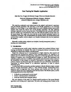
4.4 Energy generation analysis The energy generation results show that three of the four kinetic systems show improvement over a standard vertical integrated photovoltaic, with one, the folding system, showing lower energy generation numbers. As discussed previously, the folding system only contained half of the square footage. However it is interesting to note that even though it is smaller than the standard BIPV system, it was still able to produce energy levels that were only slightly lower. The overhang and horizontal louver systems have the same square footage and track in the same direction and thus produce the similar numbers. What has been found in this study is that the overhang, horizontal louver, and vertical louver kinetic systems produced higher amounts of energy than that fixed control, while the folding system actually produced less. The kinetic systems of each type produced more energy than any of their fixed settings, but with the overhang, folding, and horizontal louver, the 30 degree and 60 degree settings were very close to the kinetic system. The kinetic vertical louver system, however, resulted in a nearly 70% increase over the next closest fixed vertical louver system and a 43% increase over the next best fixed system of any type.
Figure 19: Comparison of kinetic systems versus control for energy generation for four months
40
Journal of Creative Sustainable Architecture & Built Environment, CSABE Vol. 1, Novermber, 2011
Overhang - Fixed vs Kinetic
Folding Fixed vs. Kinetic
140
140
120
120 101.62
100
91.54
95.15
100
76.83 80
80 67.13
60
59.6
56.57
54.02
60
46.12 38.85 40
40
20
20
0
0 Overhang - 0
Overhang - 30
Overhang - 60
Overhang - 90
Folding - 0
Overhang - Kinetic
Folding - 30
Horizontal Louver - Fixed vs. Kinetic
Folding - 60
Folding - 90
Folding - Kinetic
Vertical Louver - Fixed vs. Kinetic 137.87
140 140
120 120 101.62 100
91.54
100
95.15
81.31
80.95 76.83
80
75.94
73.72
80
67.13
67.13
63.11
59.65 60 60
40 40
20 20
0 0
Vertical - 90e Horizontal - 0
Horizontal - 30
Horizontal - 60
Horizontal - 90
Horizontal - Kinetic
Figure 20: Comparison of fixed overhang system Figure 21: Comparison of fixed folding system Figure 22: Comparison of fixed horizontal system Figure 23: Comparison of fixed vertical system
Vertical - 60e
Vertical - 30e
Vertical - 0
Vertical - 30w
Vertical - 60w
Vertical - 90w
Vertical Combined
system versus kinetic overhang system versus kinetic folding system versus kinetic horizontal system versus kinetic vertical
4.5 Hierarchy Based on these four results, it becomes apparent that two of the environmental factors show a large increase over the standard and fixed (solar thermal and daylighting), one factor shows improvement for some systems but not others (energy generation), while one shows only slight improvement (ventilation). It is thus decided that the a hierarchy for the advantages of kinetic systems can be described by placing solar thermal and daylighting as the most important component, energy generation being slightly less, and ventilation not much of a factor for this location.
5.0 Prototype 5.1 Assumptions for Design The second phase of this research was to take the results and use the data to inform a design that would produce the most benefit for the four environmental factors of solar thermal, daylighting, ventilation, and energy generation. A working full-scale prototype was created to test the working ability and maintenance of the design. The design itself is based upon the analysis of the virtual components and takes into account the hierarchy of needs of
41
Journal of Creative Sustainable Architecture & Built Environment Vol. 1, November, 2011
solar thermal, daylighting, energy generation and ventilation, in order of most to least important. The prototype has a larger scale overhang system that controls the solar thermal aspects of the façade. The overhang system was chosen because three of the four systems were nearly identical in their performance, but the overhang system is the simplest in terms of function and maintenance. The overhang system will be controlled based on a pre-determined manner that will allow it to shade when it is necessary and allow sun in when beneficial. Built within the overhang system is a series of vertical louvers that will allow an added level of control over the system. The vertical louvers performed the best of the four systems in terms of allowing for natural daylighting within recommended levels and are also controllable by the inhabitants. It is assumed that the control of the daylight settings will occur during normal working hours and after that the overhang settings will be the only factor. In order to achieve the highest level of energy generation without interference from the other systems, a vertical louver system will be placed in that spandrel space of the façade and act independently of the other systems. For ventilation, since it has been shown that a kinetic system offers very little improvement over a standard operable window in air velocity throughout the space, this prototype will not include this feature. This also allows for fewer concerns over durability and maintenance in the kinetic system. With energy generation considered a separate system only solar thermal and daylighting features were incorporated into the prototype.
Figure 24: Early designs of kinetic facade with smart materials (left) and with multiple hinge point folding system (right)
Figure 25: Final proposed design with overhang, vertical lo uvers and photovoltaic system(left) and rendering with 30 degree overhang and closed vertical louvers(right)
42
Journal of Creative Sustainable Architecture & Built Environment, CSABE Vol. 1, Novermber, 2011
5.2 Prototype Testing With the proposed design in mind, computer simulations were conducted using the previously described method in order to verify whether the design would provide the expected results. It was intended that the proposed design with either meet or exceed the four previous iterative settings for the best-case kinetic design. It should result in at least a 30% decrease in energy consumption for both cooling and heating needs, allow for at least 50% of the work surface to be within the recommended range for daylighting for the four times of the year, produce about 1.0 m/s of airflow, and generate about 130 kWh of energy. As mentioned previously, ventilation and energy generation were not included in the final prototype. 5.3 Building the Prototype Once the design of the kinetic system has been verified, it was important to test the design for constructability and maintenance. The intention of this prototyping was to not only see if the design would be physically possible, but to also determine methods of improving the design. Four major issues were considered: the connection of the overhang system to the aluminum structural frame, the rotation of the vertical louver system, twistable panels, and the ease or complexity of actually constructing the prototype. The construction of the prototype led to a few changes and modifications, and in the end produced a better design. The final prototype incorporates the intentions of the proposed design of an overhang system hinged one foot down to produce a simple mechanism for controlling solar properties and acting as a light shelf and a twisting vertical louver system that offered greater control in daylighting for the user.
Figure 26: Prototype Under Construction
5. Conclusions It should be noted that the analyses were only done through computer simulation. Continuation of this project should include validation of the results through testing of a built prototype. The current prototype also needs additional development. Although many practical issues were discovered during its construction, it is not ready for serious testing, and it is expected that many more problems and opportunities would be discovered during the process of truly creating a physical model for potential manufacturing purposes. See [12] for more details on the creation of this prototype. In addition, the research method presented is not the only path to achieve savings in energy while providing for day lighting and natural ventilation. It is a case study on how analysis tools were used to decide the relative importance of day lighting, ventilation, energy generation, and energy savings for the design
43
Journal of Creative Sustainable Architecture & Built Environment Vol. 1, November, 2011
of a specific kinetic façade system. One objective of this study was to show that some tradeoffs can be quantified. Choices were made in the research to balance conflicting goals, and it is apparent that in real building situations, other selections would be made in response to other aesthetic and performance based criteria. This study shows that properly designed kinetic facades can decrease energy use in a building, can produce ample amounts of recommended natural daylighting, induce preferable ventilation air velocities, and create more energy, as compared to a typical non-shaded situation. The kinetic facades studied were able to produce a roughly 30% decrease in energy consumption for both heating and cooling situations over the non-shaded system. These systems are able to shade the office space from the sun, insulate the office from heat loss when needed, and can do this at variable levels throughout the day, month, and year. Kinetic systems have been shown to keep 38-55% of the work surface in the recommended light levels, not only reducing the need for artificial lighting, but also keeping the space in a comfortable setting for the tasks required of that space, ranging from 200 to 500 lux. For daylighting purposes, it was shown that the lighting levels in the space can be vastly improved. The kinetic systems were able to produce more surfaces in the recommended range over the best fixed system by 13% for the overhang, 5% for the folding, 5% for the horizontal louver, and 18% for the vertical louver. For ventilation alone, the kinetic facades offered very little improvement over a traditional static window. In all cases the best fixed setting was to open the façade up as much as possible, thus allowing the air to flow freely into the space with as little obstruction possible. Natural ventilation has been shown to be a plausible addition to a kinetic façade, but does not have as great an increase over the control as the other environmental factors. The incorporation of photovoltaic panels in the design of these kinetic facades can also take advantage of their already mobile nature; by allowing the panels to track the sun, the efficiency of these systems is increased, with the highest increase being the vertical louver system, nearly doubling the energy output over a static BIPV. Energy generation produced dramatic increases over the best fixed systems by producing more energy by an average of 10% for four specific days of the year. This increase can be expanded upon when carried out throughout the year. The true study of these kinetic facades was not only in their ability to control any one of these aspects, but their ability to control all of these aspects at the same time. Many critics claim that the high cost of construction and maintenance for these kinetic systems cannot justify their use, and for any one of these settings it might be accurate, but if the façade is controlling all four of these aspects, the costs can be made up quickly by allowing for more efficient facades, better daylighting levels, increased natural ventilation, and the increased production of energy through the façade. The kinetic façade can control these environmental variables, all while providing a dynamic and interesting aesthetic to the building. Façades do not need to be static; computer simulation can provide some direction for the exercise of architectural creativity; and kinetic facades can be both beautiful and control the environment more effectively.
Acknowledgements We wish to thank Professors Marc Schiler and Douglas Noble for their guidance throughout the thesis process.
44
Journal of Creative Sustainable Architecture & Built Environment, CSABE Vol. 1, Novermber, 2011
References [1] Hoberman, Chuck and Schwitter, Adaptive Structures: Building for Performance and Sustainability, Design Intelligence, 2008. [2] Givoni, Baruch; Passive and Low Energy Cooling of Buildings, John Wiley, New York. p. 29, 1994. [3] Drozdowski, Ziggy and Gupta, Shawn, “Adaptive fritting as case exploration for adaptivity in architecture,” ACADIA 09: reform(): Building a Better Tomorrow [editors Sterk, Loveridge, Pancost]. pp. 105 – 109, , 2009. [4] Zawidzhi, Machi, Implementation of cellular automata for dynamic shading of building façade, acadia>08: Silicon+Skin > Biological Processes and Computation [editors Kudless, Andrew; Oxman, Neri], pp. 246 – 255, 2008. [5] Givoni, Baruch, Man climate and architecture, Elsevier, Amsterdam, copyright 1969. [6] Norberg-Schulz, Christian, Intentions in Architecture, The MIT Press, Cambridge, Massachusetts, 1965. [7] Stein, Benjamin, Reynolds, John S, Grondzik, Walter T. and Kwok, Alison G, Mechanical and Electrical Equipment for Buildings, Wiley, Hoboken, New Jersey, 2006, pp. 172-176. [8] Ramsey, Charles, Architectural Graphic Standards, John Wiley, New York. p. 876, 2000. [9] Schiler, Marc, Simplified Design of Building Lighting, John Wiley, New York. p. 82, 1992. [10] Olgyay, Victor, Design with Climate: Bioclimactic Approach to Architectural Regionalism, Princeton University Press, Princeton, 1963. [11] Passey, Pushkin, Sustainotect.com - A blog on sustainable architecture for students of sustainability, 2009. [12] Hansanuwat, Ryan, “Design and Prototype of a Kinetic Façade System to improve building efficiency and user comfort,” BESS 2010: High Performance Building Enclosures - Practical Sustainability Symposium [editors Abdelghani, Lin, Tucker], pp. 174-185, 2010.
45
Journal of Creative Sustainable Architecture & Built Environment Vol. 1, November, 2011
46