George H. Gillespie, Barrey W. Hill, Michael C. Lampel, Hendy Martono, John M. Moore,. Kyle J. Ryan .... Mottershead, R. D Ryne, E. Forest, L. M Healy, P.
A MULTI-PLATFORM GRAPHIC USER INTERFACE FOR THE PARTICLE OPTICS CODE MARYLIE George H. Gillespie, Barrey W. Hill, Michael C. Lampel, Hendy Martono, John M. Moore, Kyle J. Ryan G. H. Gillespie Associates, Inc., P.O. Box 2961, Del Mar, CA 92014, U.S.A and Alex J. Dragt Department of Physics, University of Maryland, College Park, MD 20742, U.S.A. Abstract An advanced graphic user interface (GUI) is being developed for use with the particle optics code MARYLIE. MARYLIE is based on a Lie algebra formulation of charged particle trajectory calculations and is particularly useful for particle tracking and the analysis of linear and nonlinear lattice properties. The GUI for MARYLIE uses the Multi-Platform Shell for Particle Accelerator Related Codes, a software framework developed specifically to support accelerator modeling and simulation. Transport element icons are selected from a palette and assembled into beamlines by graphical construction. Optical cells and lattices composed of element groups may be defined as sublines, and any element or subline can be replicated using an alias element. The icon-based beamlines generate entries for the #beam, #menu and #lines components of the MARYLIE Master Input File (MIF). Frequent computations, such as creating maps or generating particle distributions, are encapsulated into interactive GUI commands which create corresponding entries in the #menu, #lines and #labor components of the MIF. An icon-based description of procedural processes is being developed to support the more complex MARYLIE analysis tasks that utilize the #lumps and #loops components. Progress on the development of this GUI for MARYLIE is described and illustrations from the Windows95/NT GUI implementation are presented.
1 INTRODUCTION The Multi-Platform Shell for Particle Accelerator Related Codes (S.P.A.R.C. MP) software technology provides a framework for implementing cross platform graphical interfaces. The software architecture was designed to run on different operating systems including 32-bit Windows, UNIX/X-Windows and the Mac OS. The approach to developing the cross platform code is to implement platform specific interface libraries, each of which encapsulates an individual operating system. These interface libraries provide a common application programming interface (API) between the S.P.A.R.C. MP source code (C++) and each target operating system. The API libraries, which are a collection of basic functions utilizing OS native routines, provide a means of interacting with the different platform specific operating
systems to maintain the native “look and feel” of the graphic interfaces associated with each platform, while providing a single programming interface to all supported platforms. This approach yields a single version of the S.P.A.R.C. MP source code for all platforms. Platform specific executable applications are created by linking the compiled S.P.A.R.C. MP code with the appropriate API for that platform. S.P.A.R.C. MP was developed to interface with a variety of accelerator modeling and simulation programs. The software uses a modular approach that allows new programs to be added to the framework, without affecting the functionality of existing programs. This paper summarizes progress on the interfacing of the MARYLIE [1] code with S.P.A.R.C. MP.
2 GRAPHIC USER INTERFACE (GUI) The graphic interface for MARYLIE is patterned after that developed for the Particle Beam Optics Laboratory (PBO Lab™). The PBO Lab [2,3] has four major components: (1) a graphic user interface shell, (2) a graphic beamline construction kit, (3) a set of physics and technology tutorials, and (4) modules for various charged particle optics computation engines. Each component is described elsewhere [2,3,4,5]. A MARYLIE Module is being developed to provide significant new optics modeling and simulation capabilities. A principle requirement for the GUI is to assist users in the set up and running of MARYLIE without requiring any knowledge of the format, syntax, or similar requirements of the input. Beamlines are graphically constructed on the computer screen using drag and drop icons. Default parameters are incorporated for all required inputs so that both the topology of the beamline and a complete set of input data are defined automatically during the graphical construction. Setting up a specific problem then involves editing the values of parameters. The S.P.A.R.C. MP graphic user interface shell and the beamline construction kit [3] provide this capability for the MARYLIE GUI. Figures 1 and 2 illustrate selected windows for the GUI running under Windows 95.
848
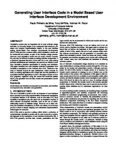
Maps may be created and used like any other Piece
Context identifies computation engine
Aliases can be used for elements or sublines
Figure 1. Example Document Window and Subline Window of the graphic user interface for MARYLIE.
Several new GUI features have been added in order to support the extensive capabilities of MARYLIE. Figure 1 illustrates the second-order achromat described in [5] in a new version of the Document Window [2,3] developed for MARYLIE. Figure 1 also illustrates two new elements of the GUI developed for MARYLIE: Alias Pieces and Map Pieces. The Map Piece is an important new element of the GUI for MARYLIE. Its full functionality is still being defined, but currently the Map Piece can be used to enter a user specified map, to create a map from a given selection of Pieces or Sublines, and to save a map for later use. The Alias Piece is one of the components of an innovative object model [6] that has been developed to describe beamlines. S.P.A.R.C. MP beamlines can be modeled using hierarchical (Sublines), flat (individual Pieces), or mixed representations that contain both Sublines and individual Pieces. This object model provides the basis for the functionality of the beamline construction kit. An alias in this object model is a Piece or Subline which is represented by a persistent link to another Piece or Subline, and is also capable of storing deviations from the original parameters without duplication of redundant data. The Alias Piece thus provides an element that can be used to efficiently replicate any other Piece, including Sublines: the only persistent data is a
pointer to the original Piece or Subline. However, Alias Pieces can also contain deviations (e.g. to represent errors) from the original data. Figure 1 illustrates an example of Alias Subline use, where the second Subline (describing the 2nd cell of the achromatic) has been used to define an Alias which is then replicated to define the 3rd and 4th cells. Alias Sublines contain Aliases to individual Pieces or Sublines. Figure 2 illustrates an Alias Window for a magnetic bend, together with the Piece Window [3] for the original bend element. In the example illustrated, a deviation of 0.1% of the magnetic field has been entered. Figure 2 also shows some of the new features that have been added to the Piece Windows for all elements to support MARYLIE. The new features for magnetic elements include tab panels for additional data that describe fringe fields, magnet geometry parameters and beamline location (position and orientation) information.
849
Figure 2. Example of Piece Window (left) and Alias Window (right) for editing parameters of a magnetic bend element.
3 MARYLIE MASTER INPUT FILE
REFERENCES
MARYLIE is executed with a Master Input File (MIF) which contains six components referred to as #beam, #menu, #lines #lumps, #loops and #labor [1]. The requirements for the GUI to provide for all of these components are still under development, but the central features can be summarized. The graphic interface writes to each component all of the necessary data to accomplish a given task. The Global Parameters generate entries in the #beam component, and individual Pieces generate entries in the #menu component. Commands and other data also create entries in the #menu component, since this component defines all data used in subsequent components. Commands determine most of the structure of the #labor component. Sublines generate entries in the #lines component. Aliases (with no deviations) are utilized in the data for the #lines component, and the complete beamline also creates an entry in the #lines component. Map Pieces create entries in the #menu component, but may be used in a number of different ways, for example to create an entry in the #lumps component.
4 SUMMARY A graphic user interface is being developed for MARYLIE that promises improved productivity for researchers working on the design and analysis of accelerators and beamlines. Substantial progress has been made in developing a MARYLIE Module for integration with S.P.A.R.C. MP.
ACKNOWLEDGMENT This work has been supported by the U. S. Department of Energy under SBIR grant number DEFG03-95ER81975.
[1] A. J. Dragt, D. R. Douglas, F. Neri, C. T. Mottershead, R. D Ryne, E. Forest, L. M Healy, P. Schutt and J. van Zeijts, “MARYLIE 3.0 User’s Manual, A Program for Charged Particle Beam Transport Based on Lie Algebraic Methods,” July draft, 460 pages (1998). [2] G. H. Gillespie, B. W. Hill, N. A. Brown, H. Martono and D. C. Carey, “The Particle Beam Optics Interactive Computer Laboratory,” AIP Conference Proceedings 391, 264-269 (1996). [3] G. H. Gillespie, B. W. Hill, H. Martono, J. M. Moore, N. A. Brown, and M. C. Lampel, “The Particle Beam Optics Interactive Computer Laboratory for Personal Computers and Workstations,” to be published in the proceedings of the 1997 Particle Accelerator Conference, 3 pages (1997). [4] N. A. Brown, G. H. Gillespie, B. W. Hill, M. C. Lampel, H. Martono and J. M. Moore, “The Particle Beam Optics Laboratory (PBO LAB™): A New Education and Training Aid,” to be published in the proceedings of Sixth European Particle Accelerator Conference, 3 pages (1998). [5] G. H. Gillespie, B. W. Hill, H. Martono, J. M. Moore, M. C. Lampel, and N. A. Brown, “Using the Particle Beam Optics Laboratory (PBO LAB™) for Beamline Design and Simulation,” to be published in the proceedings of the 15th International Conference on Cyclotrons and Their Applications, 4 pages (1998). [6] B. W. Hill, H. Martono and J. S. Gillespie, “An Object Model for Beamline Descriptions,” AIP Conference Proceedings 391, 361-365 (1996).
850