*Manuscript Click here to view linked References
A multi-robot exploration algorithm based on a static Bluetooth communication chain Tamás Kovács, Attila Pásztor and Zoltán Istenes Kecskemét College, Department of Informatics, 6000 Kecskemét, Izsáki 10,
[email protected],
[email protected] Eötvös Loránd University, Faculty of Informatics, Department of Software Technology and Methodology, Budapest Hungary,
[email protected]
Abstract: In the first part of the present paper, a novel communication scheme of an autonomous robot team via Bluetooth radio is investigated. In the presented solution, an autonomous unit is equipped with two independent Bluetooth radios and so a relatively fast communication is possible in the team in a static (i.e. no ad-hoc) networking topology. The performance of such a network was tested by implementing a linear graph topology by NXT robots. It was found that the reliability and the speed of such a communication scheme are satisfactory and give rise to applications in a robot team control task. In the second part of the paper an area exploration method is presented based on the static linear communication network above. The method was tested by computer simulations for various obstacle configurations and densities. It was found that the proposed method performs better than the chosen reference methods in the case of zero or low obstacle density and when high (75% or 100%) exploration ratio is required. With a simple proof, we have shown that the proposed (fixed chain-like team) exploration method is optimal in the obstacle-free case under the constraint of the connectivity with the base station. Keywords: Bluetooth scatternet, mobile robots, area exploration
1
Introduction
Due to the considerable development in the field of team intelligence and multi-robot cooperation there are a wide variety of problems that can be solved efficiently by a group of autonomous mobile robots. A typical and intensively investigated problem is the exploration of an unknown area with the purpose of either mapping or finding certain target object(s). The optimal solution strategies of such a task are mostly determined by the conditions imposed by the environment and the abilities of the robot team. Almost all of such exploration methods are based on the concept of “frontier”, which is the boundary between explored and unexplored area [1, 2]. The basic idea is that the robots should be directed to or kept on this frontier, while the cost of the team-moves is minimal and the information gain (explored
area) is maximal. In order to achieve this the published algorithms apply a utility function, which is increasing in information gain and decreasing in the cost or exploration time [1-10]. Simmons et al. [3] applied a centralized method, where a base station calculated the optimal teammove (with the highest utility) and controlled the robots. Here the idea that the robots should stay apart from each other (dispersion) was built into the utility function. This dispersion is required in order to maximize the long-term information gain in such models. Burgard et al. [4] propose a similar centralized algorithm; however, in this method they also consider the case of limited communication range. If the originally continuous communication cluster of the robot team breaks up into more, smaller clusters so that the robots in the different clusters cannot communicate with each other, then each cluster continues the exploration algorithm individually. In the worst case, all of the robots are isolated and allocates the exploration tasks only for himself, so the method crosses over to a decentralized scheme, though the task allocation is far from the optimal. In their paper Sheng et al. [5] introduces a solution to the problem of separated communication clusters: the robots perform an individual exploration movement but they are compelled to get in (communication) contact with their fellows regularly so that the task allocation procedure can work regarding the whole team. Thus, for a considerable part of the working time the team members are outside of the communication range of the other robots. Vazquez and Malcolm [6] proposed a decentralized method, where the robots individually perform their algorithms responsible for area exploration, communication maintaining and collision avoiding. The prevailing activity is chosen according to the momentary situation: if the communication and collision avoiding is ensured then the exploration behavior is preferred. If an important communication link is close to a failure (because of the growing distance of the partners), then the connection maintaining behavior is preferred; and the same is true for the danger of collision. With this scheme, the algorithm guarantees the communication connectivity at any time meanwhile the exploration, and the exploration proceeds under the constraint of the connectivity and collision avoiding. In a recent paper, Y. Pei et al. [7] introduce a method, where the cost of the team moves is given by the total migration time between the two consecutive team positions. Their algorithm, being a central one, ensures the connectivity with a base station at the end of each team-move; however, meanwhile the migration phase the connectivity is not guaranteed. The task allocation is a crucial part of these algorithms. In this phase, the central resource or the community of the robots decides the (believed) optimal target frontier position for each robot. In a decentralized system, this is based on the bids from each robot for the target positions. This bidding scheme is quite difficult to organize when there is no continuous communication between the whole team (see [5]). In numerous papers (e.g. [8-10]) this bidding is organized as a market auction,
supposing that the communication under the bidding is continuous in the whole team. The paper published by Dahl et al. [11] treats the task allocation as a scheduling problem applied also in complex industrial production processes. Their solution takes into consideration the case of heterogeneous robot team, where the abilities of the robots are different for the appointed tasks (like exploration for example). Most of the cited methods take into consideration the problem of collision avoidance with the kin robots. On the level of the algorithm, it is done simply by adding a term to the utility function, that punishes the configurations in which the robots come too close to each other. In addition to this, it is necessary to implement a local, independently working collision avoiding behavior on the robots that takes over if there is danger of collision [6]. In the present paper, the collision avoiding with ki robots is treated first from the part of the proposed algorithm, and then from the part of the local method in a specific robot-simulator test. In our solution, we used only a few sensors, and no on-board or central camera. Much more advanced control and collision avoiding methods can be achieved with the help of an on-board camera. The application of image processing methods in robotic intelligence makes it possible to recognize, identify and locate the fellow robots and landmark objects [12, 13], or with a multiple camera system even the body poses of a humanoid can be recognized [14]. In the case when the robot team works under the connectivity constraint of the network, the exploration algorithm has a double role: it has to find movements that are optimal from the exploration point of view, and, at the same time, it has to ensure the network connectivity. There are applications [15-17] where this latter role is trivial, since the supposed radio coverage of a robot is bigger than the working area (i.e. the area to be explored). In these cases the robot team is supposed to use a wireless shared media communication system and the Media Access Control has the most crucial task. Numerous other works, however, investigate multi-robot exploration problems when the radio coverage of an individual robot is much smaller than the area to be explored. Generally, in these problems the working plane is divided into cells and a step (or movement action) of a robot is determined by the source and the destination cells. This (coarser or finer) discretization of the explored area makes easier the mathematical characterization of the problem. In these cases, the exploration algorithms suppose that there is a Mobile Ad-hoc Networking (MANET) system providing communication channels between any two robots of the team. X. Cui et al. [18] applied a so called gradual expansion algorithm to keep the robots in communication contact while completing their task. The basic idea of this algorithm is that only one robot moves in one time-step and the destination cell of this move must be a neighbor of a cell occupied by a kin robot. In the step planning procedure, they applied a fuzzy decision system to find the best discovery move under the constraint above. W. Sheng et al. [5] and later K. Cheng and P. Dasgupta [19] treated similar problems, but here the communication connectivity of the team was not enforced at each time-step, though the communication (if it was possible) played important role in the applied algorithm. So in this scene the
communication network could be broken up into smaller clusters or individual robots, but on this account the team could move around more freely. M. N. Rooker and A. Birk [20] used an exploration scheme where the communication network had to be continuous at any moment; moreover, they investigated the important case when the team had to be in communication contact with a fixed base station, so the exploration range was limited in space. Here the whole robot team moved in one timestep, and they used a utility function method to find the best collective move. The collective moves that would break-up of the communication network obtained such amount of negative utility points so that the team never chose these moves. Antonelli et al. [21] proposed a theoretical solution to a problem of maintaining a multi-hop wireless communication chain between two mobile targets by mobile robots. However, their work did not deal with area exploration, since the positions of the targets were known during the simulation task. Nevertheless, the most of the published schemes assume the wireless communication granted and consider the specifications of the wireless system beyond the scope of their interest. In the cases when a specific wireless system is applied (either in computer simulation or in reality) the mobile robots at hand are equipped with Wi-Fi (IEEE 802.11), Zig-Bee (IEEE 802.15.4) or Bluetooth (IEEE 802.15.1) radio system, since they render cheap and yet satisfactory solutions. The Bluetooth radio system, which is the applied technology in the present work, is a cheap solution and compared to its relatively high data rate it is economic on power. Due to these advantages, the Bluetooth technology is the most commonly used on small mobile devices, and therefore it, is a good candidate in the case of mobile robots. More detailed pros and cons on Bluetooth communication in mobile robotics can be read in [22] or [23]. The most serious limitation of a Bluetooth network is that it is not scalable, since a Bluetooth piconet can consists of a master and at most seven slaves [24]. In order to overcome this limitation the so-called Bluetooth scatternet is invented shortly after the appearance of the original Bluetooth standard [25, 26]. The basic idea of forming a scatternet is that a slave disconnects from its master and becomes only a passive member (park or hold mode) in its original piconet, and then asks for and gets admission into another piconet as a slave or a master. Thus, there can be communication between the two piconets through this, so called, bridge unit: if there is a packet or a message directed to the other piconet the bridge takes it, changes piconet and passes the packet towards its destination. However, each of these bridging actions causes some delay and acts as a bottleneck [27]. In addition to this, the position of the bridge unit is more restricted than that of the others, since it must be in the radio coverage in both piconets. Due to this shortcomings this bridge based scatternet, although arbitrary scalable from theoretical point of view, is limited to not too big networks and low data rates in practice. Sohrabi et al. [28] and later Leopold et al. [29] proposed a novel and simple solution that employed two independent Bluetooth radios in single autonomous host to form a large scale wireless sensor network (dual-radio scatternet). In this scheme, the two Bluetooth radios are parts of two different
piconets so that the host passes the information between its two radios. It is easy to see that this solution is free from the limitations of the former bridge based scatternet, although it has higher cost. The main advantage of this scheme over the usual scatternet is that a node does not have to disconnect from one neighbor and reconnect to another one regularly, in order to ensure the connectivity of the entire network. This switching from one neighbor to the other consists of a normal disconnection and a connection process, which altogether takes between 3 and 6 seconds [30, 31]. Under this period the network is not connected, though the packet finally reaches its destination. Since there are a number of bridge nodes in a big (conventional) scatternet, in almost any moment there is an unconnected part of the scatternet. The dual-radio based scheme, however, ensures that every nodes in the network is reachable continuously. (For further details on the advantage of the dual-radio based scatternet see [28]) In the present paper, we employed the dual-radio scatternet scheme described above to form communication network of mobile robots. In order to test our scheme in reality we used the microcontroller based NXT robot assembling set produced by LEGO. This set is based on Bluetooth communication and planned mostly for educational purposes, however, there are also numerous research applications using NXT. The most remarkable advantage of the dual radio scatternet is that two communicating robots need not to break their Bluetooth connection while they are in the vicinity of each others (in the case of Bluetooth I technology this means a distance at most ten meters). This means that in order to exploit the advantages of the communication system above the robots should not change their neighbors in the communication network while the completing the task, that is, the networking should work as not a MANET but a static network. In one hand, this has restrictive consequences for the applied exploring algorithm, in other hand, we can exploit the advantages of the dual-radio based system, and the continuously connected network enhances the reliability and robustness of the robot system. First, a reality check of the dual-radio based communication system is performed with a simple scenario that consists of a linear communication chain formed by three to seven robots. An exploration algorithm for this fixed linear communication topology is also proposed. In the next chapter the technical details of the invented NXT scatternet system are given. In Section 3, the reality check of the linear communication chain consisting of three to seven robots is introduced. Section 4 details the proposed exploration algorithm, and in Section 5 a simple proof is given regarding the optimality of the proposed algorithm in an obstacle-free area. Section 6 introduces the results of the tests concerning the proposed and reference methods. Finally, we conclude in the last section.
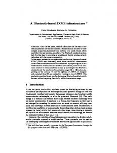
2 The dual-radio based scatternet The most significant part of the NXT robot building set is the main brick that contains the central microcontroller, several IO ports and the Bluetooth unit (CSR BlueCore 4 v 2.0) controlled by an ARM7 chip. The radio coverage is guaranteed up to ten meters. The point-to-point Bluetooth communication is implemented using the Serial Port Profile (SPP) [32]. By the means of the previous section our first goal is to create a communication unit equipped by two independent Bluetooth radios. The NXT is not a skeleton system i.e. it is not possible to extend the original electronics of the central brick. That is why we invented an unusual solution, the basic idea of which is that two central bricks are connected to each other through their RS485 ports. These ports regularly serves as a receiver of measured data from various sensors of NXT standard, however, they can not only receive but also send data via the NXT sensor cable. Using this capability of the RS485 ports, a fast half-dulpex communication link can be established between the two bricks. Thus, the two bricks form a new autonomous unit that has two independent radios (each in its own host brick). The point-to-point communication or on the Bluetooth either on the RS485 link must be controlled by program codes in the application layer. In the present project, we applied the C-like NXC programming language of the NXT microcontroller, which contains API functions to treat the ARM7 controller and the RS485 port. (The Java-like Lejos or the assembler-like NBC programming tools are also capable for the purpose.) Each of the radios of the autonomous unit can be either master or slave in the piconet it belongs to. Every unit with the two radios is a connection point between the two piconets, so such units can form a large connected network. Let us represent this network by a directed graph, where the nodes correspond to the autonomous units and the directed links denote the Bluetooth connections so that the direction is from the master to the slave (see Figure 1). It is also possible to involve Bluetooth equipped cell phones into this network, however the cell phones must be end-points (leafs) of the graph since a phone has only one Bluetooth radio. With the help of this multi-hop network, the cell phones can communicate with each other so that in this scenario, the cell phones are the clients and the mobile robots provide service for them. Various self-assembly algorithms to create such networks are detailed by Sohrabi et al. [28] for sensor nodes with fixed spatial positions. The situation is much more difficult when the nodes are mobile robots or cell phones carried by their owners, since the topology is continuously changing. In that case a continuous maintaining the network connectivity and routing information is necessary. Working out such connectivity preserving and routing algorithms is beyond the scope of the present work. Our aim is to implement a real communication capability test for a simple topology consisting of several autonomous NXT robots assembled by the scheme above. This communication test is described in the next section.
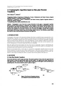
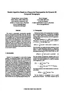
3 The communication tests and results The test presented here is based upon variable number of robots arranged in a linear graph topology shown by Figure 2. In order to get a picture about the communication speed a simple ping application was written. In this application, the first robot in the chain sent small (16 bit long) ping packets into the chain, while the robot on the other end of the chain replied automatically the ping packets. A ping procedure sent ten packets in one series. The next packet was sent as soon as the acknowledgement arrived. The average reply times were measured and recorded for various robot chain lengths of N = 3, 4, 5, 6 and 7. For each chain-length, five ping procedures were executed. The average reply times are shown in Figure 3. It can be seen that each robot-robot link rises the hopping time by approximately 60 milliseconds, since the average reply time is the double of the average hopping time. It is also important that the experiments were executed in a closed room with solid walls the diameter of which was less than ten meters that is each Bluetooth radio was within the coverage of all of the others. In spite of this closeness, the possible interference did not caused increasing latency with the increasing chain-length. This is mostly due to that the ping packets were short and only one packet were traveling on the chain at a time.
4 4.1
The area exploration algorithm The cell-grid and the radio coverage
The area to be explored is divided into non-overlapping equally sized square-shaped grid cells as it is usual in such problems. In our case, the cell size depends on the Bluetooth communication range. The specific task of the team is to visit all of the cells in the area and discover the possible obstacles. A practical application of this task, for example, is the case when the team has to find the locations of several objects or connect to a freshly discovered Bluetooth equipped host (e.g. cell phone) in order to establish a wireless multi-hop communication chain between the host and the base station. The only restriction is that the robots have to keep up the linear fixed-topology communication chain between the base station and the robot farthest from the base station (measured along the chain). In such tasks one of the most important parameter is the radius of the radio coverage of a robot. We denote this by rcov and suppose that the radio contact of two robots within the coverage of each other is guaranteed. In several papers, however, more additional environments are defined beyond rcov [6, 21, 33]. One of these is a so called “precaution” or “safety” environment (here denoted by rsafe), the radius of which is smaller than rcov . The basic idea in this is that the algorithm tries to keep each robot in the
safety environment of its neighbors, which greatly increases the robustness of the connectivity of the team. In the present paper, the idea of the safety environment is also employed, though its role will be a bit different. In our scheme, it can happen that a robot leaves the safety environment of its neighbor if an unforeseen obstacle blocks a planned move. However, the algorithm guarantees that no robot can leave the radius coverage of its neighbors under any circumstances. First, we give the actual parameter values of rcov and rsafe in cell size units C, which is defined as the side of a square cell. Then, based on the radius of the actual Bluetooth coverage the specific value of C can be given. Here the two environment parameters are chosen to be:
rsafe =
3 2C 2
and rcov =
26 C 2
(1)
Let a cell position (P) be given by the Cartesian coordinates of the centre of the cell. Based on the radii given above we define the environments ES(P) and EC(P) of a certain cell P as the sets of cells that are completely within the circle centered in P with the radii rsafe and rcov , respectively, as it is demonstrated in Figure 4. In addition to these the environment EN(P) of P is also defined as the union of the cell P and all of its side neighbors (see Figure 4). These environments will be important in the exploration algorithm. EC(P) is the set of cells where the wireless connection is guaranteed with a robot located in P. ES(P) is the set of cells where the communication neighbors of the robot in P are planned to be after finishing a team move. Finally, EN(P) is the set of cells where a robot in P can move to during a team move. This means that during a team move a robot is allowed to move no farther than a neighboring cell. Note that P is element of EN(P), that is, a robot can also stay in place in a team move. Besides, the movement of each robot is controlled so that its destination point is located in or very close to the centre of the destination cell. 4.2
The communication chain
As it was mentioned in the introduction, here the simplest topology was chosen for the communication network: a linear chain (without branches and loops). In addition to this, the topology is static, that is, the established radio connections cannot be broken and no new connections are established. Therefore the communication scheme is quite simple: at one end of the chain is the base station fixed in a centre of a cell (this is the origin), and every robot has two communication neighbors except the last one. If, for example, the base station has a broadcast message for the team then it sends the message to its communication neighbor robot, and the message gradually propagates to the last robot in the chain. If a chain member has a unicast message to a specific member then the message passes through the stations only between the source and the destination members. 4.3
The wall-like obstacles
The area to be explored is supposed to contain unknown wall-like (boundary-like) obstacles. The definition of such an obstacle is simple: if it is possible for a robot to move from a given cell to a neighboring cell then there is no obstacle on the boundary between the two cells, otherwise the common side of the two cells is considered to be a wall-like obstacle. Any segment of the cell grid can be an obstacle (wall), since we do not have a priori knowledge about the situation or the density of the obstacles. A wall-like obstacle can be identified by giving the positions of the two cells the boundary of which is blocked by the obstacle. We assume that an obstacle is discovered by the robot-team only if a robot tries to move from one cell to a neighboring one. This assumption is realistic for many types of small mobile robot because in our scheme a robot is generally situated in the centre of a cell i.e. a few meters from the cell boundary, and from this distance it is generally impossible to determine if the centre of the neighboring cell is reachable or not. Even if there is an object that seems to be an obstacle for the robot in a few meters distance, there can be gateway(s) discoverable only by a systematic search along the blocking object. This definition of the obstacles implies the least loss of generality. 4.4
The exploration algorithm
Let us introduce the following notations: §
The members of the robot team are denoted by Ri, where i = 1,..N. The communication neighbors of Ri are Ri-1 and Ri+1 (if they exist), R1 represents the host in the base station, RN is the robot farthest from the base station on the communication chain.
§
The cells occupied by the robots are given by the set of vectors {P1, … PN}. With P1 = (0,0) , which is the position of the base station.
§
In each team position {P1, … PN} the algorithm determines the next team-position {P’1, … P’N}. Therefore, an elementary move of the robot Ri is given by the vector (P’i – Pi).
The applied area exploration algorithm has to guarantee the connectedness of the linear communication chain and find the best possible exploration move. The proposed algorithmic scheme divides the robot team into a leader and follower robots as follows: §
The robot RN is appointed as the leader of the team. This means that in a step cycle the elementary move for RN is calculated first. Similarly, to the other referred methods, the basic concept of this calculation is the utilities of the possible moves, which are determined by the relative position of RN and the frontier cells.
§
The moves of the other robots (R1… RN-1) are calculated to guarantee the connectedness. Let us call them follower robots. However, their task is to not only ensure communication, but also explore new cells, which has not been visited before. This “secondary” task is done automatically meanwhile their primary follower movement. The exploration movement of RN
is controlled by the possible moves of the follower robots: if an exploration move cannot be followed, then this move will be forbidden for RN . The next position of the team is calculated in a recursive way. First, the set of possible new positions for RN is determined and arranged in a priority order. (Let us call this ordered set of positions as Priority List of New Positions and denote it by PLNN.) Then the algorithm examines the first element of PLNN whether it is possible for RN-1 to follow this step. This is done by determining the PLNN-1 for RN-1. If this is empty the move P’N - PN is not possible and the next element in PLNN is examined in the same way. If PLNN-1 is not empty then the same is done, that is, the first element of PLNN-1 is examined whether it is acceptable for RN-1; if it is not then the procedure takes the next element in PLNN-1. So the same method is repeated at each level from N down to 1, where the i-th level corresponds to examinations of the elements in PLNi. This recursive method continues until an acceptable new position is found in PLNN, which means that an acceptable new position is found for each robot. This method also ensures that the best possible team-move is found, provided that each PLNi is ordered from an optimality point of view. This recursive scheme can be well represented by a decision-tree with N-1 hierarchy levels. Here the highest hierarchy node and its outgoing edges correspond to the leader robot and the possible new positions in PLNN so that the edges are arranged in priority order from left to right (see Figure 5). The next hierarchy level represents the possible new positions in the PLNN-1 and so on. Finally, the leaves of the tree correspond to (completely given) new positions of the team, where the leftmost node is considered to be the most optimal position for the team (provided that the better position have higher priority in each PLNi). However, not every new position is possible; some of them are forbidden by obstacles or the danger of breaking up the communication chain. The recursive algorithm described above finds the leftmost possible (i.e. not forbidden) team-position. The determination of the whole planned team-position can be given in a concise way by the following recursive function
(
)
Team _ New _ Position i, [Pi'+1 ... PN' ] =
[
(
ì Pi' , Team _ New _ Position i - 1, [Pi' ... PN' ] ï =í ï [ (0,0) ] or [ ] , if i = 1 î
) ] or [ ] if
i >1
(2)
where [P’i+1 … P’N ] are the planned position of Ri+1 … RN, and P’i is the first position in PLNi for which the Team_New_Position( i-1, [P’i … P’N ] ) function call returns a nonempty list. If there is no such an element in PLNi the function returns also an empty list. Thus, the function call Team_New_Position(i,[…] ) always returns a position list of length i, and this list increases by one
new position in each recursive cycle. It can be seen that the function call Team_New_Position(N-1, [P’N]) returns an entire planned follower team-position [P’1 … P’N-1 ] if it exists for P’N , or an empty list, otherwise. The algorithm of the recursive function Team_New_Position() are detailed by Algorithm 1. It can be seen that there is yet an additional element in this algorithm: in order to return a nonempty list of new positions the condition PLN(j) Ï {P’2 , … P’i-1 , P’i+1 , … P’N} \ {(0,0)}
(3)
must be also true. With other words this means that the possible new position PLN(j) can be selected only if it is not coincides with the other possible new positions of the fellow robots except the base station (0,0). Since this condition is examined in all levels (i.e. for all values of the index i), the entire planned new team-position will have this property, that is, no new robot-position will coincide with any other except in the base station. This property is very useful from collision avoiding point of view, because it effectively keeps the robots in a cell-size distance from each other. To be more specific, two robots may arrive into the same cell only if one of them encountered a new obstacle and could not accomplish the planned move. However, no three or more robots can arrive in the same cell. The only exception is the base station (0,0), where a much more advanced robot navigation system is supposed than in the area outside (see for e.g. [15]). The main exploration algorithm is given in Algorithm 2. First the list PLNN is generated by the Priority_List_of_New_Positions(N) function call, and then the algorithm examines each possible new position in PLNN in priority order if it can be competed to an entire team-move. This is done by calling the function Team_New_Position ( N-1 , [PLNN(j)] ). The object called Map contains all information that the robot team gathered about the explored area. The leader robot registers into its Map not only the real obstacles encountered by the team but also “virtual obstacles”, which plays important role in the whole exploration algorithm. These virtual obstacles are considered as real ones in the Manhattan path finding procedure (see later) of the leader robot. The registration of a virtual obstacle is implied by two different events: firstly, if RN finds move in its PLNN that would take it outside the EC environment of RN-1 (denoted by EC(PN-1)) then blocks that move by a freshly registered virtual obstacle and substitutes the proposed position by PN in PLNN, i.e. a null move for RN. Secondly, if the function call Team_New_Position ( N-1 , [PLNN(j)] ) returns an empty list for the element PLNN(j) of PLNN then also a virtual obstacle is registered into Map between the positions PN and PLNN(j). Actually, a virtual obstacle refers to the fact that the chain-like team cannot reach a specific cell with the help of a specific move. This cell, however, may be reached later from a different direction. In the next team-move planning cycle the possible new positions of RN blocked by virtual obstacles will not be selected into PLNN. Without the application of the virtual obstacles, the team would keep trying to reach these presently “unreachable” cells not realizing the hopeless situation. It should be noted that
the virtual obstacles blocks only RN, the other robots are blocked by only the real obstacles. The real obstacles explored before are taken into consideration when the robot Ri calculates its PLNi. A robot may discover unexplored obstacles only when a team move is calculated and the “start move” procedure launches at the individual robots. Therefore, it is not sure that a planned team-move can be realized. If a robot cannot enter into an adjacent cell because of a “real” freshly discovered obstacle then it stays in its present cell, say, in the centre of the cell. If the function call Priority_List_of_New_Positions(N) does not yield any exploration move (returns an empty list) in the beginning of the algorithm, then the move takes a backtrack move (denoted by Backtrack Team-Move in the algorithm). This is necessary, because in this case the leader robot is completely closed into an explored area by virtual or real obstacles, and only the backtracking solves the situation. Rooker and Birk also employ this method in [20]. If no backtrack is possible, i.e. we are back in the original position, then all virtual obstacles are deleted and the exploration continues. At the end of the moving phase, the robots, one after other, broadcasts their new positions and the possibly discovered obstacles. It is enough to give their new positions relative to the previous one, so one of the five possible moves (the four directions plus the null move) is given. This information, together with the possible existence of the obstacle, can be encoded in four bits (or in one byte for the sake of simplicity); therefore, each robot sends only one byte in a step-cycle. A crucial element of the algorithms above is the Priority_List_of_New_Positions() function, which constructs the PLNi of the individual robots and is different for RN and Ri (i