The main idea of the paper is a network coding-based approach that marks pack- ... In this paper, we propose a marking scheme (PPM+NC) that is inspired by ...
A Network Coding-Based Approach to Probabilistic Packet Marking Pegah Sattari, Minas Gjoka, Athina Markopoulou EECS Department, University of California, Irvine Email: {psattari, mgjoka, athina}@uci.edu
Abstract Traceback schemes aim at identifying the source(s) of a sequence of packets and the nodes these packets traversed. This is useful for tracing the sources of high volume traffic, e.g., in Distributed Denial-of-Service (DDoS) attacks. In this paper, we are interested in Probabilistic Packet Marking (PPM) schemes, in which intermediate nodes probabilistically mark packets with information about their identity and the receiver uses information from several packets to reconstruct the paths traversed by these packets. The main idea of the paper is a network coding-based approach that marks packets with random linear combinations of the router ids instead of individual router ids. We show that this approach decreases significantly the number of packets required to reconstruct the attack paths. We also show that it is implementable in practice using a small number of under-utilized bits on the IP packet header; our proposed practical scheme optimizes the tradeoff in the bit-budget allocation, naturally raised by the network coding marking approach, and reconstructs the attack graph with low computational complexity, high accuracy and low delay. We also combine the network coding marking approach with adjusting the marking probabilities of different routers and show that this further improves the performance. Along the way, we accurately model the performance of our proposed as well as of prior PPM schemes based on the coupon collector’s problem with unequal probabilities. We show the significant benefit of our proposed schemes through comparison to several baseline schemes, under the same bit-budget, and considering various attack topologies. The ideas of network coding-based marking and adjusted marking probabilities are orthogonal to and can be combined with several existing PPM schemes to improve the overall performance. Key words: Network Coding, Network Measurement and Inference, Network Security, Distributed Denial-of-Service Attacks, Probabilistic Packet Marking
1
1
Introduction
Distributed Denial-of-Service (DDoS) attacks are one of the hardest problems on the Internet today. During a DDoS attack, a large number of compromised hosts coordinate and send unwanted traffic to the victim thus exhausting the victim’s resources and preventing it from serving its legitimate clients. In particular, during bandwidth flooding attacks, a large number of attack flows flood the victim’s access link with unwanted traffic. Victims of DDoS attacks include e-commerce, news, banks, government and other public-access websites and the results include financial, operational and political damage to companies, organizations and critical infrastructure. Classification and surveys of DDoS attacks and defense mechanisms can be found in [11, 25]. Several approaches have been proposed to deal with flooding attacks. In this work, we focus on IP traceback mechanisms that address one aspect of the problem: tracing the attack back to its source(s). Traceback in itself does not stop an attack but is an important component in a bigger defense system, when combined with additional mechanisms such as intrusion detection, filtering for blocking unwanted traffic, etc. There is a large literature on IP traceback schemes, as surveyed in [3]. In this work, we are particularly interested in the family of multi-packet Probabilistic Packet Marking (PPM) schemes, which got introduced in [32] and evolved into a number of improved marking schemes [1, 2, 10, 15, 17, 23, 24, 28, 34, 36–38]. According to the PPM approach, packets are marked probabilistically with information about the IP addresses of the routers they traverse. The victim then uses the information in the marked packets to reconstruct the addresses of the routers traversed and trace the attack back to its sources. In this paper, we propose a marking scheme (PPM+NC) that is inspired by the recently emerged field of network coding [13, 14, 21]. The main idea is the following: if we mark packets with random linear combinations (introduced in the context of network coding in [19]) of the router ids, instead of marking them with the individual router ids (as it was the case in traditional PPM), then the number of packets needed to reconstruct the attack paths can be significantly reduced. This benefit can be theoretically explained by the fact that probabilistic traceback is essentially a coupon collector’s problem [26, 32], which has been recently shown to benefit from the use of random linear network coding [9, 14]. We also propose a practical scheme (which we call practical PPM+NC) that implements the above idea using a limited number of under-utilized bits on the IP header for marking. Furthermore, the proposed practical scheme has several attractive properties: (i) it allocates the bit-budget optimally between the coefficients and the linear combination in the marking field, i.e., it optimizes the core tradeoff naturally raised by the network coding marking approach and (ii) it reconstructs the attack graph with low computational complexity, high accuracy and low delay. The idea of network coding-based marking can be combined with several existing PPM approaches to improve the overall performance. There is a large literature on PPM, trying to improve the tradeoff between the number of bits used in the packet header and the number of packets needed to reconstruct the path [1]. Some papers achieve this goal 2
through the content of the marks: they reduce the number of bits by using fragments [32] or hashes [34] instead of the entire IP address, or algebraic coding ideas [8]. Some others, such as adjusted PPM [23,28,37], achieve their goal by focusing on an orthogonal aspect: adjusting the marking probability at each router depending on its position in the attack path. We compare our practical PPM+NC scheme to the former approaches, for the same bit-budget used for marking. We also combine the network coding-based marking with adjusting the marking probabilities into an adjusted practical PPM+NC scheme, and show that this further improves the performance. We evaluate the proposed schemes through analysis and simulation and we compare them to appropriate baseline mechanisms for various topologies of attack graphs. The results show that everything else (i.e., bit-budget and other practical considerations) being equal, the network coding schemes significantly reduce the average number of packets needed for reconstruction. Along the way, we also make some side contributions. We provide performance models, based on the coupon collector’s problem with unequal probabilities, that accurately capture the performance of the proposed as well as of prior PPM schemes. We also revisit the adjusted PPM [23, 28, 37], which has been treated heuristically so far, we analyze it as a coupon collector’s problem and combine it with the network coding-based marking. The rest of the paper is organized as follows. Section 2 summarizes related work. Section 3 presents the proposed network coding-based scheme (PPM+NC) and evaluates it through analysis and simulation for single and multi-path scenarios. In particular: Section 3.1 revisits PPM as a coupon collector’s problem; Section 3.2 presents the key idea of network coding-inspired marking PPM+NC; Section 3.3 discusses the bit and other constraints faced in practice; and Section 3.4 presents the practical PPM+NC scheme, which implements the network coding marking idea while at the same time addressing the practical considerations. Section 4 revisits the orthogonal aspect of adjusting the marking probability [23, 28, 37] and combines it with the network coding-based marking in an adjusted practical PPM+NC scheme. Section 5 provides comparison of the proposed schemes against several well-known baselines schemes, for different topologies, using simulation and analysis. Section 6 concludes the paper.
2
Related Work
There is already a large body of literature on IP traceback [3]. In this paper, we are interested in Probabilistic Packet Marking (PPM) schemes, and particularly, in multi-packet probabilistic marking. This is in contrast to the single-packet IP traceback approach, proposed in [33], which used router state to track the path of a single packet, but required routers to keep a large amount of state. Bellovin [4] introduced ICMP traceback, in which each router samples, with low probability, one of the packets passing through it and sends an ICMP traceback message including the contents of the sampled packet and information about the adjacent routers along the path to the destination. Burch et al. [6] proposed controlled flooding, in which 3
the victim reconstructs attack paths by selectively flooding network routes and observing the change in traffic from the attacker. They also mentioned the idea of marking packets for IP traceback, either probabilistically or deterministically, with IP addresses of routers they go through. Savage et al. [32] presented the realistic design and implementation of PPM and proposed the Fragment Marking Scheme (FMS), taking into account the limited number of bits available for marking on the IP header. According to FMS, each router’s IP address and redundancy information is divided into eight 8-bit fragments and the router probabilistically marks a packet with one of these eight fragments selected at random. This approach works well for a single attacker, but suffers from high computation overhead due to the need to check a large number of combinations of fragments as well as a large number of false positives in distributed attacks [34]. The vulnerabilities of distance-indexed probabilistic marking schemes have been discussed in [7] and some remedies have been proposed to mitigate them to a certain extent. In Section 5.1, we discuss FMS in more detail, and compare it to our proposed practical PPM+NC scheme. Song et al. [34] improved the computational efficiency and accuracy of reconstructing the attack paths under large scale DDoS by introducing an Advanced Marking Scheme (AMS); they also introduced an authenticated scheme to deal with spoofing from compromised routers. They made the assumption that the victim has prior knowledge of the upstream router topology by using the traceroute tool. The goal is then to infer which paths on this map are traversed by the attack traffic. Yaar et al. [38] proposed Fast Internet Traceback (FIT) which is similar to the AMS scheme in the use of the upstream router map and in the packet marking format, but it obtains the upstream router map using packet markings rather than the traceroute tool. They also use a single bit along with a TTL modification for the distance value and node sampling instead of the commonly used edge sampling; they exploit the fact that packets that traverse the same path during a TCP connection can be grouped together by the victim. We further discuss and utilize their distance mechanism and map generation technique in Sections 3.3 and 3.4. Also, in Section 5.2, we discuss AMS in more detail, and compare it to our proposed Hashing+NC scheme. Dean et al. [8] proposed an algebraic traceback approach which encodes the information of the nodes in the path as points on polynomials. Their scheme improves robustness both for noise elimination and multi-path reconstruction. However, the number of packets required to reconstruct the path is high. In Section 5.3, we analyze the algebraic approach in detail and compare it to our proposed PPM+NC approach. Goodrich [17] presented another PPM based traceback approach, called randomize-andlink. The main idea is to have each router mark with a random fragment of its message together with a large checksum cord on its entire message. The scheme does not require a prior knowledge of the topology, but since it does not use a distance field, it faces problems in reconstructing the attack graph under large scale DDoS attacks. Park et al. [27] and Adler [1] studied tradeoffs for different parameters in PPM. In par4
ticular, Adler studied the tradeoff between the number of bits used for marking and the number of packets required for reconstruction, provided a theoretical analysis, and proposed a one-bit marking scheme. However, this work does not scale to large DDoS attacks [38]. Dong et al. [10] introduced Efficient PPM which also uses a single PPM bit, but decreases the number of packets significantly.
In [35], a scheme that combines tracing and defending was proposed. Tseng et al. [36] proposed an improvement of PPM with non-preemptive compensation, which uses counters at routers to make the probability that a marked packet is received by the victim equal to the marking probability. Aljifri et al. [2] proposed a scheme to reduce the number of packets required for path reconstruction using compressed IP headers.
Wei and Ansari [37] proposed to adjust the marking probability from the perspective of service providers. In a similar spirit, Peng et al. introduced the Adjusted PPM (APPM) scheme [28] to reduce the total number of required packets by using a higher marking probability for routers closer to the attacker. The idea was to remove the bias in favor of routers closer to the victim, and receive an equal number of packets marked by each router on the attack path; they heuristically set the adjusted marking probabilities to achieve that goal and proposed three schemes to make APPM practical [28]. The main problem with that approach is that each marking router needs to know its position in the attack path. This is difficult in practice, but some techniques have been proposed [23,37]; in particular, [23] proposed to use the TTL value in the IP header. We will further discuss this issue in Section 4.1. The effectiveness of APPM was analyzed by Rizvi et al. [29] using the analysis similar to that in [27]. They showed that APPM is also subject to spoofing of the marking field especially for shorter attack paths. They proposed a modified version of the third scheme in [28] to reduce the number of unmarked packets the victim receives. In Section 4, we discuss in detail the APPM scheme, analyze and extend it.
Gao and Ansari [15] proposed Autonomous System-based Edge Marking (ASEM): a practical and robust inter-domain marking scheme at the AS level rather than hop-by-hop. Ma [24] introduced the Tabu Marking Scheme (TMS), in which a router regards a packet marked by an upstream router as a tabu and does not mark it again. TMS has the same convergence time as overwriting PPM schemes under single-path attacks, but it reduces the convergence time under distributed attacks. Since overwriting of previous marks is not allowed, TMS is vulnerable to spoofing by the attacker in practice.
In this paper, we exploit the insight that network coding makes the coupon collector’s problem easier, considering all router ids as a set of coupons. Therefore, our contribution is orthogonal to and can be combined with previous PPM approaches. 5
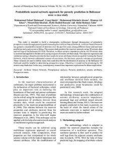
A
d
d-1
Pm(d) Pm(d-1)
3
2
1
Pm(3)
Pm(2)
Pm(1)
V
Fig. 1. PPM over a single path with d routers between the attacker A and the victim V .
3 3.1
PPM+NC: a Network Coding Based Approach to PPM Traceback as a Coupon Collector’s Problem
Consider the single path of length d shown in Fig. 1. Attacker A sends packets towards the victim V . In the basic PPM approach, each intermediate node i along this path marks the packet with its IP address, with marking probability Pm (i). Ideally, we would like to have every router on the path append its own IP address, so that the packet contains the entire path when it arrives at the victim. Unfortunately, this would require a large and variable number of bits on the IP header, and is therefore infeasible. In contrast, the probabilistic packet marking (PPM) approach, introduced by Savage et al. in [32], requires space only for one mark on the header and has the routers probabilistically mark packets going through them. Each router (i) makes an independent decision about whether to mark a packet, with marking probability Pm (i), or not. If it decides to do so, it overwrites any previous marks. As a result, every packet finally contains at most one router’s mark after traversing the entire attack path. Let us call perceived probability the probability that a packet still has the mark of router i when it arrives at the victim: Q Pp (i) = Pm (i) · j=i−1 j=1 (1 − Pm (j)). The marks on the received packets allow the victim to sample the routers on the path. After receiving a sufficient number of packets, X, the victim can recover the ids of all routers on the path. Notice that X ≥ d because many marks may be duplicates and thus carry no new information. Traceback as a coupon collector’s problem. Early on [26, 32], it has been observed that PPM is essentially a coupon collector’s problem [12]. In the classic coupon collector’s problem, there is a collection of n coupons; coupons are placed randomly in boxes; a collector gets one box at a time until she completes the full collection of n coupons. If all coupons are equally likely, each with probability p = n1 , then the collector needs to get n ln n + Θ(n) coupons on average [26]. In [32], it was assumed that all routers mark with the same probability (i.e., Pm (i) = p, ∀1 ≤ i ≤ d). An upper bound for the average number of packets the victim needs to collect, to reconstruct a path of length d, was given in [32] and used in subsequent papers: E[X]
t) as in [30]. In this paper, we omit such analysis and focus on the E[X] performance metric. Key Ideas and Rationale. Our objective in this paper is to decrease E[X] by tuning parameters that can affect the behavior of PPM as a coupon collector’s problem with unequal probabilities. In particular, there are two orthogonal aspects we have control over: the content of the marks and the marking probability. • The main idea is to mark packets with random linear combinations of the router ids, instead of individual router ids; the same idea applies to hashes and fragments as well. Recent developments in network coding [9, 14] showed that E[X] in the coupon collector’s problem (with equal probabilities) can be reduced from Θ(n ln n) to Θ(n) by storing random linear combinations of coupons in the boxes instead of the coupons themselves. We apply this idea in the traceback context (PPM+NC) in Section 3.2, and present a practical implementation, when the bit budget is limited, in Section 3.4. • The second idea is to optimize the marking probability. We build on the idea of APPM which makes the perceived probabilities equal for all routers, i.e., Pp (i) = d1 , i = 1...d, by appropriately tuning the marking probabilities Pm (i) depending on the position of the router i in the attack path. In Section 4, we combine the two ideas in the adjusted practical PPM+NC scheme to further improve the performance of practical PPM+NC. Along the way, we prove that APPM minimizes E[X] (as opposed to heuristic approaches so far) and we extend this approach to the multi-path scenario. 7
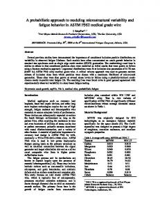
linear combination
random coefficients
c1 c2
∑ci.IDi
ck
Fig. 2. The marking field on the IP header in the PPM+NC approach. IDi is the entire IP address of router i. ci is the coefficient that router i has chosen uniformly at random out of a field F2b .
At the same time, we provide analytical models that accurately capture E[X] of the proposed as well as of prior baseline schemes. Other performance metrics of interest discussed throughout the paper include the number of bits used for marking and the overhead at the routers (e.g., due to computation and special processing of marked packets). We make some standard assumptions for the PPM problem [32]: (i) attackers may send any packet; (ii) multiple attackers may act together; (iii) attackers may be aware of the traceback scheme; (iv) attackers send a large number of packets; (v) routes between hosts are fairly stable. 3.2 PPM+NC Idea: Marking with Random Linear Combinations In the classic coupon collector’s problem [12], it is well-known that the first coupons we collect are innovative (i.e., not identical to coupons already collected), but as we collect more coupons, it becomes harder to find innovative coupons and most of the time ends up being spent on collecting the last few coupons. Recently, it has been observed that network coding can help with this problem [9, 14]. If each box contains random linear combinations of coupons, instead of individual coupons, we can reconstruct the n unique coupons when we receive n independent linear combinations and solve a system of linear equations. The intuition is that each box is more likely to bring some innovative information and therefore to be more useful. In [9], it has been proved that, in the case of n equally likely coupons, the average number of coupons E[X], which needs to be collected to get the entire collection, decreases from Θ(n ln n) in the original problem to Θ(n) when random linear combinations are used. This intuition has also been recently used in Avalanche [16], a peer-to-peer system in which peers forward random linear combinations of blocks of a file, instead of the blocks themselves, thus decreasing the download time. The use of random instead of deterministic linear combinations is not necessary in order to harvest the benefit of mixing information into a linear combination; however, it makes distributed implementation easy, which is important when coordination between network entities (in our case routers) is difficult. As we already discussed, PPM is also a coupon collector’s problem, albeit not necessarily with equal probabilities, and therefore can also benefit from this network coding idea. We propose the PPM+NC scheme that combines random linear network coding [19, 20] with PPM. In this approach, every router i decides to mark a packet with probability p. 8
Once it decides to do so, it chooses a coefficient ci randomly out of a field F2b , multiplies its IP address IDi with the coefficient, and adds the result to the current content of the marking field. In order to demonstrate the basic idea of PPM+NC, we first assume that there is enough space on the header for routers to mark with the entire 32-bit IP address, or linear combinations of IP addresses. In Sections 3.3, 3.4, and 5, we consider the bit limitations and other practical constraints. Part of the marking field on the header is dedicated to store a certain number k of coefficients ci , and another part to store P the linear combination i=k i=1 ci · IDi , as shown in Fig.2. Note that all the additions and multiplications for the linear combination are performed over a field of appropriate size which will be discussed in more detail later. Our goal is to recover the IP addresses of the routers from the observed marks in the packets; the reconstruction process is similar to solving a system of linear equations, which is possible when the victim receives enough packets to obtain a full rank matrix. To analyze PPM+NC in the single path scenario of Fig.1, we observe that: Pp (i) = Pm (i) · p(success) where p(success) is the probability of obtaining a full rank matrix out of the linear combinations the victim has received. Ho et al. provided a lower bound on the probability of choosing linearly independent combinations as a function of the field size 2b [19, 20]. 1 In particular, the upper bound on the probability of failure is proportional to the inverse of the field size and can be made arbitrarily small by choosing P a sufficiently large finite field. In the traceback problem, observing a mark i=k i=1 ci · IDi at the victim is equivalent to choosing a random linear combination of the router IDs. For a long path, it is unlikely to obtain dependent linear combinations of routers’ IP addresses from different packets, even when the coefficients at each router are chosen out of a small field. Therefore, in our case, p(success) ' 1. If, in addition, the same marking probability is used on all routers (i.e., Pm (i) = p, ∀i), then Pp (i) ' p is a good approximation of the perceived probability of router i’s mark in the PPM+NC scheme. Therefore, we can use Eq.(2) with n = d and pi = p to model the proposed PPM+NC scheme: E[X] =
Z ∞ 0
(1 −
d Y
(1 − e−px ))dx
(4)
i=1
Fig.3(a) and Fig.3(b) demonstrate that the analytical calculations (Eq.(3) and Eq.(4) for the PPM and PPM+NC schemes respectively) agree perfectly with the simulation results for a single attack path. These figures compare the PPM+NC scheme to the PPM scheme in terms of the average number of packets required to reconstruct the attack path and demonstrate that PPM+NC significantly outperforms PPM, i.e., E[XP P M +N C ] < E[XP P M ], especially for 1
E.g., in a multicast setting on an arbitrary network with independent or linearly correlated sources, and a network code with coding coefficients chosen independently and uniformly at random from the elements of a finite field Fq , the probability that all N receivers can decode the source processes is at least (1 − Nq )ν , q > N , where ν is the number of links with associated random coefficients.
9
250
400 simulations PPM model PPM simulations PPM+NC model PPM+NC
Average number of packets
Average number of packets
200
simulations PPM model PPM simulations PPM+NC model PPM+NC
350
150
100
300 250 200 150 100
50
50 0
0
5
10
15 20 Path length
25
30
0 0.01
35
(a) Varying path length d. The marking probability (same on all routers) p is 1/25.
0.015
0.02 0.025 0.03 Probability of marking the packets
0.035
0.04
(b) Varying marking probability p (the same on all routers). The path length d is 14.
Fig. 3. Comparison of PPM+NC to PPM via both simulation and analysis in terms of the average number of packets needed to reconstruct a single path (of length d and using the same marking probability p on all routers of the path). Each point is averaged over 500 realizations. A field of size 22 was used for operations.
longer paths. Fig.3(a) considers paths of varying lengths (1 to 31 hops, which is the case for most Internet paths [32]) and the marking probability p is the same on all routers and set to 1/25. Fig.3(b) considers a fixed path length (d = 14) and various marking probabilities in the range [0.01 − 0.04]. We have considered the condition p ≤ d1 as in [32] for minimizing the bound in Eq.(1). As mentioned above, the coefficients for PPM+NC can be selected even from a field of a small size without significantly reducing the probability of obtaining an independent equation p(success). Here a very small field of size 22 was sufficient, as shown in Fig.3. Therefore, unless otherwise stated, we have chosen a small field of size 22 in all our experiments on the PPM+NC scheme in this paper. Dealing with Multiple Paths. So far, we have discussed marking over a single path. However, during a distributed attack, several attack sources flood the victim through different attack paths that eventually form an attack tree with leaves being the attackers and root being the victim. Fig.4 shows a simple distributed attack model as a full binary tree in i=4 which nodes {Ri }i=7 i=1 represent the routers and {Ai }i=1 represent the flooding sources. For any internal node {Ri }, we refer to its parent (neighbor closer to the victim) as downstream neighbor and to its children (neighbor closer to the attack sources) as upstream neighbors. Each attack packet comes from one possible attack source and reaches the victim through a unique path on the attack graph. Each attack source {Ai } is located at a leaf node and the attack path from {Ai } is the ordered list of routers between {Ai } and V that the attack packet has gone through. The PPM+NC marking scheme can easily be extended to the distributed scenario by simply considering the attack tree as a collection of several independent paths, each of which starts from a different attacker and goes to the victim. Therefore, once a router 10
A2
A1 R4
R5 R2
A3
A4
R6
R7 R3
R1
V
Fig. 4. Example of an attack tree, with 7 nodes and 4 attackers flooding the victim V .
in the selected attack path decides to mark the packet, it acts similarly to a router in a single path attack scenario. We can analyze both PPM and PPM+NC schemes in an attack tree by replacing appropriate values of pi in Eq.(2). Let Ni be the number of attack paths going through router i and Ntotal be the total number of attack paths in the tree. Assuming that all attack sources send at the same rate (i.e., are equally likely), the probability of a packet going through router i is Ni /Ntotal . (Different rates can be taken into account when calculating the probabilities of a packet going through different paths.) We can write for the Q PPM scheme: pi = Pp (i) = Pm (i) · j∈S (1 − Pm (j)) · (Ni /Ntotal ) where S is the set of all downstream routers in the path from i to the victim. If router i is in layer li of the tree, where li = 1 is the closest layer to the victim, then S will consist of li − 1 routers. For the PPM+NC scheme, we can write: Pp (i) = Pm (i) · p(success) · (Ni /Ntotal ), where p(success) is the probability of obtaining a full rank matrix out of the linear combinations received by the victim. Pm (i) = p and similarly to the case of a single path attack, p(success) ' 1. In Section 5, we test our proposed schemes on realistic topologies as well as m-ary trees.
3.3 Practical Constraints Let us now discuss some constraints that arise in practice and must be taken into account in designing a practical PPM+NC scheme. I. Bit budget. The most important constraint is the number of bits in the IP header that we use for marking. Typically, traceback approaches use some, currently under-utilized, bits in the IP header: at least the 16 bits of the IP identification field, as in [32], or at most 25 bits (including the 8-bit TOS field and the unused fragment flag, in addition to the 16-bit identification field) as in [8]. It is clear that the basic PPM+NC idea described in the previous section, which marks with linear combinations of the entire router 32-bit IP addresses, will not work under this constraint. Recall that the marking field in the PPM+NC approach has two parts: one dedicated to store a predetermined number k of coefficients ci , randomly chosen by some routers i with IP addresses IDi ’s, and another P to store their linear combination i=k i=1 ci · IDi . It is clear that even a single IP address does not fit within the bit budget, let alone their combination and the coefficients. 11
To deal with the limited number of available bits on the header, each router may encode only partial information about its IP address using methods like fragmentation [32] or hashing [34]. In this way, important information in each mark (and thus the number of packets required for reconstruction) is traded-off for reduced number of bits. For example, e bits, we can divide a router’s 32-bit IP address into f fragments, each of maximum d 32 f and construct linear combinations of the fragments instead of the entire IP addresses, of size also d 32 e bits. We also need dlog2 f e bits to indicate the fragment offset, which f indicates which fragment we use: once a router picks a certain fragment, the subsequent routers that mark must pick the same fragment and the victim learns the fragment offset by looking at the mark. Alternatively, we could have each router pick a different fragment to operate on, but this would require that we store more fragment offsets which is wasteful. In addition, we need to store the k random coefficients; each of them requires b bits, if it is chosen randomly from a F2b field. In our practical PPM+NC scheme presented in the next section, we also use a distance field d of 5 bits; however, this value can be reduced to only 1 bit as described in [38]. 2 f, b, k are parameters that we should choose so that the total number of bits fits within our budget d
32 e + k · b + dlog2 f e + d ≤ bit budget f
(5)
and that we also achieve fast reconstruction (i.e., small X). f was also a parameter in previous fragmentation schemes: e.g., f = 8 fragments were used in [32] (as described in footnote 9). k, b are unique to our network coding approach. b can be small in practice e.g., b = 2. k is a predetermined number of coefficients that can be stored on a single packet. The selection of k depends on the path length d we target and the marking probability p; e.g., in order to accommodate the average number of marks in the path we need k = dd · pe (since the number of routers that decide to mark in the path is a Binomial random variable B(d, p)). In practice, most Internet paths do not exceed d = 31 hops and we work with a small marking probability e.g., p=0.04 [32]. In Section 3.4, we revisit this issue and justify the choice of k = 3 for the proposed practical PPM+NC scheme. When all k coefficients are marked, there must be a way to communicate to the next routers that there is no space for them to mark, e.g., by initializing the marking field to zero and then have subsequent routers check whether the coefficient slots are still zero or not. 2
Typically, 5 bits are assigned to the distance field to be sufficient to represent maximum Internet path lengths of 31 [32]. However, this value can be reduced to only 1 bit by carefully utilizing the TTL field in the IP packet without altering its basic purpose, as described in [38]. In summary, a marking router writes a global constant C in the 5 least significant bits of the IP TTL field (e.g., C = 22) and stores the sixth bit of TTL in the 1-bit distance field d. At every router in the path towards the destination, TTL is reduced by one. The victim calculates the distance from the last marking router as d|C − T T L[5..0] mod 64, where d|C denotes concatenation of d, C while T T L[5..0] are the 6 least significant bits of the TTL field. This technique allows our practical PPM+NC scheme to use only 16+1=17 bits per packet while preserving the properties of the zero/increment distance field.
12
II. Identifying Nodes vs. Reconstructing the Attack Graph. In addition to reconstructing the IP addresses of routers traversed from the marks observed at the victim, it is also desirable to reconstruct the order in which they are traversed, i.e., the attack paths and graph. More information is needed to reconstruct the edges and eventually the attack graph. At an abstract level, the same analysis holds for edge sampling algorithms that mark with edge-ids (i.e., the XOR of neighboring node ids) instead of node ids (routers’ addresses) [32]; the only difference is that the coupon we sample is an edge not a node. At a practical level, in our practical PPM+NC scheme presented in the next section, we use (i) a distance field and (ii) encoding of consecutive nodes (thus revealing edges). These mechanisms provide additional information that can help us reconstruct the attack graph, once we have collected all the router addresses. III. Spoofing by the Attacker. A problem, that may arise in practice, is that an attacker would mark the original packet with a spoofed address or with erroneous marks and coefficients to confuse the decoding at the victim. The ideal solution would be to have the router closest to the source of the packet zero out the marking field before adding its value. However, there is no reliable way for a router to determine whether it is the first participating router on the path. One solution is to have each marking router overwrite the current mark on the packet, with some probability, and thus cancel the information forged by the attacker. However, since the marking procedure is probabilistic with a low probability, some packets might not be marked by any router at all and thus arrive with their initial marks from the attacker. An additional measure is to use a distance field. The idea is to have routers that overwrite, zero this field and all other routers increment it. This way, we have an indication for the location of a router in the attack path, which can be used in the attack path reconstruction; we also limit the effect of spoofing of the marking field by the attacker to approximate traceback. 3 In our practical PPM+NC scheme presented next, we use both techniques: each router (i) probabilistically decides to overwrite the previous mark and (ii) increments the distance field regardless of whether it marks or not (unless it overwrites, in which case it zeros the field). 3.4 A Practical PPM+NC Scheme In this section, we propose a practical PPM+NC scheme, which implements the basic idea of Section 3.2, but also takes into account the practical constraints mentioned in Section 3.3. Each router Ri has a 32-bit IP address which is divided into 4 fragments: “Ri0 .Ri1 .Ri2 .Ri3 ”, each Rij with 8 bits. We choose the following assignment of bits in the 3
Having every router always increment the distance field (unless it decides to overwrite, in which case it zeros the field), minimizes spoofing by an attacker. It causes any packet written by the attacker to have a distance value greater than or equal to the true attack path length. In the approximate traceback problem, the goal is to find a candidate attack path that contains the true attack path as a suffix; the victim does not need to worry about the spoofed packets from the attacker (or the closest attacker in distributed attacks) while reconstructing the valid suffix of the path.
13
Algorithm 1 Practical PPM+NC: Marking at router RL 1: for each packet P do 2: Pick u to be a random number from [0, 1] 3: if u < Pm (RL ) then 4: /*decide to overwrite*/ 5: Zero-out all fields, including P.distance := 0 6: Pick cL a random coefficient from F22 7: Pick the j th fragment offset randomly from {0, 1, 2, 3} j 8: Let RL be the corresponding fragment of RL with offset j j 9: Write P.linear combination := cL · RL 10: Write P.offset := j 11: Write cL into the first slot of P.random coefficients 12: else 13: /*decide not to overwrite*/ 14: Increment the distance field P.distance + + 15: if there is space (i.e., zero slot) in P.random coefficients then 16: Read the stored fragment offset P.offset = j j 17: Let RL be the corresponding fragment of RL at that offset 18: Pick cL a random coefficient from F22 19: Write cL in the first available (zero) slot of P.random coefficients j 20: Update P.linear combination+ = cL · RL 21: end if 22: end if 23: end for
IP packet header for marking: 8 bits for the linear combination of fragments, k = 3 coefficients with b = 2 bits each, and 2 bits for the fragment offset. We also need to allocate some bits to the distance field, e.g., 5 bits for up to 31-hops long paths; however, this requirement can be reduced to only 1 bit using existing techniques described in footnote 2. Let us call these fields of the packet P : P.linear combination, P.random coefficients, P.offset, P.distance respectively. The total number of bits required is therefore 17 (up to 21 if we count the distance field as 5 bits instead of 1 bit), which is still within the bit budget (choosing from the following under-utilized fields of the IP header as in [8]: 16-bit IP identification field, the 8-bit TOS field and the 1-bit unused fragment flag). Marking Algorithm. The marking scheme is summarized in Algorithm 1 and an example is shown in Fig.5. Initially, the marking field of each packet contains all zeros (unless spoofed by the attacker). When the packet arrives at the receiver, the marking field contains the linear combination of up to k = 3 consecutive routers’ IP addresses. In the example of Fig.5, router RL+1 decides to overwrite: first it zeros out the entire marking i ) of field, including the distance field, and then it writes a linear combination (cL+1 · RL+1 th i the i fragment (RL+1 ) of its IP address, together with the fragment offset (i) and the randomly chosen coefficient (cL+1 ). The next router, RL , decides with probability Pm (RL ) whether to overwrite the previous mark on the packet. In the example of Fig.5, it decides to do so. First, it zeros out the entire marking field; then (i) it picks a random coefficient cL and writes it in the first slot available for the coefficients (ii) it picks the j th fragment 14
random linear offset coefficients distance combination
0
0 0
A
8 2 2 2 2 cLRLj j cL 0 0 overwrite RL+1
RL
8 2 2 2 2 cLRLj+cL-1RL-1j j cL cL-1 1 add 0
8 2 2 2 2 cL+1RL+1i i cL+1 0 overwrite
RL-1
V
RL+10.RL+11.RL+12.RL+13 RL0.RL1.RL2.RL3 RL-10.RL-11.RL-12.RL-13
Fig. 5. The practical PPM+NC scheme with f = 4 fragments. We use 8 bits for the linear combination of fragments, 2 bits for the fragments’ offset, and k = 3 coefficients with b = 2 bits each. The distance field can be as small as d = 1 bit [38]. In this example, routers RL+1 , RL , RL−1 decide to overwrite, overwrite and append, respectively.
RLj of its IP address and writes the offset number j and (iii) also writes the linear combination cL · RLj . The third router shown in this example, RL−1 , decides not to overwrite: it checks for empty slots (i.e., zero values) in the vector of random coefficients. If there is space, then: it reads the offset j set by the previous router; it picks a random coefficient cL−1 and writes it in the first available slot, and also adds its information to the linear j combination; i.e., picks its own j th segment RL−1 and updates the linear combination to j j cL · RL + cL−1 · RL−1 . In this example, there is space; if there were no space (i.e., all 3 coefficients were non-zero), it would not mark at all. In either case, a router that does not overwrite always increments the distance field. All additions and multiplications for 32 the linear combination are performed over a field of size 2d f e . Notice that once a node decides to overwrite and mark first, the two next consecutive nodes must also mark unless there are no more nodes on the path. The distance field is used in the above algorithm to reconstruct the attack graph as well as to minimize spoofing by the attacker (as described in footnote 3). It is initialized to zero (unless spoofed by the attacker) and incremented by one at every non-overwriting node. The purpose of overwriting is to occasionally overwrite marks that are potentially spoofed by the attacker. The usage of the the 1-bit distance scheme, as described in [38], in practical PPM+NC, does not change the basic properties of the distance field. How to allocate the available bit budget for marking. Given a limited number of bits that we are allowed to mark in the IP header, we have to use them so as to meet several conflicting goals. On one hand, we want to allocate space to several random coefficients, so that we increase the chances of a packet bringing an innovative linear combination to the receiver. Indeed, having a large number of routers that mark the packet, and therefore a large number of coefficients, makes it unlikely that all routers pick the exact same coefficient twice in a row. On the other hand, we want to allow for large fragments of the IP address, and therefore allocate many bits to the linear combination of such fragments; otherwise, we will need to collect many smaller fragments. Given a fixed total number of bits for marking, we cannot increase both at the same time. The question is: what is the optimal bit allocation between the two parts of the marking field, i.e., the random coefficients and the linear combination? Next, we discuss how to choose the value k of the number of coefficients and the tradeoffs involved. 15
Bit budget 16 Bit budget 17 Bit budget 18 Bit budget 19 Bit budget 20 Bit budget 21 Bit budget 22 Bit budget 23 Bit budget 24 Bit budget 25
900 800
Average number of packets
700 600 500 400 300 200 100 0
0
2
4 6 Number of coefficients
8
10
Fig. 6. Effect of increasing the number of coefficients on performance (i.e., the average number of required packets) for different bit budgets. b = 2 (i.e., field size q = 22 ), d = 14, p = 1/25, 500 realizations.
Fig. 6 shows the effect of the choice of k on the performance, for different bit budgets from 16 to 25 bits; the parameters d, p, b are set to 14, 1/25, 2 respectively. The distance field requires a constant number of bits; 1 bit of the bit budget is always assigned to that as described in footnote 2. Let us focus on bit budget 17 (the red curve): we increase the k · b coefficient bits by increasing k, here from 1 to 5, while each coefficient always requires b = 2 bits. Therefore, the number of remaining bits available for the linear combination decreases, e.g., from 14 to 6 bits. 4 Fig.6 shows that by increasing the number of coefficients, the number of packets initially decreases, because of the “longer”/innovative linear combinations received from each packet. However, after some point, the innovative combinations do not help anymore. The effect of the larger number of smaller fragments we need to collect becomes dominant, resulting in an increase in the number of packets. There is always an optimal value for the number of coefficients, which results in the minimum number of required packets. For bit budget 17, the optimal value of k is 3. This observation justifies the choice of k = 3 coefficients in our practical PPM+NC scheme. For other bit budgets, we see similar behavior in the figure. In general, a relatively small number of coefficients is sufficient for practical PPM+NC. Attack Path Reconstruction. After collecting a sufficient number of marked packets, the receiver must use a reconstruction algorithm in order to infer not only the IP addresses of the routers traversed by the attack packets, but also the paths and attack graph formed by those routers (connecting the attackers to the victim). Similarly to state-ofthe-art reconstruction processes [34,38], we make the assumption that a map of upstream 4
Note that there is another tradeoff related to the part of the linear combination, which includes the linear combination of fragments and the fragment offset. In fact, the total bits available to both linear combination and the offset decreases. Since the offset value is necessary but does not convey router id information, we assign as few bits as possible to the offset and as many bits as possible to the linear combination. When the linear combination is given less space, the fragments should be of smaller size and as a result, their total number and the space needed for the offset value increases.
16
routers is available at the victim, through one of the procedures outlined in Section 2. The goal of the reconstruction process is then to identify which of all the routers in the map, have been traversed by the attack packets. In our practical PPM+NC scheme, the victim can determine how far away from the victim the packet has been marked based on the distance field. Note that since our scheme has marks from three consecutive routers, we only need to mark the distance from one router: the last router that decided to overwrite (e.g., RL in Fig.5). The distances of the other two routers (e.g., RL−1 , RL−2 ) differ by 1 and 2 from this distance. In a single attack path scenario, such as the one shown in Figures 1 and 5, the following simple technique would be sufficient. Each packet P received by the victim carries a marking from a triplet of consecutive routers, RL , RL−1 , RL−2 , containing: • P.linear combination: a linear combination of three fragments, one from each router. • P.offset = j: the fragment offset, same for all routers. • P.random coefficients = (cL , cL−1 , cL−2 ): the random coefficients used in the linear combination. • P.distance = L: the distance from the last router that decided to overwrite (i.e., RL ) to the victim. Upon reception of such a marking, the receiver forms a linear equation, corresponding to distance L and fragment j: j j = P.linear combination + cL−2 · RL−2 cL · RLj + cL−1 · RL−1
(6)
The unknowns in this equation are the j th fragments of the IP addresses of routers RL , RL−1 , RL−2 . Eventually, the receiver wants to find all fragments of the IP addresses of all routers in the path: Rij , ∀i = 1, ..., d, j = 1, ..., f . This is possible by solving a set of linear equations after receiving enough innovative packets to form a full rank system. 5 In a distributed attack scenario, such as the one shown in Fig.4, there exist multiple attack paths to the victim, and therefore multiple routers at the same distance from the victim. Therefore, by receiving a marked packet carrying an equation similar to Eq.(6), and by looking at the distance L, the victim can no longer uniquely assign this equation to a triplet of unknowns, as there are several paths with triplets of routers starting at distance L from the victim. To resolve this ambiguity, we assume prior knowledge of the upstream router topology at the victim, which can be obtained using the techniques developed in [34, 38] and summarized in Section 2. A naive solution would be to try all possible assignments of the mark to different triplets of routers, solve the obtained systems of linear equations, and check if the resulting 5
We note that the victim may be able to start decoding, before receiving all equations. Depending on what marks it receives and which equations it can solve first, it is possible to identify some routers further away from the victim prior to identifying their downstream routers. This is in contrast to the edge sampling algorithms, e.g., AMS-I in [34], which reconstruct the attack paths progressively, leading back to the source.
17
Algorithm 2 Practical PPM+NC: Reconstruction at victim V 1: for each incoming packet P do 2: Let P.offset = j, P.random coefficients = (cL , cL−1 , cL−2 ), and P.distance = L 3: for each triplet RL , RL−1 , RL−2 at distances L, L − 1, L − 2 in the map do j j j 4: Let RL , RL−1 , RL−2 be the corresponding fragments of RL , RL−1 , RL−2 at offset j j j j 5: Compute the linear combination LC = cL · RL + cL−1 · RL−1 + cL−2 · RL−2 6: if P.linear combination == LC then 7: mark the triplet of RL , RL−1 , RL−2 to be in the reconstructed attack graph 8: end if 9: end for 10: end for
fragments correspond to valid IP addresses in the map. However, this is not practical because of the high complexity involved and the high number of false positives. Instead, we use a different technique that does not rely on assigning marks to the right collection of triplets. When the victim receives a marked packet, it looks up the distance value indicated in the mark and locates all triplets of consecutive routers at this distance in the map. For each candidate triplet in the map, we compute the linear combination of fragments, using the random coefficients and the offset number indicated in the marked packet. If the computed linear combination matches what is on the marked packet, then we conclude that the routers in this candidate triplet have been indeed traversed by the attack packet. The reconstruction process is summarized in Algorithm 2. This reconstruction approach has several advantages. First, it has low computational complexity, as it does not even need to solve a system of linear equations: instead, it just confirms which routers in the map have been traversed. Furthermore, it can do so with just one fragment of each triplet, instead of the entire IP address. Second, the process is fast: every received packet identifies immediately a triplet on the map, as opposed to waiting to collect several marks to process them all together; in that sense, the reconstruction process has low delay. Third, this approach generates a low number of false positives (i.e., the triplets of routers that match the linear combination in a marked packet by coincidence). For a back of the envelop calculation of the number of false positives, let us assume that there are nt possible triplets at consecutive distances L, L − 1, L − 2 from the victim in the map; this would result in dn32t e false positive triplets. This number 2
f
can be reduced as the victim receives more packets and checks linear combinations of other fragments as well; i.e., if a node is included in the reconstructed attack graph after validating all its f fragments, there will be a total of 2n32t false positive triplets at distances L, L − 1, L − 2. In summary, the reconstruction algorithm processes every single incoming packet; the more packets received, the more accurate the reconstruction. One can also take advantage of the frequency of the fragments received, similarly to [38], to further reduce the false positive rate. Addressing the practical constraints. The above scheme addresses all the practical constraints discussed in Section 3.3 as follows. It addresses constraint I, by using 17 bits for marking, which is within the realistic bit budget (choosing from the 16-bit IP 18
identification field, the 8-bit TOS field and the 1-bit unused fragment flag, as in [8,32]). It addresses constraint II, i.e., the reconstruction of the attack graph from node ids, by using the distance field and encoding of consecutive nodes, thus revealing edges. It addresses constraint III, i.e., spoofing by the attacker, by using overwriting along with the distance field. Finally, a negligible cost of our proposal is that it needs to generate more random numbers, not only for the marking decision but also for the random coefficient, compared to PPM. However, a random coefficient is generated only when there is space for marking and one or a few random numbers can be pre-computed and used for all packets.
4
Adjusted PPM+NC: Combining NC-Marking with Optimal Marking Prob.
So far, we have studied the content of the marks in PPM: we showed that marking with random linear combinations of router ids can reduce the number of packets needed for reconstruction. An orthogonal aspect is the selection of the marking probability for each router, which can help in the same direction. The intuition is that, when all routers mark with the same probability and overwrite previous marks, the victim sees more marks from the routers closer to it and less from the routers further from it. To remove this bias and sample the entire graph, one has to adjust the marking probability depending on the distance of a router from the victim. However, optimizing the marking probabilities is difficult in a distributed way. In this section, we propose the adjusted practical PPM+NC scheme, which extends the previous practical PPM+NC by also using optimal marking probabilities. Before presenting the combined scheme, we first discuss how to optimize the marking probabilities. 4.1 Optimizing the marking probability in PPM The idea of Adjusted PPM (APPM) was first introduced in [28, 37] where the authors proposed to reduce the total number of packets required by using a higher marking probability for routers closer to the attacker. The idea was to remove the bias in favor of routers closer to the victim, and receive an equal number of packets marked by each router on the attack path; they heuristically set the adjusted marking probabilities to achieve that goal and proposed three APPM schemes [28]. In this section, we revisit the problem of adjusting/optimizing marking probabilities for each router. First, we find the optimal values using the model of coupon collector with unequal probabilities; in contrast, prior work had heuristically assigned these values [23, 28, 37]. We show the optimality of APPM in terms of the tradeoff between the average number of required packets and the total number of marks on all packets. Second, we show how to do this optimal assignment in multi-path scenarios, which have not been explored in [23, 28, 29, 37], so as to achieve equal perceived probabilities across the entire tree. Finally, we combine APPM with PPM+NC into an adjusted practical PPM+NC scheme. 19
4.1.1 Optimal Marking Probabilities in a Single-Path Attack Scenario Consider again the single path of Fig.1 and the corresponding E[X] in Eq.(2), which is symmetric with respect to all variables p1 , p2 , . . . , pn (n is the number of coupons P that needs to be collected). Since ni=1 pi = 1, E[X] is minimized when all coupons are obtained with the same probability, i.e., p1 = p2 = · · · = pn = 1/n. In the case of traceback, d distinct router IP addresses need to be collected; we can construct the marking probabilities Pm (i) so as to achieve equal perceived probabilities Pp (i) = d1 , i = 1 · · · d. Note that p0 (i.e., the probability of a packet not having any marks at all), Qj=i−1 is 0 in the optimal case. Considering Pp (i) = Pm (i) j=1 (1 − Pm (j)) and starting from the closest router to the victim (i = 1), the following assignment leads to equal Pp (i)’s: Pp (1) = Pm (1) ⇒ Pm (1) =
1 d
Pp (2) = Pm (2)(1 − Pm (1)) ⇒ Pm (2) =
(7) 1 d−1
Pp (3) = Pm (3)(1 − Pm (2))(1 − Pm (1)) ⇒ Pm (3) =
(8) 1 d−2
(9)
...
(10)
1 1 Pm (d − 2) = , Pm (d − 1) = , Pm (d) = 1 3 2
(11)
This optimal assignment of marking probabilities in Eq.(7)-(11) turns out to be simply the geometric series 1, 1/2, 1/3, .... This agrees with the heuristic assignment in [28], but is now justified by the minimization of E[X] in the coupon collector’s problem. This approach, apart from being optimal, allows for a natural extension to the multi-path scenario which was not possible before. Furthermore, it has an attractive property from a practical point of view. Observe that the result is similar to the reservoir sampling problem [26]: the k th router that receives the packet in its path (router numbered as d − k + 1), marks it with probability Pm (d − k + 1) = k1 . Thus, if a router knows that it is the k th router on the packet’s path, then it can configure itself to use the optimal marking probability 1/k for each packet. This means that the router only needs to know its distance from the source, as opposed to its distance from the receiver. The former is possible e.g., by keeping a simple count of the distance from the source, 6 while the latter is impossible without knowledge of the topology. In general, learning the position of a router on the path is not easy, especially in the presence of an attacker that can spoof distance fields. However, even approximate counts 7 can be sufficient in practice, as 6
Such information can be obtained from TTL or a hop count (incremented by each router). TTL is known to be initialized at different values depending on the operating system used; however, [23] proposes a solution to use in practice. Adding a hop count requires dlog2 de additional bits in the packet header and the attacker can still forge TTL or any custom hop count; [23] also discusses the issues of the spoofed TTL value. Another solution is to use the routing tables to find the distance from the source. 7 Peng et al. [28] proposed 3 schemes to achieve the adjusted marking probabilities. Their first scheme is a heuristic selection, which requires each router to know its position on the path. Their
20
adjusting the marking probability is a performance optimization. Finally, APPM can be used as a theoretical benchmark for comparison for all PPM schemes that use overwriting. In Appendix A, we compare the APPM (with optimal marking probabilities) and PPM (with constant marking probability p at all routers) schemes. We show that APPM improves the tradeoff between the number of required packets and the total number of marks on the packets (i.e., work at the routers), compared to PPM. It achieves this improvement by optimizing the assignment of marking probabilities. 4.1.2 Optimal Marking Probabilities in a Multiple-Path Attack Scenario We now consider a distributed attack scenario and adjust the marking probabilities so as to remove the bias in favor of the routers closer to the victim. We can follow two different approaches for constructing the adjusted marking probabilities, depending on whether we take into account the entire attack tree or just the attack path of each packet. Optimal scheme: the goal is to minimize E[X] by making the perceived probabilities from all routers on the attack tree equal to Pp (i) = n1 , i = 1...n, where n is the total number of nodes in the tree (i.e., the number of coupons); recall that p0 = 0 in the optimal case. One can construct the marking probabilities from the Pp (i). For an m-ary tree, we can show 8 that the k th router in the packet’s path (any router in layer d − k + 1), should mark with P j probability Pm (d − k + 1) = 1/ k−1 j=0 m ; here d is the total number of layers in the tree, e.g., d = 3 in Fig.4. Similarly to the single-path case, the marking probability increases with the distance from the victim and becomes Pm (d) = 1 at the leaves, similarly to Eq.(11). However, the existence of an assignment of marking probabilities such that the perceived probability is 1/n for all routers, is not always guaranteed for any arbitrary tree topology. Therefore, we need to introduce the following heuristic scheme that can be used in any arbitrary attack tree. Sub-optimal scheme: the goal of this scheme is to optimize the marking probabilities across the path of every packet, so that all routers on that path have the same perceived probability. The marking probabilities across the path of a single packet should be the geometric series as in the case of a single path (i.e., 1, 1/2, 1/3, ...), resulting in a perceived probability of 1/d for all routers on that path, which is of length d. In the special case of an m-ary attack tree, this results in Pp (i) = d1 · ml1i −1 , for each router i = 1, ..., n in second scheme achieves a sub-optimal performance by using the distance field to approximate the marking probability, but it is vulnerable to spoofing. The third scheme rewrites the marking 1 probability as Pm (d − k + 1) = d−(d−k+1)+1 , where d − k + 1 is the distance from the victim, as opposed to k, which is the distance from the attacker. This scheme relies on the routing protocol to obtain the distance from the router to the destination, which can not be manipulated by the attacker; but it also requires the total path length d, which can not be obtained in practice. However, it can be replaced by a constant, e.g., 31, at the cost of sub-optimal performance. 8 using the general formula of PPM schemes that allow overwriting, i.e., P (i) = P (i) · p m Q j∈S (1 − Pm (j)) · (Ni /Ntotal ) as discussed in Section 3.2, and starting from the closest router to the victim
21
the tree. li = 1, 2, ..., d represents the layer (distance from the victim) to which router i belongs. ml1i −1 is the probability of a packet going through any router i in layer li in m-ary trees (i.e., Ni /Ntotal , assuming that all attack sources send at the same rate). E[X] can be analytically computed for both the optimal and the sub-optimal schemes from Eq.(2) and the Pp (i)’s: E[Xoptimal ] = E[Xsub−optimal ] =
Z ∞ 0
Z ∞
(1 −
0
(1 −
n Y
1
(1 − e− n x ))dx
(12)
i=1 n Y
− d1 ·
(1 − e
1 x mli −1
))dx
(13)
i=1
Note that Eq.(13) is formulated with the Pp (i) for m-ary attack trees. 4.2 An Adjusted Practical PPM+NC Scheme We propose an adjusted practical PPM+NC scheme that combines the marking and reconstruction algorithms of practical PPM+NC (presented in Section 3.4) with the adjusted marking probabilities (discussed in Section 4.1). Simulation results in Section 5 demonstrate that the combined scheme achieves better performance, in terms of the average number of required packets, compared to either of the two schemes alone. Practical Considerations. For the optimal setting of marking probabilities, some knowledge of the underlying topology is needed. E.g., in the single-path scenario, the distance of the router from the attacker or from the victim must be estimated (e.g., using the techniques described in footnotes 6 and 7). In the multi-path scenario, the formula for an m-ary tree in the optimal scheme assumes that we know m in advance. Also in the suboptimal scheme, each node needs to know from which upstream path a packet is coming from. When these assumptions are not met in a real environment, we propose to estimate these values (as in footnote 7): adjusting the marking probability is a performance optimization, and a suboptimal tuning of the parameters may be sufficient to allow for rapid reconstruction. APPM schemes can always be used as baselines for the achievable performance of any PPM scheme, as they require the minimum number of packets.
5
Comparison of Practical Schemes
In the previous sections, we provided some simulation results to demonstrate the main ideas behind the basic schemes (PPM, PPM+NC, APPM) and validate the analytical models. In this section, we conduct simulations to compare the proposed schemes against several practical baselines. The comparison is in terms of the expected number of packets to be collected, under the same bit-budget for marking, and considering both single-path and tree attack topologies. 22
Table 1 Classification of Previous vs. Proposed Schemes. The ideas of (i) network coding based marking and (ii) adjusted (unequal) marking probabilities are orthogonal to and can be combined with other marking approaches (fragment-based or hash-based). Marking Scheme Fragment-Based [32]
Hash-Based [34]
Algebraic [8]
Previous Schemes
Proposed Schemes
(modified) FMS
practical PPM+NC
adjusted (modified) FMS
adjusted practical PPM+NC
AMS-I
Hashing+NC
adjusted AMS-I
adjusted Hashing+NC
full path encoding
PPM+NC with Pm (i) = 1, ∀i
random partial path encoding
(modified) practical PPM+NC
Table 1 summarizes some existing schemes that are comparable to the ones proposed in this paper. As we will see, everything else being equal (e.g., bit budget), our proposed network coding-based schemes significantly reduce the number of packets required for reconstruction [31]. The extended schemes that combine both network coding marking and adjusted marking probabilities, achieve the best performance. 5.1 Comparison to Fragment-Based Marking Schemes As discussed in Section 2, fragment-based PPM schemes reduce the number of bits used on the header, by marking with a fragment of the IP address, instead of the entire IP address. We use as baseline the FMS scheme proposed in [32], which uses 16 bits for marking: 8 bits for the fragment, 3 bits for the fragment offset and 5 bits for the distance field. 9 For a fair comparison, we need to consider both schemes, i.e., FMS and practical PPM+NC, under the same bit budget. However, our practical PPM+NC scheme requires 17 bits in the header, with the 1-bit distance mechanism as discussed in Section 3.4. Therefore, we modify the FMS scheme, such that it uses 17 bits in total, with the same distance scheme: 2 bits are allocated to the distance field 10 , 12 bits to the fragment and 9
In FMS [32], a mark contains a randomly selected fragment of an edge-id (i.e., the XOR of neighboring node ids), together with its offset and distance values. In [32], the size of each router’s IP address and hence each edge-id, is doubled to 64 bits by being bit-interleaved with a 32-bit hash of itself. This is an error detection technique used to reduce the probability of reconstructing false edge-ids by combining fragments of different edges in multi-source attacks. Eight 8-bit fragments represent each edge-id. The 8 bit fragment field together with the 3 bit offset and 5 bit distance field are stored in the 16-bit IP identification field. The victim validates any reconstructed candidate edge-id by de-interleaving the combined fragments, recalculating the hash over the address part, and comparing the resulting hash with the extracted hash part. 10 As pointed out in [38], the 1-bit distance field technique can not be used in edge marking schemes in which the node needs to determine that it is the first node after the last marking node, so that it adds its mark to the packet. The reason is that TTL is decremented by legacy
23
Bit budget 17 2500 (modified) FMS Adjusted (modified) FMS Practical PPM+NC Adjusted Practical PPM+NC
Average number of packets
2000
1500
1000
500
0
0
5
10
15 20 Path length
25
30
35
Fig. 7. Comparison of Fragment-Based Marking Schemes for a single path. (p = 1/25 for (modified) FMS and practical PPM+NC, p0 = 0, q = 22 , results are averaged over 500 realizations.)
3 bits to the fragment offset, which represents any of the 6 fragments, which need to be collected for each 64-bit double-sized address. We also consider their adjusted versions: adjusted practical PPM+NC and adjusted (modified) FMS, with the same fragmentation and optimally adjusted marking probabilities (with p0 = 0, which is optimal among all PPM schemes that allow overwriting, as discussed in Section 4.1.1). In Fig. 7, we compare all these fragment-based schemes in single-path scenarios of length 1 to 31. The constant marking probability p is set to 1/25 for (modified) FMS and practical PPM+NC schemes. Each point represents the average over 500 independent simulation runs. One can observe that the NC-based and adjusted schemes significantly reduce the number of packets required for reconstruction, compared to their non-NC or non-adjusted counterparts for practically the same bit budget. There is a very small difference between practical PPM+NC and adjusted practical PPM+NC in this scenario, and most of the benefit seems to come from the NC-based marking. Fig.8(a) compares the same schemes for full binary tree attack topologies with a varying number of nodes. We show results for both the optimal and the sub-optimal schemes for adjusting the marking probabilities, as discussed in Section 4.1.2. One can observe that the practical PPM+NC scheme significantly reduces the average number of packets compared to the plain (modified) FMS scheme. However, adjusting the marking probabilities of (modified) FMS can significantly improve its performance in this case. We also tried full ternary and m-ary trees and observed very similar results for different m. For a fixed m, all NC schemes perform better for larger trees. Fig.8(b) shows the results for non-regular attack trees, based on a realistic power-law topology generated by using the BRITE topology generator [5]. We used the router-only mode, the GLP model and the same parameters as in [18]. Preferential connectivity, routers as well as traceback-enabled routers, which results in incrementing the distance field. Therefore, another bit should be used for storing this information and in total, a minimum of a 2-bit distance field is required.
24
4
10 (modified) FMS Sub−optimal Adjusted (modified) FMS Optimal Adjusted (modified) FMS Practical PPM+NC Optimal Adjusted Practical PPM+NC
8 7 Average number of packets
4
Binary tree
x 10
8
6 5 4 3 2
(modified) FMS Sub−optimal Adjusted (modified) FMS Practical PPM+NC Sub−optimal Adjusted Practical PPM+NC
7 6 5 4 3 2
1 0
Realistic power−law topology
x 10
9
Average number of packets
9
1 0
20
40
60 80 100 Number of nodes in the tree
120
0 10
140
(a) Full binary attack trees. (3-127 nodes.)
20
30
40 50 Number of attackers
60
70
80
(b) Power-law attack graph by BRITE.
Fig. 8. Comparison of Fragment-Based Marking Schemes for attack trees. (p = 1/25 for (modified) FMS and practical PPM+NC, p0 = 0, q = 22 , results are averaged over 100 realizations.)
incremental growth, and random node placement were chosen. The parameter m, which sets the number of links added per new node, was set to 1. First, we generated a 150 node graph with these parameters; we randomly chose one of the nodes with one edge as the victim. We then found the shortest paths from the victim to all nodes. In the resulting tree, all (116) leaves represent possible attackers. In each simulation scenario, we chose a specific number of attackers (from 15 up to 75) out of all the candidate attackers (116), and simulated all schemes for the resulting attack tree. We averaged the results over 100 independent simulation runs. The results are shown in Fig.8(b). In this case as well, the proposed schemes reduce the average number of packets. The main benefit comes from adjusting the marking probabilities (as demonstrated by the good performance of adjusted (modified) FMS) rather than from the NC marking. 5.2 Comparison to Hash-based Marking Schemes As mentioned in Section 2, hash-based PPM schemes reduce the number of bits used for marking, by marking with the hash of the IP address, rather than with the entire IP address. As baseline for comparison, we use the Advanced Marking Scheme I (AMS-I), proposed in [34]. This scheme marks packets with 11-bit hashes of IP addresses and also uses a 5-bit distance field, i.e., 16 bits in total. For a fair comparison, we compare AMS-I to a scheme that is similar to Algorithm 1 in that it marks with random linear combinations, and different in that (i) it uses 7-bit hashes, instead of fragments, of the IP address as the building block for computing random linear combinations, and thus does not allocate bits to offset anymore, and (ii) it stores 2 (instead of 3) random coefficients, of 2 bits each. This scheme, which we call Hashing+NC, also uses a 5-bit distance field and thus, 16 bits in total (i.e., 7 bits for the hash, 4 bits for the coefficients, and 5 bits for the distance field), resulting in a fair comparison against AMS-I. In terms of reconstruction process, we can use the same reconstruction as the one described in Section 3.4, but with the 25
250 AMS−I Adjusted AMS−I Hashing+NC Adjusted Hashing+NC
Average number of packets
200
150
100
50
0
0
5
10
15 20 Path length
25
30
35
Fig. 9. Comparison of hash-based marking schemes for a single path attack. (p = 1/25 for AMS-I and Hashing+NC, p0 = 0, q = 22 , 500 realizations.)
only difference that, in Hashing+NC, we now compare hashes instead of fragments. I.e., we use a predetermined map of upstream routers and compare each linear combination of hashes observed, with the linear combination of hashes of the addresses at the same distance values in the router map. In addition to these two schemes, we also simulate their adjusted versions that also optimize the marking probability, as discussed in Section 4.1.1. Fig. 9 shows the results. The NC-based schemes significantly reduce the number of required packets, especially for longer attack paths, compared to the corresponding plain hashing schemes. The same is true for the adjusted schemes compared to their nonadjusted counter-parts. Using this basic hash-based scheme as baseline, we were able to demonstrate the benefit of the main ideas, i.e., network coding marking and adjusted probabilities. Later improvements, such as modifications of the TTL field to save more bits as in [38], are orthogonal to and can be combined with these ideas to further improve the performance. However, we note that considering any bit budget, Hashing+NC always requires some additional bits in the packet header to store the random coefficients. This causes the hash value in Hashing+NC to always be of smaller size than that in AMS-I; this would result in more hash collisions in Hashing+NC, which increases the false positive rate in the reconstruction process. This is the cost we pay for the benefit of reduced number of packets needed by the Hashing+NC scheme, as discussed above.
5.3 Comparison to Algebraic Traceback We observe that PPM+NC is comparable to two versions of the Algebraic Traceback, proposed in [8] by Dean et al.: • First, at the extreme case that the marking probability is Pm (i) = 1 for all routers i, PPM+NC is comparable to the Full Path Encoding scheme, a version of the algebraic 26
traceback: in both cases, all routers mark all packets and the victim collects linear combinations of the router ids and solves a system of linear equations. We show that PPM+NC needs to collect less packets than Full Path Encoding, at the cost of a linear increase in the number of bits. • Second, we compare Random Partial Path Encoding, a more practical but less efficient scheme, also proposed in [8], to a modified version of our practical PPM+NC, under the same bit budget as Random Partial Path Encoding (i.e., 15 bits). We show that our scheme significantly reduces the number of required packets in this case as well. We defer the interested reader to Appendix B for the above analysis and proofs. We have also confirmed the given analytical results by simulations, which we omit here for brevity. Below we only discuss the implications of these results. Let us discuss the fact that E[XF ull P ath ] > E[XP P M +N C ]. The average number of required packets for the PPM+NC scheme, with Pm (i) = 1, ∀i, equals the minimum (d), independently of the size of the field out of which the coefficients are chosen randomly: even for small field sizes, PPM+NC can obtain a full rank matrix with only d packets. In contrast, the performance of the full path encoding approach has a stronger dependence on the size of the field out of which the packet ids are chosen uniformly at random: for large fields, a full rank Vandermonde matrix can be obtained with d packets, but for smaller fields, which must be of size at least d, exponentially more packets are needed. We note that PPM+NC achieves this benefit at the cost of a linear increase in the number of bits used. In practice, each router’s IP address is divided into f fragments in both full path encoding and PPM+NC schemes. As a result, the full path encoding scheme requires d 32 e + log2 q + log2 f bits to store the polynomial, the packet id (selected uniformly at f random out of a field of size q ≥ d), and the offset of the fragment the routers have decided to add to the polynomial, respectively [8]. As described in Section 3, PPM+NC requires d 32 e + k · b + log2 f bits to store the linear combination, k random coefficients, of f b = 2 bits each, and the fragment’s offset. Note that the distance field is not required here because every packet has a linear combination of all routers’ addresses in this case; i.e., p = 1 and k = d. Both schemes use a part of the header for storing the combination and the offset (d 32 e + log2 f ). The main difference between the two schemes is the part used f to store the packet id in full path encoding (log2 q) as compared to the part used to store the random coefficients in PPM+NC (k · b). As an example, when we split the routers’ IP addresses into f = 4 fragments, full path encoding needs a minimum of 8 + dlog2 de + 2 bits, while PPM+NC needs a minimum of 8 + d · 2 + 2 bits, which is not feasible for longer attack paths (e.g., d > 7 requires more than the maximum bit budget of 25).
6
Conclusion and Directions for Future Work
In this paper, we proposed a network coding-based approach to probabilistic packet marking (PPM+NC) that marks packets with random linear combinations of the router ids instead of individual router ids. We showed that this approach decreases significantly the 27
number of packets required to reconstruct the attack paths. We also proposed the practical implementation of this idea (practical PPM+NC), taking into account the limitation on the number of bits that is available for marking and other practical considerations. Our practical scheme optimizes the tradeoff in the bit-budget allocation, naturally raised by the network coding marking approach, and reconstructs the attack graph with low computational complexity, fast, and highly accurately. We then combined the network coding marking approach with adjusting the marking probability to further improve the performance (adjusted practical PPM+NC). We provided analytical models (rooted at various versions of the coupon collector’s problem) for the performance of our proposed as well as of prior PPM schemes. Within the large body of work on probabilistic packet marking, we showed the significant benefit of our proposed schemes through comparison to appropriate baseline schemes, under the same bit-budget, and considering singleand multi-path scenarios. Although this is a large problem space with many tunable parameters, we advocate that the ideas of (i) network coding-based marking and (ii) optimizing the marking probability can be combined with and improve other PPM schemes, whose contribution (e.g., fragments, hashing or authentication) is orthogonal to the two proposed ideas. In this paper, we exploited the fact that network coding makes the coupon collector’s problem easier (considering router ids as a set of coupons); we then used existing methods for reconstructing the attack paths and graph. A direction for future work is to further exploit network coding to directly infer the topology of the attack graph for better reconstruction in multi-path scenarios. References [1] M. Adler, Tradeoffs in Probabilistic Packet Marking for IP Traceback, in: Annual ACM Symposium on Theory of Computing’02, 2002, pp. 407-418. [2] H. Aljifri, M. Smets, A. Pons, IP traceback using header compression, Computer and Security 22 (2) (2003) 136-151. [3] A. Belenky, N. Ansari, On IP traceback, IEEE Communications Magazine, 41 (7) (2003) 142-153. [4] S. M. Bellovin, ICMP traceback messages, work-in-progress Internet Draft: draft-bellovinitrace-00.txt, Mar. 2000. [5] BRITE Topology Generator. Available online at: http://www.cs.bu.edu/brite/. [6] H. Burch, B. Cheswick, Tracing anonymous packets to their approximate source, in: Proceedings of USENIX LISA Conference, 2000, pp. 319-327. [7] L. Cai, J. Pan, and X. Shen, Vulnerability Analysis of IP Traceback Schemes, in: Proceedings of IEEE Globecom’05, 2005, pp. 1806-1810. [8] D. Dean, M. Franklin, A. Stubblefield, An algebraic approach to IP traceback, ACM Transactions on Information System Security 5 (2) (2002) 119-137.
28
[9] S. Deb, M. Medard, Algebraic gossip: A network coding approach to optimal multiple rumor mongering, in: Annual Allerton Conference Communication, Control, and Computing, University of Illinois at Urbana-Champaign, Oct. 2004. [10] Q. Dong, S. Banerjee, M. Adler, K. Hirata, Efficient Probabilistic Packet Marking, in: Proceedings of 13th IEEE International Conference on Network Protocols (ICNP’05), 2005, pp. 368-377. [11] C. Douligeris, A. Mitrokotsa, DDoS attacks and defense mechanisms: classification and state-of-the-art, Computer Networks 44 (5) (2004) 643-666. [12] P. Erd˜os, A. R´enyi, On a classical problem of probability theory, Magyar Tud. Akad. Mat. Kutato Int. Kozl, 1961. [13] C. Fragouli, J. Y. LeBoudec, J. Widmer, Network Coding: an Instant Primer, ACM SIGCOM Computer Communication Review 36 (1) (2006) 63-68. [14] C. Fragouli, E. Soljanin, Network Coding Fundamentals, Now Publishers Inc, 2007. [15] Z. Gao, N. Ansari, A Practical and Robust Inter-Domain Marking Scheme for IP Traceback, Computer Networks 51 (3) (2007) 732-750. [16] C. Gkantsidis and P. R. Rodriguez, Network Coding for Large Scale Content Distribution, in: Proceedings of IEEE INFOCOM’05, Mar. 2005, pp. 2235-2245. [17] M. T. Goodrich, Efficient Packet Marking for Large-Scale IP Traceback, in: Proceedings of 9th ACM Conference on Computer and Communications Security (CCS’02), Nov. 2002, pp. 117-126. [18] O. Heckmann, M. Piringer, J. Schmitt, R. Steinmetz, How to use Topology Generators to create realistic Topologies, Technical Report, Darmstadt University of Technology, Dec. 2002. [19] T. Ho, R. Koetter, M. Medard, M. Effros, J. Shi, D. Karger, A Random Linear Network Coding Approach to Multicast, IEEE Transactions on Information Theory 52 (10) (2006) 4413-4430. [20] T. Ho, R. Koetter, M. Medard, D. Karger, M. Effros, The Benefits of Coding over Routing in a Randomized Setting, in: Proceedings of IEEE International Symposium on Information Theory, Yokohama, Japan, Jun./Jul. 2003, p. 442. [21] T. Ho, D. Lun, Network Coding: An Introduction, Cambridge University Press, 2008. [22] M. Jafarisiavoshani, C. Fragouli, S. Diggavi, Subspace Properties of Randomized Network Coding, in: IEEE Information Theory Workshop on Information Theory for Wireless Networks, July 2007, pp. 1-5. [23] J. Liu, Z. J. Lee, Y. C. Chung, Dynamic Probabilistic Packet Marking for Efficient IP Traceback, Computer Networks 51 (3) (2007) 866-882. [24] M. Ma, Tabu marking scheme to speedup IP traceback, Computer Networks 50 (18) (2006) 3536-3549.
29
[25] J. Mirkovic, S. Dietrich, D. Dittrich, P.Reiher, Internet Denial of Service: Attack and Defense Mechanisms, Prentice Hall Professional Technical Reference, 2004. [26] M. Mitzenmacher, E. Upfal, Probability and Computing: Randomized Algorithms and Probabilistic Analysis, Cambridge University Press, New York, 2005. [27] K. Park, H. Lee, On the Effectiveness of Probabilistic Packet Marking for IP Traceback under Denial of Service Attack, in: Proceedings of IEEE INFOCOM’01, 2001, pp. 338-347. [28] T. Peng, C. Leckie, K. Ramamohanarao, Adjusted Probabilistic Packet Marking for IP Traceback, in: Proceedings of the 2nd IFIP Networking Conference, May 2002, pp. 697-708. [29] B. Rizvi, E. Fernandez-Gaucherand, Analysis of Adjusted Probabilistic Packet Marking, in: 3rd IEEE Workshop on IP Operations and Management (IPOM 2003), Oct. 2003, pp. 9-13. [30] S. Ross, A first course in probability, Pearson Prentice Hall, Upper Saddle River, New Jersey, 2006. [31] P. Sattari, MS thesis, UC Irvine, 2007. http://newport.eecs.uci.edu/∼psattari/myThesis3.pdf.
Available
online
at:
[32] S. Savage, D. Wetherall, A. Karlin, T. Anderson, Network support for IP traceback, IEEE/ACM Transactions on Networking 9 (3) (2001) 226-237. [33] A. C. Snoeren, C. Partridge, L. A. Sanchez, C. E. Jones, F. Tchakountio, B. Schwartz, S. T. Kent, W . T. Strayer, Single-Packet IP Traceback, IEEE/ACM Transactions on Networking 10 (6) (2002) 721-734. [34] D. X. Song, A. Perrig, Advanced and Authenticated Marking Schemes for IP Traceback, in: Proceedings of IEEE INFOCOM’01, 2001, pp. 878-886. [35] M. Sung, J. Xu, IP Traceback-Based Intelligent Packet Filtering: A Novel Technique for Defending against Internet DDoS Attacks, IEEE Transactions on Parallel and Distributed Systems 14 (9) (2003) 861-872. [36] Y. Tseng, H. Chen, W. Hsieh, Probabilistic packet marking with non-preemptive compensation, IEEE Communications Letters 8 (6) (2004) 359-361. [37] D. Wei, N. Ansari, Implementing IP traceback in the Internet - an ISP perspective, in: Proceedings of 3rd Annual IEEE Workshop on Information Assurance, 2002, pp. 326-332. [38] A. Yaar, A. Perrig, D. Song, FIT: Fast Internet Traceback, in: Proceedings of IEEE INFOCOM’05, 2005.
Appendix A: Comparison of PPM to APPM We now compare the APPM (with optimal marking probabilities) and PPM (with constant marking probability p at all routers) schemes for the single-path scenario. We show that APPM improves the tradeoff between the number of required packets and the total number of marks on the packets, by optimizing the assignment of marking probabilities. 30
4
10
Average number of packets
PPM Adjusted PPM
3
10
2
10
1
10 1 10
2
3
10 10 Total number of marks on all packets
4
10
Fig. 10. The tradeoff between the average number of required packets and the total number of marks on all packets for both PPM and adjusted PPM schemes, for a single path. d is set to 14. p varies from 0.01 to 0.40. p0 varies from 0 to 0.95.
Comparing the two schemes in terms of E[X] alone is not fair because they can both decrease the number of packets by increasing the number of marks. Therefore, we compare the two schemes in terms of the tradeoff between (i) the average number of packets required for reconstructing the attack path (E[X]) and (ii) the total number of marks that P routers, on average, put on the packets, which can be represented by [ di=1 Pm (i)] · E[X]. We fix the path length d and gradually change p0 in the wide range of 0 to 0.95. Then for each value of p0 , we construct the marking probabilities from the following formula, Pm (i) = Qi−1
1−p0 d
j=1 (1
− Pm (j))
=
1 − p0 d − (i − 1)(1 − p0 )
(14)
where the perceived probability is set to Pp (i) = (1 − p0 )/d, i = 1, 2, ..., d, which is the general form when we have a non-zero value for p0 . The special case that the probability of a packet arriving at the victim without marks is 1 p0 = 0, is attained with Pm (i) = d−i+1 . In this case, all routers are observed with equal 1 probabilities Pp (i) = d , i = 1, ..., d. Note that p0 = 0 minimizes the average number of required packets (and the chance of the attacker to spoof the marking field due to the marking probability 1 in the first router), at the cost of high marking probabilities, and therefore more marks on the packets and increased router overhead. This comparison is shown in Fig.10 for d = 14. We used Eq.(2) to calculate E[X] with the corresponding perceived probabilities for each scheme. For the PPM scheme, we vary the marking probability p in the range 0.01-0.40, and obtain the blue curve in the figure. Note that we have always considered small marking probabilities in the range 0.01 to 0.04 in this paper. But for this comparison, we want to show that APPM outperforms PPM (with constant marking probability) for the entire range of p values. 31
Notice that p is the only parameter that we can tune in the PPM scheme (with constant probability), while p0 is the only parameter that can be changed in APPM. When p in PPM approaches 1, all packets will have a mark from the closest router to the victim and thus, the victim will never be able to reconstruct the attack path; i.e., E[X] approaches P infinity. In other words, by increasing p in PPM, both E[X] and [ di=1 Pm (i)] · E[X] increase after some point and the curve moves to the right side. However, in APPM, as P we increase p0 , E[X] increases, but [ di=1 Pm (i)] · E[X] decreases; i.e., the curve moves to the left side. The figure shows that for a small area at the left, E[X] of APPM exceeds that of PPM. However, this area corresponds to very large values of p0 (p0 > 0.9), which is not of interest in practice. Over the range of interest, i.e., small values of p0 , APPM always outperforms PPM by moving the entire curve down and improving the tradeoff.
Appendix B: Comparison of PPM+NC to Algebraic Traceback Full Path Encoding versus PPM+NC with Pm (i) = 1, ∀i. As briefly mentioned in Section 2, the full path encoding approach pre-selects a single random number xj for each packet, called the packet id; each router i along the path, with IP address IDi , calculates F ullP athi,j = (F ullP athi−1,j .xj + IDi ) mod q, where q represents the used field size. When the packet arrives at the victim, through a path of length d, the mark carries the packet id and the value of a polynomial, whose coefficients are the router ids IDi , i = 1...d, which we want to estimate. d distinct packet ids are required to obtain a full rank Vandermonde matrix by which one can find the IDi ’s [8]. This is possible with d packets when xj ’s are selected out of a large field; the minimum field size required is d. We now prove that the number of packets needed on average to obtain d distinct packet ids out of a field Fq , and thus the number of packets needed by full path encoding, equals: E[Xf ull
path ]
=q
q X
1 h=q−d+1 h
(15)
Proof. This can be viewed as a coupon collector’s problem with the packet ids representing the coupons. Let X be the number of packet ids chosen out of the field until d distinct ids are obtained. Xi , the number of packet ids chosen while the victim had exactly i − 1 distinct ids, is a geometric random variable with probability pi = q−(i−1) . Hence, q E[Xi ] = Clearly X =
Pd
i=1
Xi , and E[X] =
Pd
i=1
1 q = pi q − (i − 1) E[Xi ] = q
Pq
1 h=q−d+1 h ,
which proves Eq. (15). ¥
In contrast, in the PPM+NC scheme, each router picks a random coefficient ci , but from a smaller field (which is important in order to save bits on the header). Recall that we consider PPM+NC with Pm (i) = 1, ∀i, for a fair comparison with full path encoding in [8]. Thus, each packet contains a linear combination of all routers’ IP addresses with randomly selected coefficients. The victim still requires at least d packets to obtain d 32
linearly independent equations and solve the system. However, if the path is long enough, even for small fields of size e.g., q = 22 , the victim can achieve full rank, with high probability, after receiving only d packets. Using the results in [19], we have: E[XP P M +N C ] =
1 + 1 − q1d (1 −
1 1 )(1 qd
−
q ) qd
+ ··· +
1 (1 −
1 )(1 qd
−
q )...(1 qd
−
q d−1 ) qd
(16)
Proof. In the PPM+NC approach, we collect packets until we obtain d linearly independent equations, which can be solved to obtain the d distinct IP addresses. In fact, a subspace Πi is spanned each time the victim receives a packet with a random linear combination of the routers’ addresses [22]. When the dimension of the subspace reaches d (i.e., the dimension of the entire space), a full rank matrix is obtained and the system of linear equations can be solved. Let Xi be the number of packets required when the victim has exactly i − 1 linearly independent vectors. Xi is a geometric random variable with probability pi = P r(dim(Πi ) = i). Using results from [19, 22], it can be shown that: pi = P r(dim(Πi ) = i) =
i−1 Y
(1 −
j=0
The total number of required packets is X = 1 i=1 pi , which results in Eq.(16).
Pd
Pd
i=1
qj ) qd
Xi . Therefore E[X] =
Pd
i=1
E[Xi ] = ¥
Random Partial Path Encoding versus a modified version of practical PPM+NC. In fact, neither Full Path Encoding nor PPM+NC with Pm (i) = 1, ∀i, are implementable in practice. PPM+NC should store d coefficients, which is not practical under a limited bit budget. As described in [8], the full path encoding is not practical because it needs to start with F ullP ath0,j = 0. Dean et al. also proposed the random full path encoding and the random partial path encoding schemes to address this and other practical issues, at the cost of performance loss compared to full path encoding. The random partial path encoding scheme encodes edges between consecutive routers at the cost of 15 bits in the packet header (i.e., 11 bits for the accumulator, 3 bits for the random data and 1 bit for signaling [8]). The victim receives the values of evaluated degree 5 polynomials together with the random packet id. For a fair comparison with random partial path encoding, we modify our practical PPM+NC scheme such that it uses a total of 15 bits in the header: we assign 1 bit to the distance field, 4 bits to the random coefficients of 2 consecutive routers, which resembles encoding of one edge in random partial path encoding, 2 bits to the offset, and 8 bits to the linear combination. Our simulation results show that the number of packets is significantly reduced in our scheme, e.g., for recovering an attack path of length 25, Dean et al. need to analyze 20,000 packets while we need less than 500 packets. This shows the benefit of selecting several coefficients uniformly at random out of a field of small size over several routers (in PPM+NC) as opposed to selecting a packet id once at the marking router, even over a larger field (in the Algebraic approach).
33