A Neural Network Approach to the Inspection of Ball Grid Array Solder Joints on Printed Circuit Boards * Dept. of Mechanical Engineering, Korea Advanced Institute of Science and Technology. 373-1,Gusong-dong, Yusong-gu, Teajon, Korea, 305-701
[email protected]
Kuk Won KO*, Young Jun Roh", Hyung Suck Cho"
Hyung Cheol Kim** **FA Research Institute Production Engineering Center, Samsung Electroncs Co., LTD Metan-dong 3, Paldal-gu, Suwon, Kyunggi-do, Korea, 442-742
Abstract In this paper; we described an approach to automation of visual inspection of BGA solder joint defects of surface mounted components on printed circuit board by using neural network. Inherently, the BGA solder joints are located below its own package body, and this induces a diflculty of taking good image of the solder joints by using conventional imaging system. To acquire the cross-sectional image of BGA solder joint, X-ray cross-sectional imaging method such as laminography and digital tomosynthesis is utilized. However; X-ray cross-sectional image of BGA solder joint, using laminography or DT methods, has inherent blurring effect and artifact. This problem has been major obstacle to extract suitable features for classification. To solve this problem, a neural network based classification method is proposed. The performance of the proposed approach is tested on numerous samples of printed circuit boards and compared with that of human inspector: Experimental results reveal that the proposed method shows practical usefulness in BGA solder joint inspection
1. Introduction Ball Grid Array (BGA) chip is widely used due to its high efficiency in PCB. However, from the point of quality inspection, it is very difficult to inspect them by visual or normal X-ray imaging method (X-ray radiography), since, unlike the conventional packages with gull-wing type leads on the sides them, solder joints produced here are located underneath its own package and ball type leads. X-ray cross-sectional imaging method such as laminography and digital tomo-synthesis (DT) that can form a cross-sectional image of 3-D objects is needed to image and inspect the solder joint parts of BGA. In the X-ray cross-section images, although the amount of solder is considerably related to the gray level, exact relation between gray-level and solder quantity because of 'blurring effect' and 'artifact' can not be easily established. For this reason, the conventional classification methods using geometrical features such as diameter, area, and so on, extracted from gray-level image often yield unsatisfactory solution. In this paper, to avoid such criticism, the gray level profile is considered as an important feature compared with other geometric features. Utilizing this profile feature, we develop a neural network classifier suitable to use gray-level profile for BGA inspection. The proposed neural network structure consists of an LVQ (Learning Vector Quantization) neural network and a multi-layered neural network hierarchically. To evaluate the classification performance of the proposed method, a series of experiments was conducted for various BGA solder joints of commercially manufactured PCBs. The experimental results show practical usefulness of the proposed method for solder joint inspection
2. X-ray cross sectional imaging system 2.1 The principle of X-ray cross-sectionalimaging method Laminography originated by Bocage[ 11 is one of methods for acquiring cross-sectional images and has been used for years in both medicine and technology for looking through opaque materials to find the underlying material's
0-7695-0619-4/00 $10.00 02000 IEEE
233
structure. Its principle comes from the geometric focusing effect by the synchronized motion between an X-ray source and a detector as shown in Fig 1. A rotating X-ray source is focused on the horizontal plane to examine features. The features outside the focal plane are projected on to other parts of the detector and are blurred as a result. As figure shows, the object (circle) on the focal plane are projected on the screen at the same position, whereas the objects (rectangle and triangle) outside the focal plane are projected at the different positions and isolated from the center of the region of interest. Thus, averaging the eight or more images acquired at different X-ray projection positions has the effect to eliminate the blurred objects outside focal plane.
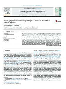
2.2 Digital Tomosynthesis imaging system Figure 2 shows the developed DT system to acquire the cross-sectional images of BGA. It consists of a scanning X-ray tube, an image intensifier, a rotating prism and a camera with zoom lens. The scanning X-ray tube is designed to control the position of an X-ray spot electrically and to project an X-ray beam into an object (PCB) at different directions. X-ray spot is steered on the PCB with a pre-defined circular trajectory. X-ray passing through the PCB is collected by an image intensifier. It has an important role as an X-ray detector. On its screen, photons of light are emitted in proportion to the X-ray intensity. At the eight or more pre-defined positions, a zoom camera via a rotating prism sequentially acquires images. The prism rotates to synchronize with X-ray position to catch the projected image on the screen of image intensifier as shown in Fig 2 (a). Captured images at 8 different positions are save in digital memory of PC and averaged to generate a cross-sectional image at focal plane. The x-ray imaging conditions in the system such as the projection angle and the magnification are determined by the geometric relations of the parameters, which are the radius of the rotating x-ray and the distances from X-ray to the object plane and to the surface of the image intensifier. The projection angle is an important parameter in the D T system, since the artifacts that cause distortions of the cross-section in the resulted image can be reduced or removed as the projection angle increases in general [l-41. In the developed X-ray imaging system, the incident angle for BGA solder joint inspection is set to 30 degree.
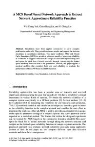
2.3 The cross-sectional image of BGA The schematic of Ball Grid Array joint and cross-sectional images at three differently located focal planes is shown in Fig 3. The focal plane is located at carrier, ball-center and pad. For the BGA inspection, the focal plane at carrier is selected. X-ray cross-sectional image of BGA solder joint by using laminography or DT method has inherent blurring effect and artifact as shown in Fig 3. This problem has been major obstacle to extract suitable features for classification. Neural network approach proposed here does not need efforts to extract suitable geometric features from solder joint images. Accordingly, the neural network method can be expected to be superior over the conventional geometrical feature based method.
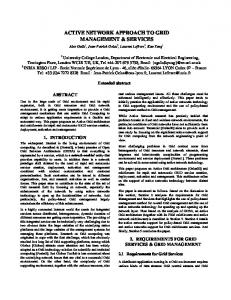
3. Neural networks for classification of defects in solder joints We proposed a neural network structure suitable for inspecting the X-ray cross-sectional images of BGA solder joints. The neural network has been used to tackle problems which can not be easily handled by the traditional analytic approaches. The approach has been successfully applied to the fields of pattern recognition and/or classification. The proposed neural network structure consists of four LVQ (Learning Vector Quantization) neural networks [4] and a multi-layered neural network [4] hierarchically. The 4 LVQ neural networks are used as a preprocessor to reduce the dimension of input images. They can cluster gray-level profiles acquired at 4 different directions (0, 45, 90 and 135 degree) as shown in Fig 4 and generate prototypes. They can convert gray-level profiles of input images into the Euclidean distances. Multi-layer neural network then learns only each Euclidean similarity distance between 4 directional gray-level profiles and their prototypes.
3.1 LVQ neural network for clustering of images Learning Vector Quantization neural network is one of well-known unsupervised neural network for clustering
234
and data compression. Clustering is grouping the similar patterns and separating dissimilar patterns without any priori information. In the proposed neural network scheme, LVQ cluster are used for the clustering of input graylevel profiles according to their similarities as a preprocessor of classic classifier. The network consists of an input layer and an output layer as shown in Fig 4. Each node in the input layer is connected directly to the neuron in the output layer. A weight vector called as prototype vector is associated with each neuron in the output layer. During learning procedure, the weights are updated so as to resemble each input data. In the self-clustering procedure, the output nodes compete with each other by similarity measures between an input image and the weights which are connected to the output neurons. Only one neuron, which has the weight closest to the current input data, is selected as a winner by the well-known competitive learning rule [6]. According to this rule, the weight of the winner output node only is qualified to be updated so that the weight approach one of members in its own cluster. The input of LVQ neural network is the gray-level profile of cross-sectional image of BGA. The number of neuron in input layer corresponds to the pixel number in line mask within predefined inspection window. The number of neuron in competitive layer is the same as the cluster number. It is difficult to find optimal number of output nodes. To find the number for various applications, various experiments with changing number of output neurons are executed. During recall procedure, a nearest neighbor classification technique is used.
3.2 Multi-layer perceptron neural network Multi-layer perceptron network is implemented to learn the mapping characteristics of human inspector and then to classify the solder joint quality from the cross-sectional image of BGA. The architecture for the network is shown schematically in Fig 4. The network consists of a large number of neuron arrayed in layers. The inputs of MLP network are the set of Euclidean distances in output nodes of 4-LVQ. The output data sets are the corresponding classification results of input data sets performed by human inspector. The neural network can learn the human classification rule during training procedure.
4. Experimental results and discussions 4.1 Sample images The sample images of the 220 BGA solder joints for experiments are collected from PCBs. These include various solder joint shapes according to the amount of solder. Among 220 samples, 160 samples selected randomly are used for network training, and the rest of 60 samples are used for testing. All samples are grouped by an expert inspector acceptable soldering (A), and excess into three classes according to their qualities: insufficient soldering (0, soldering ( E ) .Each sample image is 120 x 120 pixels in size.
4.2 Training of LVQ clustering network The input of LVQ clustering network is gray-level profile from BGA image in predefined window. The gray-level profile is collected in each 4 direction. Centroid of ball is calculated so that each profile center is located. The number of input node is set to 120 and the initial dynamic learning rate is set to 0.3 and decrease to 0.05 as learning epoch increases. The maximum learning epoch is chosen to 5000. The number of output node is selected to 7 by several experiments. Table 1. shows the clustering errors changing the number of output node of LVQ neural network. Each final weight vector is labeled corresponding to its soldering quality by a human inspector. These weight vectors are the representative of class and are called prototypes. LVQ clustering neural network can distinguish solder joint profiles according to the variation between their shapes and generated prototypes.
4.3 Training of MLP network The main feature of training the multi-layer neural network is to learn the relationship between inputs and outputs. The LVQ neural network is used for clustering of input gray-level profiles as pre-processor. The number of neuron in input layer of MLP is set to 4 times of the output neuron in one of LVQ because the neural network can use the clustering results of 4-directinal gray-level profiles as an input. The input data set of MLP neural network consists of the Euclidean distance of LVQ expressed by Eq. (1).
235
[d,’,d : ;..,d; ! d : , d i ;.., d,’ id,’, d:, ...,d: id,“,d,”,. . . , d ; ]
(1)
where d,b is the Euclidean distance between an input gray-level profile of uth direction and bth weigh vector, and expressed as follows.
dub
=I12
-@:I1
(2)
The corresponding output of give input data set is defined according to soldering quality by Eq. (3) [ 1,0,0] : insufficient soldering quality [ 0, 1,0] : acceptable soldering quality [ 0, 0, 1] : excess soldering quality
(3)
The number of neuron in hidden layer is selected experimentally. As a result, 28-20-10-3 structure is finally selected to classify the solder joint images.
4.4 Experimental results and discussions After training the two neural networks differently, classification performance of the proposed method was evaluated for the training images. Table 2 shows classification results for the training data. The results appear to be satisfactory because the training data of three quality Classes are accurately classified. From the test of learning performance of the proposed neural network, LVQ and multi-layered neural network are found with good accuracy to judge the solder quality of each ball on the BGA package. After the training, the classification performance was tested for remaining 60 ball images. These test data images were not used for the training. Table 3 shows the results of the test data. Only two samples in acceptable (A) class are mis-classified into the excess (I) class. The total success rate is therefore found to be 96.7 %, which is good for use in real industrial applications. In the solder joint inspection, insufficient solder is a crucial defect because insufficient solder joints can be cracked easily under vibrations or the shocks. For this reason, the success rate of the classification of the insufficient defects should be near 100% to design the classifier. From these experimental results, the success rate of classifying correctly the insufficient solder joints appears to be very high, which implies that the proposed classifier can be effectively used for actual application.
5. Conclusions A neural network approach is proposed to inspect BGA solder joints by using X-ray DT cross-sectional imaging system. To evaluate the classification performance of the proposed method, a series of experiments was conducted for various BGA solder joints of commercially manufactured PCBs. The experimental results show practical usefulness of the proposed method for solder joint inspection.
6. References [ 11 A. E. M. Bocage, “Laminographic imaging system for high energy radiation ”, French Patent 536464( 1922). [2] Adams, “X-ray laminography analysis of ultra fine pitch solder connections on ultra-thin boards”, Integrated Circuit Metrology, Inspection, and Process Control V (SPIE) Vo1.1464. 1991, pp 484-497. [3] Black, D. L. Millard, and K.Nilson, “An animated interface for x-ray laminographic inspection of fine-pitch interconnect”, IEMT Symposium 1991, pp 207-21 1. [41 M. Rooks, B. Benhabib, and K. C. Smith, “Development of an inspection process for ball-grid-array technology using scanned beam x-ray laminography”, IEEE trans. on Components, Packing, and Manufacturing Technology - Part A. Vol. 18, No 4, December 1995. pp 851-861. [5] Jacek M. Zurada, “Introduction to Artificial Neural Systems”, West Publishing company, 1992. [6] Y. Linde, et al., “An Algorithm for Vector Quantizer Design”, IEEE Trans. On Communication, Vol. com-28, no. 1, pp. 84-95, 1990. [7] Y.H. Pao, “Adaptive Pattern Recognition and Neural Networks”, Addison-Wesley, p p 269-330, 1989. [8] D. H. Ballard, “Computer Vision”, Prentice Hull, 1985.
236
B Avenged ln age
C
(a) Principle of laminograpy
(b) Corresponding images and result image
Fig 1. The principle of laminograpy
Scanning X-ray bbe
Zoom camera
(a) A schematic of the developed system
(b) The developed X-ray imaging system
Fig 2. Developed Digital Tomosynthesis system A : Ball center
B: Carrier C : Pad (a) A schematic of BGA
plane A
plane B (b) Cross-sectional images
plane C
Fig 3. A schematic of BGA solder joints and their cross-sectional images
237
Classificationresult
D
m
o.
ea
IO0
$0
plXd
Fig 4. Structure of the proposed neural network Table 1. Clustering errors of various output neuron Number of neuron
4
r error 34.3% 10.1% 0 QU77 . 0 /U
8.1%
Table 2 . Classification result for training samples
E
50 46
0
50 0
46
0
Q: quality, NS :no. of samples, NC : no. of confusion
Table 3. Classification result for test samples
E
21 22
0
19 0
22
Q: quality, NS :no. of samples, NC : no. of confusion
238
0