However, when the proac- tive information is inaccurate, it can lead the route setup message in a wrong direction. Therefore, if the first route setup attempt fails ...
A New Approach for Integrating Proactive and Reactive Routing in MANETs Frederick Ducatelle∗, Gianni A. Di Caro and Luca M. Gambardella Istituto Dalle Molle di Studi sull’Intelligenza Artificiale (IDSIA), Lugano, Switzerland {frederick, gianni, luca}@idsia.ch
Abstract We propose a new approach to integrate proactive and reactive routing in mobile ad hoc networks. Our work deploys a lightweight proactive algorithm that runs in the background offering a basic routing service, and a reactive algorithm that can be called on demand offering a connection-oriented service. The reactive algorithm uses the routing information from the proactive algorithm in its working, so that there is a synergy between the two parts of the system. An important property of our system is that it allows the choice between proactive and reactive routing to be made for each session individually, by their source nodes. This gives network nodes a very fine-grained level of control over the routing process, and allows them to exploit the complementary properties of proactive and reactive routing, e.g. by matching the choice of the routing approach to the needs of individual sessions. In a range of simulation tests, we evaluate the validity of our approach.
1. Introduction Routing algorithms for mobile ad hoc networks (MANETs) are typically classified as either proactive or reactive [13]. Proactive algorithms maintain routing information between all nodes in the network at all times. Examples are DSDV [11] and OLSR [4]. Reactive algorithms take a different approach: they only gather information for nodes between which data sessions are going on (in this paper we use the terms “session” and “flow” interchangeably). Examples include DSR [9] and DYMO [3]. Both approaches ∗ Corresponding author. This work was partially supported by the Swiss National Science Foundation through project 200021-108007 “Routing problems with objective functions of increasing complexity” and by the SWARMANOID project, funded by the Future and Emerging Technologies programme (IST-FET) of the European Commission under grant IST022888. The information provided is the sole responsibility of the authors and does not reflect the European Commission’s opinion. The European Commission is not responsible for any use that might be made of data appearing in this publication. The authors would like to thank Liliana Carrillo for useful input and fruitful discussions.
c 978-1-4244-2575-4/08/$20.00 2008 IEEE
have their advantages. Proactive algorithms usually deliver packets with lower end-to-end delay, as routing information is always available and updated, but might cause large amounts of overhead and incur high packet loss when they are not able to keep up with all changes in the network. Reactive algorithms, on the contrary, often cause less overhead and obtain higher packet delivery ratios, but can suffer from larger delays due to their on-demand nature. The complementary nature of proactive and reactive strategies makes it difficult to choose a single algorithm for all scenarios. Hence, standardization efforts in the MANET working group of the IETF [1] focus on two different algorithms: a proactive one (OLSR) and a reactive one (DYMO). This way, an individual choice can be made for each network deployment. Nevertheless, since the relative advantages of proactive and reactive routing are only understood in an approximative way, it is still difficult to make this choice even with a specific scenario in mind. Moreover, the situation might change during deployment, requiring to switch algorithms. One solution is to combine proactive and reactive routing in one system, as is done in hybrid and multi-mode routing (see Section 2). Also within the MANET working group, this possibility is kept open, “if significant commonality [between the proactive and reactive routing algorithms] is observed” [1]. We present a novel approach for combining proactive and reactive routing, called Integrated Routing Algorithm (IRA). It consists of a proactive algorithm that runs in the background and offers a best effort routing service, and a reactive algorithm that can be called on-demand and offers a connection-oriented service. A synergy between both algorithms exists because the reactive algorithm relies for its working as much as possible on the proactive routing information, e.g. during route maintenance and repair, so that the proactive system remains useful even when all data are routed reactively (this strategy was inspired by earlier work on the AntHocNet routing algorithm [6]). The most important property of IRA compared to existing work is that it allows nodes to choose between proactive and reactive routing for each data session individually, rather than expecting a single decision per node or for the whole network
together. This allows for a fine-grained and on-line tuning of the routing process. Such detailed adaptive control can be advantageous in a number of scenarios. For example, nodes can adapt their routing behavior to react to changes in the properties of the network, such as data traffic load or network mobility. Another appealing application is Quality-of-Service (QoS) provisioning, whereby nodes adapt their routing choices based on the requirements of individual sessions (e.g., a session requiring low delay can be routed proactively, while a session requiring low packet loss can be routed reactively). Here, we only describe the mechanisms applied in IRA for integrating proactive and reactive routing on a per-session basis, leaving the integration with QoS routing frameworks for future work. The rest of this article is organized as follows. First, we discuss related work. Then we present the IRA algorithm in detail, and after that we show results of simulation tests.
2. Related work The fact that proactive and reactive routing each have their advantages and that these are complementary has been recognized since some time [13]. There has therefore always been an interest in systems that let both approaches work together. Early work was focused on hybrid algorithms. These combine elements from proactive and reactive routing in a single algorithm. One example is ZRP [7], in which nodes maintain proactive routing information for destinations in their immediate neighborhood and use reactive routing for destinations further away. Another example is SHARP [12], which is based on the same ideas but is more adaptive. A related line of research is multi-mode algorithms, where nodes switch between proactive and reactive routing adaptively. In [14], the authors present an algorithm that uses proactive routing for a subset of all nodes, namely those that are reachable over stable links and those that are likely destinations of new sessions, and uses reactive routing for all other nodes. In [8] a system is proposed in which nodes individually decide whether to get involved in a proactive routing process or not, based on measured statistics about the network. Only data packets for which both the source and destination participate in the proactive process can use proactive routing. All other packets are routed reactively. Finally, in [10] the authors propose an approach in which all nodes run the same algorithm, which is chosen from a set of proactive and reactive algorithms. The article proposes mechanisms that let the nodes switch between routing algorithms simultaneously. Compared to our work, none of the approaches above offers the same fine-grained level of control for the decision between proactive and reactive routing: they allow decisions on a per-node basis or for the whole network together, while our approach supports decisions on a per-flow basis.
3. An Integrated Routing Algorithm In what follows, we first give a general overview of the IRA algorithm (Section 3.1). After that, we give details about the working of the proactive part (Section 3.2) and then about the reactive part (Section 3.3). We end with a short discussion about data forwarding (Section 3.4).
3.1. Overview of the system The working of IRA relies on a proactive algorithm that runs continuously in the background, and a reactive algorithm that can be activated when needed. Data packets are tagged to follow either proactive or reactive routes. The proactive algorithm periodically disseminates its routing information via locally broadcast update messages, which also serve as beacon messages. These messages are limited in size, and no extra messages are sent in response to disruptive events. As a consequence, the overhead created by each node is constant with respect to the rate of change of the network, the amount of data sent, and the size of the network. The downside of this design is that the performance of the algorithm can degrade, especially in very large or highly dynamic networks. The proactive algorithm can therefore only offer a best-effort routing service. The reactive algorithm offers a connection-oriented service, primarily focused on limiting data packet loss. It can be used whenever the best-effort service of the proactive routing information is not sufficient. The algorithm relies on a route setup to create an initial route at the start of a session. During the course of the session, it performs route improvement and route repair operations. The reactive algorithm makes extensive use of the information provided by the proactive algorithm. It does so during route setup, route improvement and route repair. The use of the proactive information makes the reactive algorithm more effective and efficient, as is shown in the evaluation in Section 4. This means that the proactive algorithm running in the background always gives a contribution to the system, even when all data is routed reactively.
3.2. The proactive algorithm Our proactive algorithm implements a multi-path version of Bellman-Ford routing [2]. Since it needs to function as a lightweight background process, it is designed to work efficiently under all circumstances. In what follows, we first describe the general working of the algorithm, and then give details about the routing information update process and the loop avoidance mechanism. 3.2.1. General working of the proactive algorithm The basic working of the algorithm is as follows:
1. Each node i in the network maintains a routing table Ti , with an entry tdij for each known destination d and each next hop j. tdij contains an estimate cdij of the cost of the route towards d over next hop j (estimations of link and route costs are based on the number of hops and the signal strength over the links, see [5]). 2. At periodic intervals (set to 1 s), node i broadcasts an update message containing for maximum m of the destinations in its routing table the best routing estimate cˆdi = minj∈Ni (cdij ) taken over all next hops j in its set of neighbors Ni (if it does not have a routing estimate to a previously known destination, it indicates a cost of infinity). m is a constant that limits the size of update messages (set to 20 in our tests). If there are less than m destinations, they are all are included in each message. Otherwise, update messages include subsets of m destinations selected in a round-robin fashion. 3. Each neighbor k of node i receives the update message, and uses it to calculate for each of the destinations d its own new estimate cdki for the cost of the route over next hop i to d. It does so by adding the estimate cˆdi received from i to the estimated cost of going from k to i. 3.2.2. The routing information update process The main difference between our proactive algorithm and other Bellman-Ford routing algorithms (such as e.g. DSDV [11]) lies in the way routing updates are spread. We only use periodic update messages that are limited in size. This means that routing overhead is not influenced by the occurrence of disruptive events, as no extra routing information is generated to deal with them (contrary to DSDV, where substantial changes are broadcast faster). It also means that routing overhead is not dependent on the network size: if the number of destinations exceeds m, information about them is spread over multiple subsequent update messages. In terms of implementation, routing update messages are piggy-backed on top of beacon messages. These are short messages that are broadcast periodically by all nodes to inform neighboring nodes about their presence. They are commonly used in MANETs to support link monitoring. Including the update messages inside beacon messages has as a main advantage that the total number of control packets is reduced. This is important because MANETs usually rely on contention based MAC layer algorithms, whereby channel access is costly. The downside of the proposed mechanism is that routing information is spread slowly over the network. While this does not mean that the algorithm does not converge to correct routing information, it does entail that this convergence can be slow, so that routing estimates can temporarily indicate erroneous routes. Data packets following erroneous
routes can encounter three possible scenarios. The first is that they are delivered over a sub-optimal path, the second is that they are dropped because they reach a dead end (a node that has no route for their destination), and the third is that they go in a loop. The first two scenarios lead to a degradation of performance: longer delivery times or packet loss. This is related to a design choice: we want to keep the proactive algorithm lightweight and efficient, and are prepared to accept that its performance degrades under certain conditions. The third scenario, of packets going in loops, is more problematic, as it can lay a heavy burden on the limited resources of the MANET. Therefore, we implemented a mechanism to avoid loop formation. 3.2.3. Loop avoidance The loop avoidance mechanism is based on sequence numbers, similar to DSDV. However, since DSDV is a single path algorithm while ours is multi-path, we use sequence numbers in a different way. The main idea is to have all destination nodes issue sequence numbers and spread these together with the routing information, and to let data packets only follow routes of increasing sequence numbers or decreasing costs. The general working is as follows: 1. Each node i maintains a local sequence number si . It also maintains in each routing table entry tdij a sequence number sdij , which is the last sequence number received for destination d over next hop j. Finally, it maintains for each destination d a sequence number sdi , which is the highest sequence number i has broadcast for d in its update messages, and a cost value cdi , which is the lowest cost broadcast for d related to this sequence number. 2. For each periodic routing update message, i increments the local sequence number si by 1 and includes it in the message. Then, it adds the best routing information for each destination d to the update message (as described earlier), and adds to this the sequence number sdij related to the best next hop j towards d. Finally, it updates sdi , its local record of the highest sequence number it has broadcast for destination d, and the associated lowest cost cdi as follows: if sdi < sdij , sdi is set to sdij and cdi is set to cdij ; otherwise, if sdi = sdij and cdi > cdij , cdi is set to cdij . 3. A node j receiving an update message from i stores the sequence number si in its routing table entry tiji as siji , the last sequence number received for destination i over next hop i. Then, for each destination d mentioned in the update message, it sets sdji to the received sequence number.
4. Data packets arriving in a node i for a destination d are only forwarded to a next hop j if sdij > sdi (the sequence number for d related to j in i is higher than the highest that i has broadcast for d), or if sdij = sdi and cdij ≤ cdi (the sequence number for j is the same as the highest i has broadcast and the cost for j is equal or lower than the lowest i has broadcast for this same sequence number). To understand how this mechanism ensures loop freedom, consider a packet following a path P = {1, . . . , h, i, j, . . . , n}. We indicate by sni and cni the highest sequence number and lowest cost broadcast for destination n by a node i along the packet’s path, and by snij and cnij the sequence number and cost stored in i for destination n over the outgoing link to j, which is followed by the data packet. From step 2 we know that snhi < sni , or snhi = sni and cnhi > cni (we use > rather than ≥ because the update of cnhi in node h involves adding the cost of going from h to i, which is greater than 0). From step 4 we know that sni < snij , or sni = snij and cni >= cnij . Now, suppose the hop from i to j closes a loop, i.e. node j is the same as a node f that comes before i. Then, we must have that snij ≤ snj , snj = snf , and snf ≤ snij . This is only possible if all of these sequence numbers are equal, but then we should have cnij > cnj , cnj = cnf , and cnf > cnij , which is impossible.
3.3. The reactive algorithm The reactive algorithm provides a connection-oriented routing service. At the start of a data session, it executes a route setup to build an initial route. During the course of the session, it applies route improvement mechanisms to adapt the current route to changes in the MANET. Finally, it has mechanisms to deal with link failures. The reactive algorithm makes as much as possible use of the information provided by the proactive algorithm, in order to get a synergy between both components of the IRA system. Below, we discuss each aspect of the reactive algorithm in detail.
The second way is by broadcasting. During the first attempt of a route setup, nodes use proactive information when it is available, and broadcast otherwise. Forwarding over the routes indicated by the proactive information can improve efficiency, as it limits the spreading of the route setup message compared to broadcasting. However, when the proactive information is inaccurate, it can lead the route setup message in a wrong direction. Therefore, if the first route setup attempt fails and a second and third are needed, only broadcasting is used for forwarding. Nodes receiving multiple copies of the same route setup message only process the first and discard all others. On its way from s to d, the route setup message collects a list P = [s, . . . , i, . . . , d] of all visited nodes. After reaching d, it returns to s retracing P . On its way back, it sets up reactive routing information in each of the nodes i ∈ P and in s. This information consists of a reactive next hop ndi for destination d and a reactive cost rid related to it. 3.3.2. Route improvement Route improvement takes place during the whole duration of a reactively routed data session. Its aim is to adapt the session’s route to changing conditions in the network. Each node s that is the source of a reactively routed session checks at regular intervals (set to 1 s) whether there is proactive routing information for the destination d of the session that is better than the currently available reactive route cost, i.e. minj∈Ni (cdij ) < rid . If this is the case, it is an indication that a better reactive route might be possible, and the route improvement process is started. s creates a route improvement message, which is routed towards d following proactive routing information: in each node i, the message is forwarded to next hop j = argminj∈Ni (cdij ). Route improvement messages are never broadcast; if they arrive in a node where no proactive routing information is available, they are discarded (to limit overhead). Once the message reaches d, it behaves like a route setup message: it traces its path back to s and updates in each node i the reactive next hop ndi and cost rid .
3.3.1. Route setup The route setup process constructs an end-to-end route between the source and destination of a session. It is used at the start of a new session, or whenever the source of an ongoing session falls without route. If a route setup process fails (i.e., no answer is received within a certain time), it is restarted. Each route setup gets maximally three attempts. To initiate a route setup, the source node s creates a route setup message. The aim of this message is to find a path towards a destination d. At any node i (including s), the message can be forwarded in two possible ways. The first is by using the proactive routing information related to d, i.e. the message is forwarded to next hop j = argminj∈Ni (cdij ).
3.3.3. Dealing with link failures When a node i detects the failure of a link (through link layer feedback or the failed reception of periodic beacon messages) to a neighboring node j, it removes any entries related to next hop j from its proactive and reactive routing information. Then, if the link failure lead to the failure of reactively maintained routes, it takes further actions, which depend on the specific situation. If i is the source of a failed reactive route, it starts a new route setup process. If, on the other hand, i is an intermediate node for a reactive route, it reacts with a route repair message if it currently has data to send to the destination of the failed route, and with a route
3.4. Data forwarding When a new data session is started, its source node decides whether it will be routed proactively or reactively. Every packet of the session is subsequently classified according to this decision, and all nodes in the network forward it along either proactive or reactive routes based on this classification. To mark a packet’s classification, we use the type of service (ToS) field of the IP header. We foresee two possibilities: either we use the precedence bits of the ToS field, or we use one of the unused bits at the end of the field. When we use the precedence bits, we mark proactively routed packets with bit pattern 000 (“routine” traffic according to the IP precedence classification) , and reactively routed packets with pattern 001 (“priority” traffic). The precedence bits of the ToS field also influence queueing and drop priorities, so that reactively routed packets get an improvement of their QoS experience compared to proactively routed packets. This is useful when we want to use IRA in combination with QoS provisioning. If this is not desired, we can instead make use of the last bit of the ToS field, which is unused and therefore has no consequences for queueing and dropping. We set this bit to 1 to indicate reactive routing, and to 0 to indicate proactive routing. In the tests of Section 4, we use the first method.
4. Experimental evaluation We carried out a number of experiments to evaluate the IRA algorithm. All of these are done in simulation, using QualNet 4.0. We deploy a MANET of 100 nodes in a rectangular, open area of 2400×800 m2 . The nodes move according to the random waypoint (RWP) mobility model [9]. We vary the maximum speed from 1 up to 20 m/s, to get scenarios of increasing difficulty. We use a minimum speed of 1 m/s (in order to avoid problems of decreasing average speeds in RWP [15]) and a pause time of 30 s. Each experiment lasts 1800 s, whereby during the first 900 s no
Fraction of delivered data packets
1
0.8
0.6
0.4
0.2
Reactive 100% Proactive 100% Reactive 50% Proactive 50%
0 0.07 Average end-to-end delay (s)
failure message otherwise. A route repair message is similar to a route setup message, as it follows proactive routing information whenever possible and is broadcast otherwise. The main differences between the two types of messages are that the maximum number of broadcasts for repair messages is limited (to 2), in order to reduce generated overhead, and that only one attempt is possible. A route failure message contains a list of all destinations that i lost a reactive route to, and is broadcast to all i’s neighbors. A neighbor j of i receiving the message checks whether it had a route over i to any of the mentioned destinations, and, if this is the case, removes this route and creates its own route failure message. If j is the source of any of the lost routes, it starts a new route setup process.
Reactive 100% Proactive 100% Reactive 50% Proactive 50%
0.06 0.05 0.04 0.03 0.02 0.01 0 1
5
10 15 Maximum node speed (m/s)
20
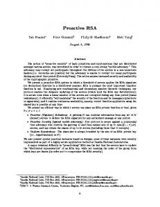
Figure 1. Delivery ratio and average delay for IRA under different routing scenarios.
communication takes place, so that the node distribution can get to a steady state. Each experiment is repeated 10 times with different node positions. Data traffic is generated by 20 constant bit rate sessions running between randomly chosen nodes. Sessions start between 900 and 1000 s after the beginning of the simulation, and run till the end. Each session generates 4 packets of 64 bytes per second. For the simulation of radio propagation, we use the two-ray signal propagation model. At the physical layer, we use the IEEE 802.11 protocol operating at 2 Mbit/s. The estimated radio range is 250 m. At the MAC layer, we use the IEEE 802.11 DCF protocol. At the transport layer, we use UDP. In what follows, we first investigate the performance in terms of delivery ratio and end-to-end delay of the proactive and reactive modes of operation of IRA, and how this relates to per-session service differentiation. Then, we compare IRA to existing reference routing algorithms. Next, we focus on the overhead, to evaluate efficiency. Finally, we investigate the synergy between proactive and reactive routing, i.e., in how far the reactive routing algorithm profits from the availability of proactive routing information. To evaluate the performance offered by IRA to proactively and reactively routed sessions, we study the packet delivery ratio and the average end-to-end delay in a number of scenarios. The results are shown in Figure 1. We distinguish between scenarios where all 20 sessions are sent reactively (“Reactive 100%” in the figure), scenarios where all session are sent proactively (“Proactive 100%”), and mixed
10 9
0.6
0.4 Reactive 100% Reactive/Proactive 50% Proactive 100% DYMO OLSR
0.2
0 0.16 Average end-to-end delay (s)
Overhead ratio in packets
0.8
0.12
Reactive 100% Reactive/Proactive 50% Proactive 100% DYMO OLSR
7 6 5 4 3 2
0 22
Reactive 100% Reactive/Proactive 50% Proactive 100% DYMO OLSR
0.14
8
1
20 18 Overhead ratio in bytes
Fraction of delivered data packets
1
0.1 0.08 0.06 0.04
16 14 12 10
Reactive 100% Reactive/Proactive 50% Proactive 100% DYMO OLSR
8 6 4
0.02
2
0
0 1
5
10 15 Maximum node speed (m/s)
20
1
5
10 15 Maximum node speed (m/s)
20
Figure 2. Delivery ratio and average delay for IRA, DYMO and OLSR.
Figure 3. Overhead ratio, in packets and bytes, for IRA, DYMO and OLSR.
scenarios where 10 sessions are sent reactively and the other 10 proactively (here, we show separate performance graphs for reactively routed sessions, “Reactive 50%”, and proactively routed sessions, “Proactive 50%”). It is clear that the algorithm’s ability to use either proactive or reactive routing for each individual session results in a differentiation of the service provided to the sessions: reactively routed sessions receive a higher delivery ratio (lower loss rate) than proactively routed sessions, but also a higher delay. The difference in delivery ratio remains stable as the network gets more dynamic, while the difference in delay grows. When we compare the performances between the mixed scenarios and the other ones, we can see that reactively routed sessions get better performance when less than 100% of the traffic is sent reactively, while proactively routed sessions get worse performance when less than 100% of the traffic is sent proactively. This is because the reactively sent data packets get priority in queueing and forwarding (see Section 3.4), and therefore an increase in the number of reactively routed data sessions increases the competition for resources in the network. To evaluate the competitiveness of our approach, we compare to DYMO and OLSR (version 2). Implementations of these algorithms are provided in QualNet 4.0. The results are shown in Figure 2. Here we use a single graph for the performance of the reactive and proactive sessions in the mixed test case (indicated by “Reactive/Proactive 50%”). In terms of delivery, IRA’s reactive algorithm outperforms
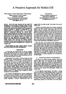
DYMO, while its proactive algorithm outperforms OLSR. In terms of delay, both DYMO and OLSR do worse than the different modes of operation of IRA. Moreover, the performance of DYMO degrades faster than that of IRA’s reactive algorithm. The interesting aspect here is that IRA in reactive mode gives better performance than the reference reactive algorithm, and IRA in proactive mode gives better performance than the reference proactive algorithm. Moreover, different from these algorithms, IRA also gives the possibility to switch between reactive and proactive routing. In these same scenarios, we also tested ZRP, a hybrid routing protocol, using the implementation provided in QualNet 4.0, but obtained very bad results for it. We also investigate the overhead ratio, both in terms of packets and bytes (calculated as the amount of control packets/bytes forwarded divided by the number of data packets/bytes generated). The results are given in Figure 3. The overhead created by the proactive algorithm can be observed by looking at the test case where all sessions are routed proactively. It is constant w.r.t. node mobility, which was a design objective of the system. The overhead created by the reactive algorithm can be observed in the case where all sessions are routed reactively, by subtracting the overhead created by the proactive algorithm. This overhead is relatively small, and increases slowly with node mobility. OLSR produces more overhead than our approach in all its different modes of operation. DYMO produces more overhead than IRA in terms of packets. In terms of bytes, the
tween proactive and reactive routing is made autonomously by the nodes, and can be different for each session. In a range of tests, we show that our algorithm gives good performance, that it can give different types of service to individual sessions according to the chosen routing approach, that it is efficient, and that the synergy between reactive and proactive routing pays off. Future work will focus on the inclusion of a monitoring module to give nodes feedback about the performance of proactive and reactive routing and support adaptive decisions, and on the integration with a framework for QoS provisioning.
Fraction of delivered data packets
1
0.8
0.6
0.4
Reactive with proactive support Reactive without proactive support
0.2
0 0.1
Reactive with proactive support Reactive without proactive support
Average end-to-end delay (s)
0.09 0.08
References
0.07 0.06 0.05 0.04 0.03 0.02 0.01 0 1
5
10 15 Maximum node speed (m/s)
20
Figure 4. Delivery ratio and average delay for reactively routed sessions with and without proactive routing information.
overhead produced by DYMO is lower, but it grows faster with node mobility. As pointed out in Section 3.2, limiting the overhead in number of packets is important in MANETs when a contention based MAC layer is used. Finally, we investigate to what extent the reactive algorithm profits from the availability of proactive routing information. We consider the case where all sessions are routed reactively, and compare the performance of the full IRA system with that of IRA without the proactive algorithm running in the background. In Figure 4, we show results for delivery ratio and end-to-end delay. For both measures, the reactive algorithm does much better when it has the support of proactive information. Also, it is interesting to see that the difference in performance grows for increasing levels of node mobility, even though the delivery ratio of the proactive algorithm shows a decrease in this case (see Figure 1).
5. Conclusions We have described a new approach to integrate proactive and reactive routing. The system consists of a proactive algorithm that runs in the background offering a besteffort routing service, and a reactive algorithm that offers a connection-oriented service. A synergy between the two is created since the reactive algorithm makes use of the proactive routing information whenever possible. The choice be-
[1] The internet engineering task force mobile ad-hoc networking page (MANET). http://www.ietf.org/html. charters/manet-charter.html. [2] R. Bellman. On a routing problem. Quarterly of Applied Mathematics, 16(1):87–90, 1958. [3] I. Chakeres and C. Perkins. Dynamic MANET On-demand Routing Protocol. IETF, February 2008. Internet Draft. [4] T. Clausen, P. Jacquet, A. Laouiti, P. Muhlethaler, A. Qayyum, and L. Viennot. Optimized link state routing protocol. In Proceedings of IEEE INMIC, 2001. [5] F. Ducatelle. Adaptive Routing in Ad Hoc Wireless Multihop Networks. PhD thesis, Universit`a della Svizzera Italiana (USI), Istituto Dalle Molle di Studi sull’Intelligenza Artificiale (IDSIA), 2007. [6] F. Ducatelle, G. A. Di Caro, and L. M. Gambardella. Using ant agents to combine reactive and proactive strategies for routing in mobile ad hoc networks. Int. J. of Computational Intelligence and Applications (IJCIA), 5(2), 2005. [7] Z. J. Haas. A new routing protocol for the reconfigurable wireless networks. In Proceedings of IEEE ICUPC, 1997. [8] J. Hoebeke, I. Moerman, B. Dhoedt, and P. Demeester. Adaptive multi-mode routing in mobile ad hoc networks. In Proceedings of PWC, 2004. [9] D. B. Johnson and D. A. Maltz. Mobile Computing, chapter Dynamic Source Routing in Ad Hoc Wireless Networks. Kluwer, 1996. [10] S. Nanda, Z. Jiang, and D. Kotz. A combined routing method for wireless ad hoc networks. Technical Report TR2007-588, Dartmouth College, 2007. [11] C. Perkins and P. Bhagwat. Highly dynamic destinationsequenced distance-vector routing (DSDV) for mobile computers. In Proceedings of ACM SIGCOMM, 1994. [12] V. Ramasubramanian, Z. J. Haas, and E. G. Sirer. Sharp: A hybrid adaptive routing protocol for mobile ad hoc networks. In Proceedings of MobiHoc, 2003. [13] E. M. Royer and C.-K. Toh. A review of current routing protocols for ad hoc mobile wireless networks. IEEE Personal Communications, 1999. [14] C. Santivanez and I. Stavrakakis. A framework for a multimode routing protocol for manet networks. In Proceedings of IEEE WCNC, 1999. [15] J. Yoon, M. Liu, and B. Noble. Random waypoint considered harmful. In Proceedings of IEEE INFOCOM, 2003.