A New Image Registration algorithm with application to 3D Histopathology Derek Magee1, Darren Treanor2, and Philip Quirke2 1 School
2 Pathology
of Computing, University of Leeds, Leeds, UK and Tumour Biology, Leeds Institute for Molecular Medicine, University of Leeds, Leeds, UK
Abstract— A method for automatic 2D image registration based on combining multiple row-wise and column-wise dynamic programming (DP) processes is presented. Combination is performed by means of a parametric transform (either rigid or non-rigid) which is estimated from the output of the dynamic programming processes. The method performs particularly well on histopathology images as dynamic programming is a global optimisation method with the ability to overcome local optima often encountered when registering such images. Our method has been applied to reconstruction of volumetric data from histopathology sections by serial application to successive pairs of images. An evaluation is presented that confirms our method compares favourably with state-of-the-art methods both in terms of accuracy and computational cost for this task. Microscopic 3D Histopathology has potential application in the analysis of anatomy and atlas building (e.g. in transgenic mice) and the analysis of tissue structure (e.g. in Liver disease).
I. I NTRODUCTION We present a method for automatic rigid, or non-rigid, image registration based on Dynamic Programming (DP). We have applied this method to volumetric reconstruction of histopathology data from serial sections. The advantage of our registration approach over popular gradient based methods (e.g. those in [1]) is that it is less susceptible to finding local optima. This is a particular problem when registering histopathology images, which contain a great deal of local structure at a range of scales (in comparison to radiology images which contain structure at a relatively small number of scales, and often contain large homogeneous areas). Chakravarty et al. [2] classify methods for reconstructing 3D volumes from serial sections into 3 types; i) Slice-to-slice methods; in which 2D sections are successively registered using a 2D:2D registration method (e.g. [3]), ii) Slice-toblockface methods; in which sections are registered to photographs of an uncut tissue block in a standard frame of reference (e.g. [4]), and iii) Global reference methods; in which 2D sections are registered to an existing 3D volume generated using MRI, CT, PET, or similar (e.g. [5]). While approaches ii) and iii) are desirable in terms of ensuring the volumetric validity of the reconstructed volume, they are limited by the spatial resolution of photography or volumetric scanning methods. Tissue samples in microscopic Histopathology are typically no greater than 1cm × 1cm (and are often smaller). Most commonly available volumetric MRI, CT or PET scanning methods do not have sufficient resolution for Corresponding author: Derek Magee, email:
[email protected]
such small samples (although new technologies are emerging). Photography could potentially be combined with some sort of modified microscopy to achieve the required resolution. However, the chemical stains used to identify tissue types in Histopathology are typically applied after sectioning, resulting in very different appearances pre- and post-sectioning. This, in addition to the difference in backlighting that would be present between digital microscopy and photographic image acquisition, would result in a challenging registration problem. For these reasons (and obvious time/cost advantages) we follow approach i). Creating volumetric data from sets of unaligned slices with no volumetric reference involves successively registering each slice to its predecessor (groupwise approaches are often inappropriate for histopathology data due to large changes in physical appearance/structure through the volume). As such, one failure results in the remainder of the volume becoming misaligned. A registration method with a very low failure rate is thus desirable. Empirically, gradient based optimisation methods (e.g. those in the Insight Toolkit [1]) do not always fulfil this criterion (figure 6). Our method was inspired by the fact that the (1D) direction and magnitude of misalignments in coronal and sagittal views of reconstructed volumes (which contain one row/column from each axial image) are often obvious when comparing one row to the next in these images. Optimal alignment of 1D datasets is a well studied problem solvable by methods including finding maxima of normalised cross-correlation, for a simple offset, or Dynamic Programming (DP), for a non-rigid transform. We choose DP, as histopathology data has small non-rigid deformations resulting from the physical cutting procedure. To ensure spatial coherence of the registration as a whole, we integrate information from multiple rows/columns by fitting a parametric function (e.g. rigid transform or B-spline). A. Background There are two broad categories of algorithms for automatically co-registering images1 ; voxel (e.g. intensity) based, and feature based. Voxel based methods have become dominant in the medical image analysis community for a number of reasons. Firstly, they are very applicable to medical images formed using the major modalities (X-ray, CT, MRI, PET) which have large homogeneous areas, but few sharp corners 1 By ‘co-registering’ we mean geometrically transforming a ‘moving’ image into a frame of reference defined by a ‘fixed’ reference image.
for feature detectors. Secondly, high quality freely available implementations exist (e.g. [1], [6]). Conversely, feature based methods are popular in the wider computer vision community for image alignment, image mosaicing and object matching [7], [8]. Typically, in these applications, images are taken from the real world using visible light cameras and contain a reasonable number of distinct features that may be successfully used for matching. Histopathology is a branch of laboratory medicine concerned with diagnosing disease by examining tissue with a microscope. Digital Histopathology images may be acquired using cameras mounted on microscopes, producing images of a few megapixels at a fixed magnification, or may be acquired by scanning tissue at high magnification to produce a gigapixel image with multiple levels of magnification (‘virtual slides’). We deal with the latter in this paper. Histopathology images (unlike radiology images) contain a great deal of local structure at a range of scales (resulting in large sets of features). However, this structure is often repeating, making it difficult to match features (especially if the initial offset between the images is large, which it often is). [9] use data specific algorithms to detect and match features in histopathology images (e.g. in data containing blood vessels a blood vessel segmentation algorithm is used). Features are matched using a Hough-like approach with pairs of features. Dynamic Programming (DP) [10] is a method which has long been used for dense matching of stereo image pairs [11], [12]. This (essentially) 1D problem is highly related to image registration. Pixels from one image are matched to pixels in another (i.e. the disparity calculated) assuming a 1D (horizontal) offset. DP may be used to optimally map two 1D signals based on a difference matrix between the two signals (D(n, m), where n ∈ all samples in signal 1, and m ∈ all samples in signal 2). The globally optimal mapping (that preserves signal ordering) is calculated by calculating an accumulated distance matrix from the distance matrix and ‘backtracking’ through this matrix. Signal noise and ambiguity can result in row-wise transforms that are not coherent (i.e. smooth) between neighbouring rows. A number of approaches, such as a second DP stage incorporating a smoothness constraint, have been proposed as a solution to this (see references in [12] as a starting point). Initial attempts [13], [9] at building volumetric data from sets of megapixel histopathology images include rigid and subsequent non-rigid stages. [13] suggest either using a data specific feature matching approach, similar to [9], or using voxel based methods from the Insight toolkit [1] on a scaleddown version of the image (after pre-alignment using a data specific Principal Components Analysis-based method) [14], with a subsequent non-rigid (block matching based) method. Later, we show that the ITK-voxel based approach is not always successful for histopathology data (it should be noted that we performed no pre-alignment and that we have had some success using this method on easier data sets). Reconstruction of a 3D volume from photographic sections for brain atlas generation was performed by Chakravarty et al. [2] using a previously presented registration method known as ANIMAL. However, this approach required manual segmentation of anatomical features which would not be practical if
high throughput was required. The closest approach to ours is that of Ju et al. [3] who use a Dynamic Programming method to successively register serial sections. Their method is similar to methods in the stereo image matching literature as it assumes the principal non-rigid transform is in a single (vertical) direction, as a result of the cutting procedure. The deformation in the horizontal direction is assumed to be a global offset of an integer number of columns. Smoothness between neighbouring columnwise calculated non-rigid deformations is ensured using a second pass of DP with an elastic smoothness term. This method assumes tissue samples are carefully placed on slides and scanned with the cutting direction aligned exactly with the vertical axis of the image (i.e. no rotation). In our experience manual preparation of glass slides can result in significant rotation and deformations perpendicular to the cutting plane (this is certainly the case for data sets used in this paper). It is desirable to have a generic registration method that works on a range of histopathology data. Such a method is presented in this paper. II. M ETHODS : VOLUMETRIC R ECONSTRUCTION BASED ON S UCCESSIVE REGISTRATION OF S ERIAL S ECTIONS Our method for reconstructing volumes from serial sections is based on the ‘slice-to-slice’ approach, as exemplified by [2]. A reference image2 , is selected (I0 ), and the neighbouring image (I1 ) registered to it using some (ideally automatic) image registration method. This process continues with each image being registered to the previous image (i.e I2 to I1 , I3 to I2 , etc.). We use three slight variations on this principle. Firstly, the reference image is selected to be in the middle of the set of sections (not at an end). The reason for this is that (in general) the middle sections contain the most tissue (e.g. a mouse embryo has little/no tissue at the limits of the sections), allowing the definition of the volume size before registration commences. This reference image is padded (as described later) by approximately 10% (defining the x and y volume dimensions). This allows for images that (when registered) may partially lie beyond the extent of the reference image (and would otherwise be truncated). Thus, two serial registration sequences are performed, one involving images preceding in order to the reference image, and one involving images subsequent in order to the reference image. This opens up the opportunity of parallelisation on conventional multi-core hardware. However, we have not implemented this. Secondly, the fixed image in our registration process (after the first registration) is the transformed image from the previous registration (rather than the untransformed image). This avoids the need to combine the set of transforms calculated (thus saving computational expense3). There is no reason (for our 2 in this paper we use ‘image’ to mean a 2D digital representation of a physical ‘slice’, or ‘section’. 3 An alternative way of saving computational time would be to parallelise registrations, with one 2D registration per processor. In this case we could not use this particular variation on the method. The serial limitation to such a parallelisation would be the combining of transforms, and warping of images. As such, the precise benefit of such a parallelisation would benefit from further investigation.
data) that this should detract from the registration performance, as image In is just as likely to be closer to the pose of I0 (i.e. the transformed pose of In−1 ) as it is to the original pose of In−1 . This is not the case in all serial registration applications (e.g. time sequences). The third variation on the method is to (optionally) use multiple fixed images (e.g. transform I2 based on both I1 and I0 ) in the registration process (described later as the DP-2 approach). The motivation behind this is to minimise accumulated error over the set of registrations. Within the ‘slice-to-slice’ approach any automatic 2D:2D image registration could be used. In the following section we present a novel method that performs particularly well on histopathology images (in comparison with standard methods). It is a simple extension to this method to use multiple fixed images. This extension is also presented. III. M ETHODS : 2D:2D R EGISTRATION U SING DYNAMIC P ROGRAMMING An overview of our 2D:2D registration approach is given in figure 1. This figure covers 2D registration of a ‘moving image’ to the frame of reference defined by a ‘fixed image’ (or images). Volumetric reconstruction from multiple sections (based on this method) is dealt with in the previous section. Update Transform and Iterate
Moving Image
Apply Transform
Transformed Moving Image Fixed Image(s)
D.P. Over Rows
dx
dy D.P. Over Columns
Least Squares Transform Estimation using (dx,dy)
Fig. 1. Overview of our Dynamic Programming Based Registration Method
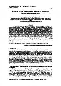
Registration works by performing dynamic programming (DP) separately on each pair of corresponding rows, and on each pair of corresponding columns (i.e. width+height separate DP applications per 2D registration). The moving image is padded (using the mean colour of all perimeter pixels) to be the same size as the fixed image. Thus, each pixel of row R in the fixed image is mapped to a pixel in row R of the moving image. A horizontal displacement (dx) is then calculated for each pixel in the fixed image as the distance between that pixel and its mapping in the moving image. The process is identical for column-wise alignment, resulting in a vertical displacement (dy) per pixel in the fixed image. The horizontal and vertical displacements are combined to give a 2D displacement field over the pixels of the fixed image (dx, dy). This 2D displacement field could be used to warp the moving image into the frame of reference of the fixed image (see figure 9 later). However, the field is likely to contain significant noise (especially if there is significant rotation). The (potentially noisy) dense transform field is regularised (de-noised) by fitting a parametric transform (rigid transform, or B-spline) in a least-squares error minimising way (see [15] for suitable methods). The process is repeated for a small number of iterations (typically 1, where G() is a spatial low pass filter). All pixels are included in the non-rigid transform estimation, as there is a risk of an under-constrained estimation problem otherwise. However, the penalty term in the DP process ensures reasonably accurate fields after calculation of the rigid transform, even in homogeneous areas (as the solution is close). Application of our approach to synthetic data (see later) identified a potential issue relating to (approximate) rotational symmetry in the data. If there is rotational symmetry the different DP processes can give conflicting information (figure 2). However, the penalty term penalises against large displacements, and the effect is irrelevant if displacement is aligned with one of the axes, so this is not a common problem.
Fig. 2. Problem resulting from Rotational Symmetry when registering the solid ellipse to the outline ellipse
In figure 2 the dx field suggests a clockwise rotation, whereas the dy field suggests an anti-clockwise rotation. Estimating a transform from such a field gives a result with a much smaller displacement than suggested by the field. Our solution is to explicitly pose registration as an optimisation problem (as in gradient based methods). If we choose a comparison metric to optimise (we choose sum of squared differences between
RGB values, although Mutual Information, or other measures, could be used) we can determine if the calculated transform increases the optimality of the metric. If the transform estimated from the complete field decreases the optimality, we have the option of calculating a new transform based on either the dx or dy part of the field alone (or reverting to the previous estimate). Figure 3 illustrates the process. The sum of the accumulated differences over all row-based, and all columnbased, DP processes respectively is calculated and used to decide which single directional field to use first ((dx, 0) or (0, dy)), based on the minimum of these two values. Calculate transform from (dx,dy)
No
Yes
Use
Metric reduced?
transform * fromCalculate either (0,dy) or (dx,0)
No trans. * Rigid only transform * fromCalculate either (dx,0) or (0,dy)
Fig. 3.
Metric reduced?
Yes
Use
No
Yes
Use
Metric reduced?
Use transform from (dx,dy) anyway, but store previous transform as ‘best’
Posing registration as a metric optimisation problem
Posing registration as metric optimisation allows automatic analysis of the convergence of the process. Thus, we can define a stopping criterion. The criterion used is that the metric has not increased in optimality beyond the ‘best’ in Nstop iterations (typically 5). This is superior to a criterion where the process is stopped immediately the metric has not been increased in optimality at that iteration as our method has the ability to overcome local optima (not being gradient based). Including multiple possible transform estimates introduces no overhead (except metric calculation) under most circumstances as the extra transforms are not estimated. Calculation of the metric is useful in defining a stopping criterion whatever the method. C. Interactive Multi-level registration We have implemented an interactive multi-level registration approach for dealing with Gigapixel histopathology images. In common with other iterative registration methods in the literature, it is not practical (for computational reasons) to apply our method on full resolution digital histopathology slides (full size data sets are ≈ 120K × 80K pixels per image). Running our (unoptimised) implementation of our method on images of size 125×125 results in registration within around 35 seconds per slice (Pentium IV 3GHz). Complexity is O(N 2 ) with image width N . In comparison, gradient based methods from the Insight Toolkit [1] took (in ad-hoc tests, using 4 levels, max. iterations=1000) between approximately the same time and twice as long on the same data. Qualitatively our method works well when applied to histopathology images of such resolutions (no large discontinuities are observed in coronal/sagittal views of the reconstructed volumes). This is an acceptable time-frame for clinicians. However, such images have widths/heights around 512 times smaller than the current maximum resolution of slide scanners. Thus, small errors in calculated low resolution transforms are scaled up to become large errors at the native resolution. Our solution is to implement an interface where the user can interactively
select sub-areas of the image to register at higher resolution, using the lower resolution output as an initial solution. This is illustrated in figure 4.
was applied to the generated volume in 3 directions (x, y and z) to introduce (potential) extra local optima in the registration process. Each slice was then transformed by a random angle and translation (rotation range [-45:45] degrees, translation range [-50:50] pixels). V. M ETHODS : E VALUATION M ETHODOLOGY
Fig. 4. Performing Registration at Successive Image Magnifications using interactive sub-image selection
IV. M ETHODS : DATA P REPARATION Data used within this paper falls into two categories i) Virtual slides of human and animal tissue (ground truth not known), and ii) synthetic data approximating the real tissue (ground truth known). This data is illustrated in figure 5.
Aligned volumes were generated based on ≈ 1000 × 1000 pixel images (magnification 1/64 full resolution for real ‘virtual slide’ images). This size was chosen for convenience, as such volumes fit comfortably in the memory of a fairly standard PC. Both the method detailed in this paper, and various versions of rigid registration code from the Insight Toolkit [1] were evaluated with different settings. For all data sets qualitative performance was judged by viewing the reconstructed volumes in Coronal and Sagittal views. These views contain one row from each image in the set. As such, misalignment errors can be seen fairly clearly as discontinuities between rows. For the synthetic data (where ground truth is known) a pixelby-pixel evaluation of the magnitude of the mis-alignment was performed. The mean and maximum error with respect to the ground truth was calculated. VI. R ESULTS
i)
iv) Fig. 5.
ii)
iii)
v) Examples of original images from each data set (“axial views”)
Data sets prepared were; i) 48 Slices from a human liver with Cirrhosis (stained with sirius red), ii) 70 slices from a human liver containing a deposit of metastatic carcinoma adjacent to a blood vessel (stained with H&E), iii) 112 slices of a mouse embryo (stained with H&E), iv) 100 slices of a synthetic liver dataset (loosely based on i)), and v) 100 slices of a synthetic mouse embryo dataset (loosely based on iii)). Tissue sections were prepared using standard histological techniques as follows: Tissue was formalin fixed, processed and paraffin embedded. 3-5 micron serial sections of the paraffin blocks were cut and selected sections (eg. every 10th section for the liver; every single section for the mouse) were stained using either haematoxylin and eosin (H&E) or sirius red depending on the application. The glass slides were scanned using Aperio T2 and T3 scanners using 20x and 40x objectives, producing images with a final resolution of 0.23 to 0.46 microns per pixel. The synthetic data was generated by hand defining a set of ellipses and cuboids in volumetric space (with corresponding colours), so as closely as possible to simulate real data sets. A sinusoidal attenuation ([rgb]new = [rgb] × (1 + 0.1sin(0.5x)))
A. Qualitative and Quantitative Evaluation of Registration Accuracy Coronal views through the centres of reconstructed volumes are shown in figure 6. For data set i no method ‘failed’ (exhibited a gross error resulting from termination of the method due to local optima) on any pair of slices. However, minor errors are observed to accumulate over slices (in particular for the ITK-SSD method). Our method based on the two previous slices is the best in this respect (although the effect can be reduced by registration at greater image magnification for all methods). For data set ii neither version of our DP method exhibits ‘failures’, although the 2 slice version has reconstructed the blood vessel (vertical white structure) as a smoother structure (which is more consistent of how we would expect blood vessels to be). At least Two ‘failure’ registrations can be seen for the ITK-MI method (note discontinuity in blood vessel). While no major failures can be seen for the ITK-SSD method, the blood vessel appears slightly distorted, and there is minor misalignment towards the bottom. Data set iii shows a clear distinction between our approach and ITK based approaches. While our method is successful, the ITK methods exhibit numerous errors evidenced by discontinuous lines, and false texture in the images (we encourage readers to examine the electronic version of this paper at high magnification). For the synthetic data sets our method (DP/DP-2) exhibits no failures, whereas the ITK methods exhibit multiple failures. For the synthetic data sets the ground truth is known, and the relative performance of various versions of the different algorithms may be compared. Tables I and II summarise the distribution of the absolute error between the ground truth and the estimated transform over all foreground voxels (N.B.
i)
ii)
iii)
DP
DP-2
ITK-SSD
ITK-MI
DP
DP-2
ITK-SSD
ITK-MI
DP
DP-2
iv)
v)
DP
DP-2
ITK-SSD
ITK-MI
DP
DP-2
ITK-SSD
ITK-MI
Fig. 7. Coronal views through the centre of (rigidly) reconstructed volumes of synthetic data for various methods (inferior approaches not shown for brevity)
calculated parametric transform. The latter approach is more computationally efficient, and we will take this approach in future work. ITK-SSD
ITK-MI
Method Levels Max. image scale Mean Error Max Error DP 1 125x125 2.48 7.31 DP-2 1 125x125 1.87 6.84 DP 2 250x250 2.20 5.68 DP-2 2 250x250 1.91 5.13 ITK-SSD 1 125x125 9.77 42.89 ITK-MI 1 125x125 9.46 44.87 ITK-SSD 4 250x250 9.75 44.85 ITK-MI 1 250x250 9.41 37.05 TABLE I P ER - VOXEL ERRORS STATS OVER VOLUME FOR VARIOUS METHODS/ IMAGE
Fig. 6. a) Coronal views through the centre of (rigidly) reconstructed volumes of real data for various methods (DP: Our method with single fixed image, DP-2: Our method with 2 fixed images, ITK-SSD: ITK Multi-scale local rigid registration based on Sum of squared differences, ITK-MI ITK Multiscale local rigid registration based on Mutual Information. Registration was performed using 1/8 scale images, with 1 image level for DP methods, and 4 image levels for ITK based methods (although 1 and 2 levels gave qualitatively similar results)).
This is the accumulated error, not the slice-to slice error, which is much smaller). From this it should be clear that our method outperforms the ITK methods, and using 2 fixed images is superior. A deterministic error can be seen in the DP (and to a lesser extent DP-2) registrations for the synthetic data. This is the result of our (zero-order) interpolation of the transformation field in the multi-scale registration process when going from one level to the next. A better approach would be to use linear (first order) interpolation, or scale the
SCALES USING SYNTHETIC LIVER DATA ( ERRORS ARE PERCENTAGE OF RECONSTRUCTED VOLUME WIDTH ;
1000 PIXELS ). O NLY RESULTS
CORRESPONDING TO THE NO . OF IMAGE LEVELS WITH THE MINIMUM MEAN ERROR ARE GIVEN FOR
ITK BASED ALGORITHMS FOR BREVITY
(1,2 AND 4 WERE TRIED FOR EACH METHOD/ DATA SET ).
B. Multi-level reconstruction Results A reconstructed full resolution image of a rat kidney glomerulus (actual size ≈ 100µm) is shown in figure 8a. An axial view of the same glomerulus is shown in figure 8b for comparison (glomeruli exhibit no directionality, thus these should be comparable). In this example the inter-slice distance is approaching the in slice image resolution (0.5 µm vs. 0.12 µm) and individual cell nuclei may be distinguished.
Method Levels Max. image scale Mean Error Max Error DP 1 125x125 2.22 9.83 DP-2 1 125x125 1.78 6.76 DP 2 250x250 2.00 16.78 DP-2 2 250x250 1.61 4.54 ITK-SSD 1 125x125 7.09 31.34 ITK-MI 1 125x125 8.35 37.13 ITK-SSD 4 250x250 6.45 31.17 ITK-MI 1 250x250 7.53 35.00 TABLE II P ER - VOXEL ERRORS STATS OVER VOLUME FOR VARIOUS METHODS/ IMAGE
i)
ii)
iii)
iv)
v)
vi)
SCALES USING SYNTHETIC MOUSE DATA ( ERRORS ARE PERCENTAGE OF RECONSTRUCTED VOLUME WIDTH ;
1000 PIXELS ). O NLY RESULTS
CORRESPONDING TO THE NO . OF IMAGE LEVELS WITH THE MINIMUM MEAN ERROR ARE GIVEN FOR
ITK BASED ALGORITHMS FOR BREVITY
(1,2 AND 4 WERE TRIED FOR EACH
METHOD/ DATA SET ).
a)
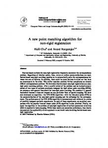
Fig. 9. i) Fixed Image, ii) Moving image, and Image transformed with unregularised field (dx,dy) calculated with; iii) P=0, iv) P=250, v) P=500, vi) P=1000
b) Fig. 8. a) Coronal view of reconstructed rat kidney glomerulus using three iterations of B-spline+rigid transform estimation subsequent to convergence of the DP method using rigid transform only (Non-rigid registration performed only at the highest magnification level), b) Axial (original) view of the same glomerulus
(allowing a more accurate estimate at the next iteration). The optimal value of P (by inspection of these images) is around 200-250 for the dis-similarity functions described in the paper. There is no theoretical basis for this being dependent of image size, and empirically this appears to hold true. VII. D ISCUSSION
C. Selection of non-diagonal penalty term The non-diagonal penalty term in the DP process (see section III) is is key to the success of the algorithm, ensuring a locally rigid transform if image data is insufficiently textured (or has too low signal to noise ratio) to give a reliable estimate of the transform. A value of P = 200 is selected based on manual inspection of images transformed by DP generated fields. Figure 9 illustrates the effect of varying this term (P ) for the initial offset of two images with approximately 30 degrees rotation. From figure 9 it can bee seen that Increasing P reduces noise in the transform field. However, excessively high values (e.g. 1000) simply result in a near-identity transform. Transformed images based on raw (unregularised) fields (dx,dy) from iteration 1 are shown (noise is reduced in later iterations, so this represents worst case noise). It should noted that the DP method produces imperfect fields without regularisation by a parametric transform in the initial iterations. The field tends to be a mix of near-correct results, and near-identity transforms for significantly non-zero P (whereas there is significant random noise for lower values of P). As such, the least-squares transform moves the moving image closer to the fixed image
AND
F UTURE W ORK
We have presented a Dynamic Programming (DP) based approach for 2D image registration that is less susceptible to local optima than metric gradient optimisation methods currently popular in the medical imaging community. The reason for this is that DP is (in some sense) a global optimisation method. This lower susceptibility to becoming stuck in local optima increases the range of initial offsets possible. This makes it particularly suitable to the registration of histopathology images. This method is at least as computationally efficient as gradient-based methods (if not significantly more efficient in some cases). The principal reason for this computational efficiency is that very few iterations of the process are required (typically