lpH; magnetizing inductance: 48pH. Cl, C2 - 6811F, polypropilene. C3, C4 - 1Ot0O0pF/25V, electrolitic. C5. - 3,0OOpF/25V, high frequency electrolitic capacitor.
A NEW ISOLATED HALF-BRIDGE SOm-SWITCHING PULSE-WXDTH MODULATED DC-DC CONVERTER Amaldo Jose Perin, Member IEEE; Ivo Barbi, Senior Member IEEE Federal University of Santa Catarina Dept. of Electical Engineering, Power Electronics Laboratory Caixa Postal 5119,88049 - Florianopolis - SC - BRAZIL Phone: 55.482.31.9204 Fax: 55.482.34.1524
ABSTRACT - This paper presents a new isolated halfbridge soft-switching dc-dc converter, regulated by pulse-width modulation. To achieve regulation of the power transferred to the load a t constant frequency, an auxiliary switch commutating a t zero current is placed between the output rectifier and the load, wich is synchronously gated with the main switches. Principle of operation, theoretical analysis, design procedure and example, along with laboratory experimental results, are provided.
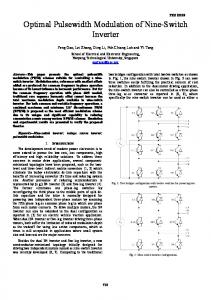
1 .INTRODUCTION The circuit shown in Fig.1 has the following properties:
Fig.1
The transistors commutate a t zero voltage;
- FM-ZVSDC-DCConverter
Both circuits are shown in Fig. 2.
All the parasitic parameters, such as leakage inductances and power semiconductors intrinsic capacitances, are totally absorbed, taking part into the commutation process. However, it is regulated by frequency modulation, undesirable feature that engineers have been trying to eliminate. Operation at constant frequency has been achieved with the employement of the techniques as follows: a) Variable Lr inductor, proposed in reference 111. However, it needs an additional inductor, of considerable weight and size, precluding the use of the leakage inductance as resonant inductor. b) Replacing the output diode, reference [2] , with transistors. The output voltage is regulated by phase shift and the conduction losses are reduced. Furthermore, the converter becomes reversible. This technique is suitable for high power applications.
Fig2
variable
resonant inductor and b) phase shift.
This paper proposes a different method to perform regulation of the presented converter at constant frequency, wich consists on the employement of an additional transistor placed after the output rectifier.
66 0-7803-0485-3l92 $3.00 0 1992 IEEE
(b) - Constant frequency ZVS DC-DCconverters. a)
2. THE PROPOSED CIRCUIT AND PRINCIPLE O F
-4th. stage (t2,t.j) - Fig. 4d: at moment t p , D2 starts conducting i L M plus i L r . During this time interval Q2 is gated on at zerovoltage and zero-current. Current iLM and iL,- decrese in a linear way. At the instant t 3 , iL~ reaches zero and Q3is turned off at
OPERATION
The proposed circuit and i t s equivalent circuit with the output stage transferred to the transformer primary side, is represented in Fig. 3. Q1, D1, C1, 02, DE, and C2 form a ZVS Commutation Cell. The transformer magnetizing inductance LM ensures proper commutation at noload. The power transferred to the load is controlled by Q3, wich turns on and off at zero current, and is synchronized to the switches Q1 and Q2.
zero-current and zero-voltage. -5th. stage ( t 3 , t 4 ) - Fig. 4e: during this time interval i L r is equal to zero and the magnetizing current iLM keep flowing through LM and D2. At the instant t 4 the half-cycle of operation is terminated. I t is noted that Q 1 and Q2 arc gated complementary and do not regulate the power transferred to the load. They just produce an AC voltage on the transformer windings.
One important property of this circuit is its ability t o commutate Q 1 and Q2 at zero-voltage even a t no-load, due t o the magnetizing current that is not dependent on the output voltage, as in the phaseshifted ZVS converters. The correspondig relevant waveforms are depicted in Fig. 5.
theoretical
The output voltage is regulated by the dutycycle defined as D = 2 - A T i / T . The large is the time interval AT1 the large is the power transferred to the load. Fig.3. - a) The proposed converter and b) the corresponding equivalent circuit.
3. THEORETICAL ANALYSIS The operation of the proposed converter is described as follows: a l s t . stage (tO,t01)
-
Fig. 4a: at moment t o , the magnetizing current flows from (b) t o (a), through LM, D 1 and V,/2. 0 1 is at on state. 03 is gated on and starts conducting the current i L r , which raises linearly. Q3 turns on at zero-current.
3.1 Output Characteristics
In order to facilitate the obtention of the output characteristics, the following assumptions are made: The transformer magnetizing inductance is very large.
-2nd. stage ( t o l , t 2 ) - Fig. 4b: a t moment t 0 1 , i LM reaches zero and becomes positive, flowing from (a) to (b). Currents i L M and iL r continue increasing linearly through Q1. .3rd. stage ( t l , t 2 ) - Fig. 4c: at the instant Q 1 is turned off a t zero current. The currents i L M and i L r are deviated from 0 1 to C 1 and C2. C 1 discharges and C2 charges linearly. During this time interval iLM and iL r are assumed constant. This commutation ends at the instant t 2 , when Vc1 reaches V, and Vc2 reaches zero.
The commutation is instantaneous. All the semiconductors are ideal. All Conduction losses are negligible. The transformer turns ratio is equal t o one.
t i transistor
During the time interval AT1 = t i current 5 L r is given by:
67
1
to,
the
ILm
c
1
I
1
1
Fig. 5
- Relevant theoretical waveforms
Thus:
Let us define: Fig. 4
- Stages of operation of a half-cycle of the proposed converter.
q
=
-"0
(3)
VS
Expression (12) represents the converter output characteristics, wich are shown in Fig. 6.
qt
(4)
The substitution of (3)and (4) in expression (2) gives: DOVS ( 1
I =
- 2q 1
(5)
4.Lr.f
During the time interval AT3 = t 3 - t 2 , assuming that AT2 = t 2 - t i = 0, I L r is given by:
Lr
Fig. 6
- Theoretical
output characteristics
When: t = AT3, 1 L r = 0. Thus: The maximum duty-cycle takes place when AT3 =
AT4 = t 4 - t 3 equals zero. This implies that:
2.Lr.I
(7)
1 + 2q 1
Vs'(
AT1 + A T 3 = T I 2
As a consequence:
Using expressions (41, (8) and (131, the maximum duty-cycle is obtained, which is given by expression (14).
2.Lr.I.f
2-AT3 -
(8)
5
T
1 + 2q 1
V,*(
1 + 2q
Dmax =
Therefore with expressions (5) and ( 8 ) we obtain: 2.AT3
Do( 1
-=
T
-
(9)
T
2eAT3 T
(14)
During the commutation of Q 1 and Q2, I is assumed constant.
The output average current is representated by expression (10). 2-ATl
2
3.2 Commutation Analysis
2q 1
( 1 + 2 q )
Io=I(-+-
(13)
1
I 1 = ILM + I
(15)
where:
(10)
By substituting expressions (4) and (8) into (10) and defining:
ILM =
VS
8.Lpl.f
(16)
thus: (11) AT2 =
we get:
2*c.vs
11
where: D2
-
4-10
-
8.1
(12)
cl= 2*D2
AT2 = t 2
69
-
t1
(17)
c
=
c1
=
(18)
c2
5.
Calculate
the
equivalent
resonant
inductor
At no-load, I = 0 and
Vs*(l Lr =
(19)
-
D4minI2*(1
-
4q2)
16-f.1,
6. Calculate the commutation capacitor
(20)
1 - 4q2 1
V,.(
Imax = so
where: WO (21)
=
2.1r.f~
7. Calculate the relevant time intervals
8.Lr.f
9
In order to ensure the commutation from no-load t o full-load, the dead-time between 0 1 and Q2 must be larger than AT2max.
L r ' Imax AT3max = vs12 + v,
4. DESIGN PROCEDURE AND EXAMPLE A design example is given as follows:
The design procedure of the proposed converter is described as follows:
1. Input data:
1. Input data:
- Vs (input voltage) V o (output voltage)
f = 100KHZ; f o = 40OKHZ
Po (output power)
f (switching frequency) f
2. I o
=
3. Let
US
PolVo = 225120 = 11.25W
take ATqmi n
=
0.5pS. Thus:
(resonant frequency)
2. Output Current: I, = P,IV, 3. Calculate
4. Calculate the maximum peak current
with: q
= VolVs
=
20180 = 0.25
70
I -
'
where:
wo = 2 * n . f o
A comercial capacitor of 68qF has been selected.
ATlmax =
AT3max
L r Imax
-
v,/2
v,
L r * Imax
vs/2 +
v,
=
3.375ps
= 1 . 1 2 5 ~ ~
In the design procedure and example, a unity transformer turns ratio was adopted. A 250W/100KHz transformer was designed fabricated. Its measured inductance were: LM = 49pH and 1s + lp= 1 . l p H (leakage inductances). Thus, the external resonant inductor is given by: l r = Lr - 1 s l p = 1.6pH. and
-
5. EXPERIMENTAL RESULTS
In order to verify experimentally the principle of operation of the proposed converter, and the validity of the theoretical analysis, a laboratory prototype has been implemented, whose power stage diagram is shown in Fig. 7. It consists of the following components:
1 vs
L
V
Fig. 7
I
- Power stage diagram of the implemented
- IRFS~O D l , D2 - MOSFET body diodes D3, D4, D5, D6 - MUR815
I
prototype.
a1, a2
Fig. 8 -Experimental waveforms. a) The turn-off time interval of 01. b) The turn-off and turn-on period of the auxiliary transistor Q3. c) Current on the primary side of the transformer and voltage vab. d) Current on the secondary side of the transformer and output voltage.
71
0 3 - 2 x IRF540
There is no overvoltage stress across the transistor.
- 1.5~H Tr - Core E 4 2 / 1 5 1,
in contrast to the ZVS converters regulated by phase shift, the magnetizing inductance takes part in the commutation process, ensuring zero-voltage switching from no-load to full load.
(Thornton); primary: 16 turns; secondary: 16 turns; primary plus secondary leakage inductance: 1.lpH; magnetizing inductance: 48pH. C l , C2
- 6811F,polypropilene
because all parasitic components are absorbed, i t is suitable for high frequency, high power applications.
C3, C4 - 1Ot0O0pF/25V, electrolitic
C5 - 3,0OOpF/25V, electrolitic capacitor.
high
frequency
The specifications are as follows: V, = 80V (input voltage)
f = lOOKHz (switching frequency)
Po = 225U (output power)
Yo = 2OV (output voltage)
REFERENCES [ 11 A. S . Kilowski, ' Half-Bridge Power-Processing Cell Utilizing a Linear Variable Inductor and Thyristor-Dual Switches', IEEE-PESC 1988, Conf. Record, pp. 284 - 289.
(21 M. H. Kheraluwala, R. W. Gascoigne, D. M. Divan and E. Bauman, 'Performance Characterization of High Power Dual Active Bridge DC/DC Converter', IEEE-IAS 1990 Annual Meeting, pp. 1267 - 1273.
The relevant experimentally obtained waveforms are depicted in Fig. 8. They demonstrate that 01 and 02 commutate at zero voltage, while Q3 commutates at zero current. The measured efficiency was 80.4%. The conduction losses, which are the main responsible for the overall losses, can be significantly reduced by the employement of a midle-point output rectifier in the place of the full bridge one. In off-line applications, with a high input voltage, the RMS current through the MOSFETs will be reduced and the overall efficiency will increase even more.
CONCLUSION This paper presented a novel concept to regulate a soft-switching half-bridge isolated dc-dc at constant frequency. converter operating Theoretical analysis, design procedure and example, and experimental results were provided. From the performed studies, the following conclusions can be drawn: all switches commutate at practically no switching losses. the output voltage is regulated by PWM in a manner similar t o the conventional converters.
72