Cite this paper as: Wang M., Ding H., Wang G. (2013) A Novel Method Using Camera Calibration Technique for Complete Geometric Calibration of Cone-beam ...
A Novel Method Using Camera Calibration Technique for Complete Geometric Calibration of Cone-beam CT Mengjiao Wang, Hui Ding, Guangzhi Wang Department of Biomedical Engineering, School of Medicine, Tsinghua University, Beijing, China Abstract—Cone-beam computed tomography (CBCT) is deployed in large numbers for small animal imaging. For accurate reconstruction, geometric parameters of CBCT must be known. In this paper, a novel method using camera calibration technique for CBCT geometric calibration is proposed. Geometric relationships of X-ray source, detector and rotation axis are obtained to calculate CBCT geometric parameters. Simulation results show that accuracy of this method is improved compared with previous methods. Keywords—cone-beam computed tomography, geometric calibration, camera calibration technique
I. INTRODUCTION
Cone beam computed tomography (CBCT) is deployed in large numbers for small animal imaging. For accurate reconstruction, geometric parameters of CBCT must be known. However, the nonidealities of CBCT geometry, which can cause severe image artifacts, are inevitably due to errors of mechanical assembly. This makes geometric calibration a significant issue for CBCT research. In the last decades, many efforts have been made in CBCT geometric calibration. The previous methods can be divided into two major groups: iterative methods and analytical methods. These methods used indirect geometric relationship to calibrate CBCT system. The assumption that some parameters are ideal or neglectable is always applied. And complexity of these methods increases by applying iterative method or indirect geometric relationship [1-3, 5]. In this paper, a novel CBCT geometric calibration method using camera calibration technique in computer vision is presented. CBCT system is considered as a pin-hole camera model here, and the process of acquiring projections can be considered as camera photographing object in different views. Camera calibration technique is applied to get direct geometric relationship of X-ray source, detector and rotation axis. Furthermore, CBCT geometric parameters can be derived. The accuracy of this method is increased, while the complexity is reduced.
II.
METHOD
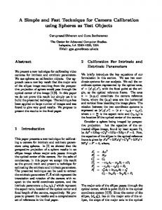
CBCT system consists of an X-ray source, a flat panel detector, and a rotation system. So, CBCT system can be regarded as combination of image subsystem and rotation subsystem. X-ray source and planar detector is included in image subsystem while rotation axis is included in rotation subsystem. Thus, the CBCT geometric calibration task can be presented as calculation of direct geometric relationship between two subsystems, that is, geometric relationships between optical axis and rotation axis. The ideal situation is shown in Fig.1.a. In Fig.1.a, we can see that, in ideal situation, optical axis should intersect with and must be perpendicular to rotation axis, and rotation axis must be parallel to corresponding column of projection center. The three lines form an ‘H’ shaped structure. If there are misalignments in CBCT system, the three conditions mentioned above will not be satisfied at the same time. In CBCT system, image subsystem can be seen a pin-hole camera. Structure of image subsystem, position and orientation of ‘camera’, can be obtained through camera calibration technique. Rotation axis can be derived from multiple position of ‘camera’. Furthermore, the direct geometric relationship of two subsystems can be obtained to calculate CBCT geometric parameters. 2.1 Definition of CBCT geometric parameters There would be no misalignments if only considering image subsystem or rotation subsystem. CBCT geometric parameters refer to geometric relationship between two subsystems. CBCT geometric parameters include: (1) detector misalignments, including yaw, pitch, and roll misalignments; (2) system parameters, including source to detector distance, source to rotation axis distance and reconstruction center; (3) rotation axis misalignment. The definition of these parameters will be demonstrated in the following. 2.1.1 Detector misalignments Geometric relationships between optical axis and rotation axis are presented as follows:
M. Long (Ed.): World Congress on Medical Physics and Biomedical Engineering, IFMBE Proceedings 39, pp. 842–845, 2013. www.springerlink.com
A Novel Method Using Camera Calibration Technique for Complete Geometric Calibration of Cone-beam CT
a
Detector
the rotation axis determined by low fixed end. XR axis is the line connected source and OR. YR axis is the cross product of ZR and XR. The schematic drawing is as follows:
Rotation axis
Z Source
Optical axis
843
v
b1
Detector Flat-Panel Detector
u
Rotate station
O Ⱦ b2
Optical axis ɀ
v
Y
u
Source
Rotation axis
Rotation coordinate Yୖ Zୖ
X
Detector
Image Coordinate
P
u
ୄU ୈV Ƚ
v
FIG.1. Geometric relationship between optical axis and rotation axis. Ideal situation is represented as (a). Detector with combined misalignments is shown in (b1). Relationship between rotation axis projection and detector with combined misalignment is shown in (e2).
X୍
O୍ Oୖ
Xୖ
Z୍
X-ray Source Y୍
object coordinate
FIG. 2 Schematic of CBCT coordinate systems
In Fig.1.b1, an azimuth is formed between actual optical axis and ideal optical axis, that is, X axis. The projections of WKH� D]LPXWK� RQ� SODQH� ;2=� DQG� ;2