A Pattern-Based Approach to Structural Design Composition Paulo Alencar, Donald Cowan, Jing Dong Department of Computer Science University of Waterloo Waterloo, Ontario N2L 3G1, Canada fpalencar,dcowan,
[email protected] Abstract
Carlos Lucena Departamento de Informatica PUC-RJ Rio de Janeiro, RJ 22453-900, Brazil
[email protected]
cations in a component’s implementation. They can also be seen as building blocks from which more reusable and changeable software designs can be built. If these building blocks, called design components in [9], are treated as design artifacts, the design information embedded in the patterns is made explicit at the design level. In this way, design patterns can be used in a more systematic approach to component-based software development.
This paper describes an approach to component-based software engineering based on a formal description of design patterns. The architectural design information, captured by design patterns, is made explicit and represented in a declarative way, being packaged into tangible artifacts as building block design components in the development process. These design component descriptions can be instantiated, adapted, assembled, implemented, and maintained. Furthermore, we can use these representations to reason about properties related to the combination of design components. We illustrate the utility of our approach through a case study involving various design patterns.
2 The Approach Our approach uses a declarative structural representation of the design components and their properties. The approach allows design components to be reused by making the component descriptions available in a component library. It also supports the detection of design component anomalies by providing mechanisms to reason about the individual design components and their interactions. In addition, it supports systematic change of the design component representations through transformation techniques.
1 Introduction Component-based software engineering (CBSE) focuses on building software systems by assembling prefabricated, configurable, and independently evolving building blocks [14] rather than implementing the entire system from scratch. However, reusable and changeable software architectures, which are amenable to adaptation and composition, are not obtained by a simple combination of components. A deep knowledge about the domain and about the software design is a critical factor in the construction of such architectures. The apparent lack of design information is one of the most significant barriers that software developers face to reuse or change a component-based software system. Furthermore, the properties required to combine specific components are normally buried in complex implementation structures. Therefore, it is essential for CBSE to explore the combination and the collective behavior of components at the design and architectural levels. Design patterns, proposed as a means to deal with this issue, capture successful software design practice within a particular context [8]. They lead to a better understanding about the design assumptions, trade-offs, and impli-
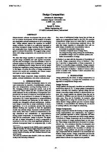
Design Components Representation Formal (Prolog) Description of Design Components Integration Instantiation Structural Design Knowledge
Prolog Evolution
Domain Knowledge
Generation Implementation
Figure 1. The Design Process 160
Appeared in the Proceedings of the IEEE 23rd Annual International Computer Software and Application Conference, Oct. 1999
ing, we present the syntax and the meaning of the design primitives used in this paper1:
Figure 1 illustrates the main characteristics of the development process underlying our approach. The design components are represented in a declarative way using Prolog [4]. These representations are generic in the sense that they capture good design practice in a domain-independent way. The general declarative representations of design components are instantiated into concrete domain-specific representations to reuse good design practice. The concrete design components are integrated and the intra-component and inter-component anomalies or inconsistency properties are checked. An inter-component inconsistency occurs when a design component combination fails to meet some of its required combination properties, while an intracomponent inconsistency occurs when a design component fails to satisfy one of its internal properties. The evolution of the combined design component representations can incorporate new requirements. Furthermore, the design component representations in Prolog can be transformed into code templates by tools such as Draco-PUC [12]. It is worth mentioning that intuition and design experience also play an important role in this process as, for example, in the selection of the generic design components to be (re)used. In this sense, the information about patterns as described in many pattern catalogues is very useful [8].
2.1
class(C): C is a class. abstractclass(C): C is an abstract class. inherit(A, B):
B is a subclass of A.
attribute(C, A, V, T): V is the name of an attribute with type T in class C. A describes the access right of this attribute, i.e. public, private, or protected. method(C, A, F, R, P1, T1, P2, T2, ... ): F is a method of a class C. A describes the access right of this method. R describes the return type which is optional. The method’s parameters and their types are P1, T1, P2, T2, ..., respectively, and this part is optional. invoke(C, M’, O, M, P): The method M which belongs to the object O is invoked in the method M’ of the class C, where P is the parameter of the method M. P can contain zero or more parameters depending on the number of parameters that the method M has. member(E1, S1, E2, S2, ...): E1 is an element of set S1. E2 is an element of set S2, and so on. When universal quantification "forall" and member are used together, it enumerates set S1, S2, ..., Sn simultaneously, i.e. the first elements of all sets are enumerated at the same time first, then the second elements are enumerated in the same way, and so on.
2.1.2 Pattern Primitive Operators A higher level of abstraction is provided by introducing pattern primitive operators. Pattern primitive operators are represented in terms of design primitive operators and they allow general object-oriented schemas such as delegation, aggregation and polymorphism to be defined. Pattern primitive operators capture the sub-patterns occurring frequently in the declarative representation of design patterns. They can also be used to change or transform the patterns. In addition, these operators can assist with the evolution of the pattern schema and with the application of this pattern. As an example, a pattern primitive operator, called abstract coupling or polymorph, is represented in Prolog as follows:
Representation
As the initial phase, design components, such as design patterns, are represented in Prolog and stored in a Prolog database. There are several advantages of using Prolog as a repository of design knowledge. First, the representations of these components can be reused by instantiating the corresponding Prolog rules of each component when they are applied to produce a concrete domain-specific component representation. Second, the properties and constraints of each design component can be described as Prolog rules. These rules can be used to check the consistencies of the design components. Third, the addition and removal of structural facts about design components can be accomplished by using the Prolog assert and retract clauses. Fourth, the design component representations can be recovered through the Prolog deductive facilities [10].
polymorph(Interface, Imp, Binding, ConcreteImpSet, ImpOperation, Operation) :assert(abstractclass(Imp)), assert(method(Imp, public, ImpOperation)), forall(member(ConcreteImp, ConcreteImpSet), assert(inherit(Imp, ConcreteImp)) ), forall(member(ConcreteImp, ConcreteImpSet), assert(class(ConcreteImp)) ), forall(member(ConcreteImp, ConcreteImpSet), assert(method(ConcreteImp, public, ImpOperation))), assert(abstractclass(Interface)), assert(attribute(Interface, private, Binding, Imp)), assert(method(Interface, public, Operation)), assert(invoke(Interface,Operation,Binding,ImpOperation)).
2.1.1 Object-oriented Design Primitives Design components are represented in terms of objectoriented design primitives in a predicate-like format. Each design primitive consists of two parts: name and argument. The name part contains the name of an entity or a relation in object-oriented design, such as class, inheritance, etc. The argument part contains general information about an entity or a relation such as the information on the participants of an inheritance relation. In the follow-
extend_polymorph(Imp,NewConcreteImpSet,ImpOperation) :forall(member(ConcreteImp, NewConcreteImpSet), assert(inherit(Imp, ConcreteImp)) ), forall(member(ConcreteImp, NewConcreteImpSet), assert(class(ConcreteImp)) ), forall(member(ConcreteImp, NewConcreteImpSet),
1 A more comprehensive set of design primitives is described in [1, 6].
161
pattern is shown as follows. It uses the polymorph pattern primitive as a design sub-component.
assert(method(ConcreteImp, public, ImpOperation))). retract_polymorph(Imp,OldConcreteImpSet,ImpOperation):forall(member(ConcreteImp, OldConcreteImpSet), retract(inherit(Imp, ConcreteImp)) ), forall(member(ConcreteImp, OldConcreteImpSet), retract(class(ConcreteImp)) ), forall(member(ConcreteImp, OldConcreteImpSet), retract(method(ConcreteImp,public,ImpOperation))).
Interface
binding
Operation() o
bridge(Abstraction,Implementor,Imp,RefinedAbstractionSet, ConcreteImplementorSet,ImpOperation,Operation) :polymorph(Abstraction, Implementor, Imp, ConcreteImplementorSet,ImpOperation,Operation), forall(member(RefinedAbstraction,RefinedAbstractionSet), assert(inherit(Abstraction,RefinedAbstraction))), forall(member(RefinedAbstraction,RefinedAbstractionSet), assert(class(RefinedAbstraction)) ).
Imp
extend_bridge_abs(Abstraction, NewRefinedAbstraction):assert(inherit(Abstraction, NewRefinedAbstraction)), assert(class(NewRefinedAbstraction)).
ImpOperation()
binding
extend_bridge_imp(Implementor, NewConcreteImplementor, ImpOperation) :extend_polymorph(Implementor, NewConcreteImplementor, ImpOperation).
binding->ImpOperation()
ConcreteImpA
ConcreteImpB
ImpOperation()
ImpOperation()
retract_bridge_abs(Abstraction, OldRefinedAbstraction):retract(inherit(Abstraction, OldRefinedAbstraction)), retract(class(OldRefinedAbstraction)).
Figure 2. Polymorphism
retract_bridge_imp(Implementor, OldConcreteImplementor, ImpOperation) :retract_polymorph(Implementor, OldConcreteImplementor, ImpOperation).
The Prolog rules of polymorph represent the structure shown in Figure 2. The arguments of polymorph denote the generic elements, e.g., class, attribute or method. For example, Interface and Imp are abstract classes. Binding represents an object reference which is a state variable of the Interface class. ImpOperation and Operation are two important methods. ConcreteImpSet defines a set of concrete classes including ConcreteImpA and ConcreteImpB. This Prolog representation contains more information than the OMT representation as, for example, OMT can not represent an undetermined number of classes. This representation can also be seen as a possible solution to the impurity problem of design patterns discussed in [11]. The Prolog operators, assert and retract, are used to insert or remove certain facts into or from Prolog database, respectively. The forall predicate represents the universal quantification operator. It can quantify over a set of class names and add the corresponding facts about each class name into the Prolog database. For instance, the Prolog rule, forall(member(ConcreteImp, ConcreteImpSet), assert(inherit(Imp, ConcreteImp))), corresponds to the following first-order logic formula: 8ConcreteImp 2 ConcreteImpSet : inherit(Imp; ConcreteImp): The non-determinism in polymorph leaves space for evolution, i.e., for adding or removing concrete classes which inherit from the abstract class Imp. The addition or removal of one such class can be performed by the extend polymorph or the retract polymorph rules, respectively, which in turn assert or retract the corresponding facts related to the insertion or removal of this concrete class.
Abstraction Operation() o
imp
Implementor
imp->OperationImp()
OperationImp()
ConcreteImplementorA
RefinedAbstraction
ConcreteImplementorB
OperationImp()
OperationImp()
Figure 3. Bridge Pattern The main purpose of the Bridge pattern is to separate the abstraction from its implementation so that they can vary independently. Its OMT diagram is shown in Figure 3. Since Bridge pattern allows extensions of both the refined abstractions and the concrete implementations, there are two rules related to extend bridge and two rules related to retract bridge. In [1], we also provide another example of the Prolog representation of a design component, which we call the views-a operator [5, 3]. In [6], we have provided the Prolog representations of all design patterns in [8].
2.2
Instantiation
When a designer chooses a design pattern to solve a particular application problem during the actual design, he or she can save this design decision as facts in the Prolog database by applying the rules that correspond to the design pattern and using as parameters the domain specific names required by the application. In this way, the Prolog facts which represent the structural constituents of that design pattern component will be saved in the Prolog database. This process is similar to the instantiation of classes in object-oriented programming language, but, in our case, a particular application of the design pattern is being created.
2.1.3 The Bridge Pattern Structural Representation The Prolog representation of the design component related to the structural design information encoded by the Bridge 162
Unlike in the case of classes, however, design component instantiation does not involve only structural and behavioral design component information, but also requires documentation to be adjusted and extended to fit the context at hand.
2.3
gradually evolve. This may lead to a situation in which the new design no longer conforms to the properties that its design components must preserve. The manual discovery of the inconsistencies in design can be a difficult job without a formalism or tool support. The design component representations in Prolog allow us to take advantage of the deductive facilities of Prolog to automatically find the inconsistencies.
Integration
Integration stands for the assembly of design components into a software system. When a design pattern component is added into a Prolog database, this pattern is automatically integrated with all patterns previously stored in the database as long as there is no naming conflict. However, some other issues need to be considered during the integration phase. First, some classes/objects may play different roles when they are the shared parts of two different design patterns. We have to make sure that the generic elements in these shared parts are instantiated with the same names in the different corresponding Prolog rules. Second, the integration of two or more design patterns may cause undesired interactions among them because they share classes. Some properties or constraints of a design pattern may not hold after integration. In this case, integration is not allowed because of these constraint violations.
2.4
3 Case Study The case study is a simplified variant of the case study presented in [16] which deals with a general-purpose system sort. This application sorts lines of text from standard input and writes the results to standard output. A line is a sequence of characters terminated by a newline. Different sort algorithms, e.g. quick sort, insertion sort, etc., can be chosen at run-time or configured before the system is running. The result will be printed in the order specified by the user. The design of this application, shown in Figure 4, contains five design patterns: Adapter, Bridge, Factory Method, Iterator, and Strategy. To address the requirement for an interchangeable sort algorithm, the Strategy pattern was selected to encapsulate the different sort algorithms, e.g., quick sort, insertion sort, selection sort, etc. In this case, we only deal with comparison-based algorithms. Therefore, all algorithms need a function to compare pairs of elements which can be characters, numbers, file folders, etc. The Bridge pattern captures this issue since it decouples the abstraction (comparison) from its implementation (character comparison, number comparison, and folder comparison) so that they can vary independently. The Factory Method pattern defines an interface for creating objects, but lets subclasses (Char, Num, Folder) decide which class to instantiate. The Iterator pattern is used to print all sorted elements without exposing its underlying representation. If we have a library containing functions as, for example, the insertion sort, we can reuse some functions required in this design. Since the interface of the insertion sort method may not be compatible with the interface of SortStrategy method in the Algorithm class, the Adapter pattern is used to adapt the interface. In [6], we have provided the Prolog representations of the five design patterns previously mentioned. According to the design process shown in Figure 1, we instantiate each of five design pattern components using the domain knowledge of the system sort in a Prolog database. As represented in Section 2.1, the Bridge pattern structure is instantiated as bridge(algorithm, implementor, imp, fquick, insertion, selectiong, fchar, num, folderg, compareImp, compare) in Prolog. Other patterns are instantiated in a similar way. From the graphic design representation shown in Figure 4, it is hard to know whether all properties of each design component are preserved after the five design components
Evolution
Evolution is the activity of adding or removing design elements in existing design. It can happen before or after integration. The addition and removal of system parts should not violate the constraints and properties of design patterns. In the representation of design pattern applications, we provide Prolog rules on extending and retracting design patterns. Another way of extending an existing design component is through views-a operators which is described in [1]. A views-a operator can add extra functionality to an existing design, thus make it evolve.
2.5
Reasoning
Consistency checking is not an easy task when the informal notations are used. It requires intuition and experience. On the other hand, representing design components in formal logic notations allows us to describe the properties and constraints of each design component in a precise way, thus, to automatically check whether a component loses some properties after it is combined with other components. There are many reasons to check the consistency of design compositions. For example, when two components are combined, they may share some common parts which can play one role in one component, but another role in the other component. This situation may lead to an inconsistent combination. Moreover, an existing design may be modified and 163
strategy
imp
Sort
Algorithm
Implementor
Sorting() o Print()
SortStrategy()
Bridge Pattern
Compare()
imp->CompareImp()
strategy
imp
o
CompareImp()
Factory
Factory Method
Pattern Char
strategy->SortStrategy()
Num
CompareImp()
CompareImp()
Folder CompareImp()
Strategy Pattern
Quick
Selection
SortStrategy()
SortStrategy()
CreateFolder
CreateNum
CreateChar
CreateImp() o
CreateImp() o
CreateImp() o
return new Num
return new Char
return new Folder
Array
Adapter Pattern
arrayP ArrayIterator
Input() Print() Create() array
Iterator Pattern
First() Next() IsDone() CurrentIterm() arrayP
CreateImp()
Insertion SortStrategy() o lib
lib Library InsertSort() lib->InsertSort()
Figure 4. System Sort are assembled, and to analyze whether there are undesired interactions among design patterns used in this case by just reading the informal design descriptions and the OMT diagrams. In the following, we will show how our formalization allows us to find some undesired interactions among the design pattern components.
in Algorithm. Therefore, the Insert class (which has the role of an Adapter) must inherit from the Algorithm class (which has the role of a Target) and delegate to the Library class (which has the role of an Adaptee). This third constraint is expressed as: rule3(Algorithm, Insert, SortStrategy, Library):- inherit(Algorithm, Insert), method(Insert, public, SortStrategy), attribute(Library, public, lib, Library), invoke(Insert, SortStrategy, lib, InsertSort). In the context of Prolog, when we ask whether our system sort design satisfies all three rules, the Prolog answer is no. This means that there are undesired interactions among these three design pattern components. When we test both rule1 with rule2 and rule1 with rule3, no conflict is reported. However, when we try both rule2 and rule3, there is an undesired inconsistency. Thus, the composition of the Bridge pattern and the Adapter pattern does not preserve both rule2 and rule3. When we apply the Adapter pattern to reuse a library function, the integration of the Adapter pattern and the Bridge pattern violates the constraint of the Bridge pattern which separates the abstraction from its implementations and lets them vary independently. For example, if we want to add another type of implementation, e.g. string comparison, for the abstraction of compare, we have to worry about the insert sort since the library function of the insert sort may not support the implementation of string comparison. As we have discussed in section 2, one of the important qualities of good reusable designs is the ability to evolve. However, when we plug-in the Adapter pattern it impedes the well-behaved evolution of the Bridge pattern.
As shown in the top-left of Figure 4, the Algorithm class and its descendants are overlapping parts of the Strategy pattern and the Bridge pattern. The Algorithm class plays the role of Strategy in the Strategy pattern and it plays the role of Abstraction in the Bridge pattern. The Insert class is also an overlapping part of the Strategy pattern, the Bridge pattern and the Adapter pattern. The Insert class plays the role of one ConcreteStrategy in the Strategy pattern, the role of one RefinedAbstraction in the Bridge pattern and the role of an Adapter in the Adapter pattern. The main purpose of the Strategy pattern is to encapsulate a family of algorithms and to let the algorithm vary independently of the clients that use it. Therefore, it requires every ConcreteStrategy class to overwrite the SortStrategy method. This constraint can be captured in Prolog as: rule1(Algorithm, SortStrategy) :- inherit(Algorithm, Child), method(Child, public, SortStrategy). The Bridge pattern decouples the abstraction (Compare method in the Algorithm class) from its implementation (CompareImp method in the Implementor class). Therefore, the SortStrategy method uses the Compare method to compare pairs of elements without concerning about which kinds of elements are compared. This second constraint is a rule related to the Bridge pattern: rule2(Algorithm, SortStrategy, Compare) :inherit(Algorithm, Child), method(Child, public, SortStrategy), invoke(Child, SortStrategy, Child, Compare). The Adapter pattern adapts the incompatible interface of the InsertSort method in Library with the SortStrategy method
4 Related Work Keller et al. [9] described a methodical approach to design composition which was illustrated as a process within 164
a four-dimensional design space. Although our approach is also in the area of software composition, it focuses on the formal, declarative, transformational and property-based aspects of design composition. Pal [15] investigated the lawgoverned support for realizing design patterns. He defined some rules and constraints of design patterns. However, in his work the property checking is performed at implementation level. He did not discuss the interactions among different design patterns when they were integrated together. Other work on tool support for object-oriented patterns [7] also discussed the constraints of patterns. However, they worked on single pattern constraints at implementation level too. Our work emphasizes the interactions among different patterns when they are integrated. Formalizing design patterns [2, 13] can also be seen as related work. We are currently interested in pattern-based property checking at design level. Sullivan [17] used Z language to describe the properties of the Component Object Model (COM) and discovered the inconsistency of COM architecture standard and the mediator style.
[2]
[3]
[4] [5]
[6]
[7]
[8]
5 Conclusion
[9]
We have presented a pattern-based approach to designoriented software composition. The approach focuses on design components, i.e., components that capture architectural design information about the software system. Our approach can be seen as a lightweight application of formal methods to design component assembly. The approach has several advantages. First, it allows design patterns to be represented in a declarative way, thus packaged in tangible design components. Second, it provides mechanisms that allow these design components to be reused to form the software application: instantiation, adaptation, assembly, alteration, and generation. Third, being based on software transformations, it allows for automation to take care of low-level editing details and to allow changes to be succinctly directed and reliably performed. Fourth, it allows properties of combinations of design patterns to be checked. Our approach focuses on structural property preservation and evolution of design composition. We will address behavior properties in the future. Although not all patterns concentrate on structural information, we can also, in principle, use an extension of the approach we have describe in this paper to study the combination of design pattern components which are more behavior than structure-oriented. We are also interested in the effects of the non-functional properties in design component assembly.
[10]
[11]
[12]
[13]
[14]
[15]
[16]
[17]
References [1] P. Alencar, D. Cowan, J. Dong, and C. Lucena. An Evolutionary Approach to Structural Design Composition. Tech-
165
nical Report CS-99-16, Computer Science Department, University of Waterloo, 1999. P. Alencar, D. Cowan, and C. Lucena. A Formal Approach to Architectural Design Patterns. Proceedings of the Third International Symposium of Formal Methods Europe, pages 576–594, 1996. P. Alencar, D. Cowan, C. Lucena, and T. Nelson. Viewpoints as an Evolutionary Approach to Software System Maintenance. Proceedings of the International Conference on Software Maintenance, Bari, Italy, pages 260–267, 1997. W. Clocksin and C. Mellish. Programming in Prolog. Berlin : Springer-Verlag, 1987. D. Cowan and C. Lucena. Abstract Data Views: An Interface Specification Concept to Enhance Design. IEEE Transactions on Software Engineering, 21(3):229–243, March 1995. J. Dong. A Transformational Process-Based Approach to Object-Oriented Design. Master’s Thesis, Computer Science Department, University of Waterloo, 1997. G. Florijn, M. Meijers, and P. van Winsen. Tool Support for Object-Oriented Patterns. Proceedings of the 11th European Conference on Object-Oriented Programming (ECOOP), pages 472–495, June 1997. E. Gamma, R. Helm, R. Johnson, and J. Vlissides. Design Patterns: Elements of Reusable Object-Oriented Software. Addison-Wesley, 1995. R. K. Keller and R. Schauer. Design Components: Towards Software Composition at the Design Level. Proceedings of the 20th International Conference on Software Engineering, pages 302–311, 1998. C. Kr¨amer and L. Prechelt. Design Recovery by Automated Search for Structural Design Patterns in Object-Oriented Software. Proceedings of the Working Conference on Reverse Engineering, IEEE CS press, Monterey, Nov. 1996. A. Lauder and S. Kent. Precise Visual Specification of Design Patterns. Proceedings of the 12th European Conference on Object-Oriented Programming (ECOOP), pages 114–134, July 1998. J. Leite, M. Sant’Anna, and F. Freitas. Draco-PUC: A Technology Assembly for Domain Oriented Software Development. Proceedings of the third IEEE International Conference of Software Reuse, pages 94–100, November 1994. T. Mikkonen. Formalizing Design Pattern. Proceedings of the 20th International Conference on Software Engineering, pages 115–124, 1998. O. Nierstrasz and L. Dami. Component-Oriented Software Technology. Object-Oriented Software Composition, ed. O. Nierstrasz and D. Tsichritzis, Prentice Hall, pages 3–28, 1995. P. pratim Pal. Law-Governed Support for Realizing Design Patterns. Technology of Object-Oriented Languages and Systems (TOOLS), USA, pages 25–34, July 1995. D. Schmidt. Object-Oriented Design Patterns and C++ – Advanced C++ Features and Design Patterns. Lecture Notes, Washington University, pages 1–122, 1996. K. J. Sullivan, J. Socha, and M. Marchukov. Using Formal Method to Reason about Architectural Standards. Proceedings of the 19th International Conference on Software Engineering, pages 503–513, May 1997.