A Practical Tool box for System Level Communication Synthesis ∗
Denis Hommais, Frédéric Pétrot and Ivan Augé Équipe ASIM/LIP6 Université Pierre et Marie Curie Paris, France
[email protected] —
[email protected] —
[email protected] ABSTRACT This paper presents a practical approach to communication synthesis for hardware/software system specified as tasks communicating through lossless blocking channels. It relies on a limited set of templates that characterize the way data are exchanged between tasks realized either in software or in hardware. The templates are highly portable because their software part is implemented using the POSIX thread functions, and their hardware part is a hand crafted synthesizable module with a System VCI interface. These Interface Modules allow simple Virtual Component reuse since they not only implement protocol compatibility through the use of the System VCI/OCB standard but also system level communications through semantics widely accepted in the design community.
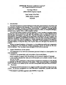
on the target architecture of Figure 1. Coprocessor
Coprocessor
Processor Vector Protocol
Master
Master/Slave
Master/Slave
VCI Wrapper
VCI Wrapper
VCI Wrapper
VCI protocol
On Chip Interconnect VCI Wrapper
VCI Wrapper
VCI Wrapper
Slave
Slave
Slave
VCI protocol
Vector Protocol
Memory
Coprocessor
Coprocessor
1. INTRODUCTION System-level specifications are often available under the form of communicating sequential processes. Each process uses blocking primitives to read and write data through mono-directional lossless channels usually organized as FIFOs. This model, known as Kahn processes network[12] is well suited for the description of embedded systems [10, 4, 7] and is the natural entry of HW/SW Codesign frameworks[11, 1, 16]. It relies on the classical read(channel, buffer, size) and write(channel, buffer, size) primitives, where channel is a point-to-point link identifier and buffer is an ordered set of size items. Since the primitives are blocking ones, the content of
Figure 1: Target system We first present the generic communication model used by Brunel et al.[3] during the COSY project. Based on this model, we describe some representative communications templates to perform data exchanges efficiently, for a producer in SW or HW to a consumer in SW or HW. The templates are then analyzed to determine the respective responsibilities of the software and the hardware to physically perform the communication, with the constraint of defining the minimum hardware support necessary for their implementation.
the buffer may not be altered during their execution. The process that writes into the FIFO is called the producer and the one that reads from the FIFO the consumer.
2. COMMUNICATION SYNTHESIS Generic Model for FIFO Channels Communication
This paper deals with the synthesis of the communications from such a specification to an actual hardware/software implementation
Communication through a FIFO channel means performing 4 actions:
∗ This work has been funded in part by the COSY 25443 Esprit Project.
1. Data transfer between both channels ends. The process knows a lower bound on the number of items that can be transfered by reading the FIFO status, thus no lock of the FIFO is necessary to perform the transfer, 2. FIFO status shared variable update by the reader and the writer. This is a variable shared by the producer and the consumer, therefore concurrent accesses shall not occur, 3. Blocking a task when it cannot perform the required operation due to lack of full (when reading) or empty (when writing) FIFO slots,
4. Awaking a task when either data or slots are available, allowing a blocked operation to resume.
VC, the interrupts handling, the system address map, ..., that are system and communication implementation related,
The way these actions are performed clearly depends on the HW or SW nature of the processes and on their implementation. The task of communication synthesis as we define it consist in mapping a given channel – i.e perform all the above operations – onto one predefined communication template.
• The user that wants to try other communications means, like an other bus standard, a point-to-point connection, or even simply another manner of using the communication resources doesn’t have to express these details in the behavior of the component. This allows easy exploration of the communication means without the need of modifying the behaviors and resynthesizing the coprocessors.
The general approach is inspired of the one presented in [8, 13], that however doesn’t give any detailed information on how synchronization is performed. Our contribution is to formalize more clearly what data transfers are made from in a multi-tasks, multiprocessor environment, and to present practical templates for them.
CLK REQ
DIN
Both the HW and SW parts of the template are parts of a library, and are instanciated as is, without any protocol synthesis or code generation. This allows optimized implementation that could hardly be automatically done (see for exemple the implementation of split transactions on the PI-Bus [14] in Section 3.3). [6] and others also use library components, but they glue them together through a synthesis process.
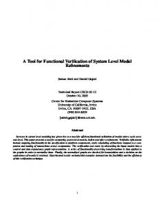
Communication architecture The target architecture of our communication synthesis contains one or several general purpose processors, several coprocessors that can be either master (initiator of a transfer) or slave (target of a transfer) on a System VCI compliant on chip interconnect. In software, communication synthesis is handled by the implementation of the read and write primitives using the POSIX threads. Accessing a FIFO buffer for reading or writing is a simple memory copy. However updating its status must be performed under the control of a mutex that warranties exclusive access to the variable. To access the shared variable, a mutex_lock must be performed. If the mutex is already locked, then the calling thread is blocked until it is unlocked by another thread using mutex_unlock. If data (resp. FIFO slots) are not available, the task uses cond_wait to be suspended until a condition (cond ) becomes true. The condition is changed by the producer (resp. consumer) thread with cond_signal once it has written (resp. read) the FIFO. The way the copy is performed depends on the template that is used to implement the communication. In hardware, we have chosen to use a communication protocol as close as possible to the read and write primitives, because these are used in the task behavioral specification. We thus assume that a coprocessor that implements a task in hardware needs to perform blocking read and write operations. This requires the definition of a new protocol (we call it the vector protocol in what follows, and it is presented Figure 2), that must be used by the coprocessor. This also necessitate to define a hardware interface module that performs data transfer from a coprocessor that uses the vector protocol through the on chip interconnect and provides mechanisms to supports synchronization between the producer and the consumer. This choice of having a dedicated hardware interface is dictated by the following reasons: • The tool that synthesizes the task as a coprocessor doesn’t have to know about the bus protocol, the masterness/slaveness of the
3
LENGTH D0
D1
D2
D0’
STEP DONE
Figure 2: Timing diagram of a vector transfer This vector protocol is as follows. The coprocessor sets the number of items to transmit on the LENGTH lines and asserts the REQ signal. This is the hardware counterpart of the call of the software primitive. The STEP signal validates the data present on the DATA lines. When all items have been transfered, the DONE signal is asserted. This is the hardware counterpart of returning from the primitive. This protocol can be implemented with a two states FSM for each channel. To handle this protocol, the coprocessor must have an internal buffer. The absence of address (or index) lines allows to avoid dependencies regarding the buffer implementation, that can be random access or not. This protocol is point-to-point and the LENGTH signal is the size parameter of the communication primitive. All the details and complexity of the communication protocols are hidden in a hardware interface module and its software drivers. The module has a VCI interface to warranty interconnect level compatibility, and can be either initiator or target of a VCI transfer. VCI is a necessary but not sufficient condition to IP reuse, because at this level it is already necessary to have a common high-level communication setup between the VCs. One way of ensuring that is to define a set of communication templates and to build a programmable Hardware Interface Module to support them. This approach is quite different from the one from Borriello et al. [5] that generates dedicated hardware from waveforms and specific processor informations. They also implement the drivers from a device description, but do not specify which type of assumption they make on the underlying operating system. In our case we act at a more abstract level that requires a less automated approach. We demand that the coprocessors play the vector protocol and that the operating system supports the POSIX threads.
3.
COMMUNICATION TEMPLATES
We present a few distinctive communication templates to outline the resources needed by the Interface Module. All these templates share a common concern: ensuring proper data exchange while minimizing tasks context switches, interconnect bandwidth usage and interrupt generation. The communication templates as exposed
here make no assumption about the nature of the interconnect (bus, circuit switching or packet switching networks).
threshold value. When the interrupt is raised, the handler executes a sem_post, a POSIX semaphores function that never blocks.
We present below one communication template per type of communication. Other can be though of, depending mainly on the amout of data and the size of each chunk of data to be transfered: it is likely that exchanging a frame or a pixel will not have the same constraints. All type of communication support FIFOs either in memory or in the interface.
The software implementations of both the write function and the task in charge of resuming the producer are presented in Figures 5 and 6. In these Figures, depth represents the number of slots of the FIFO (a constant known at hardware generation time), status is the number of currently filled slots in the FIFO, threshold is a resource used to generate an interrupt when the status of the FIFO reaches its value. itline is the interrupt line associated to the threshold of the FIFO used for the current transfer. The channel semaphore is used to grant access to a resource of the channel to either the producer or the consumer. status and threshold are registers of the interface.
3.1
SW to SW
The FIFO is in memory. This requires a kernel implementing the POSIX threads to run on the processor. As – almost – all current kernels are POSIX compliant, this is solely a compilation of the primitives for the target processor.
WRITE (channel, buf, size)
CPU
memory Bus
Figure 3: Software/Software communication
3.2
SW to HW and vice-versa
The FIFO can either be in memory or in the interface. We present here the case where the FIFO is in the interface, and we assume that the producer is a SW task and the consumer a HW coprocessor. (The opposite transaction is symmetrical.) The physical FIFO depth is not related to the size parameter of the primitive. Data is split by the SW driver into chunks that can be accepted by the interface. If the FIFO is in the interface, the status Copro CPU
Bus
Figure 4: SW/HW communication with FIFO in the interface is implemented in the interface itself and updated by the hardware. It is automatically incremented when a data is written by in the FIFO and decremented when the coprocessor reads a data using the vector protocol. We need a mechanism that can suspend the writing task when the FIFO is full. This allows other software tasks to run on the CPU while the producing task waits for slots to be available in the FIFO. Conversely, when some data are consumed by the coprocessor, we need a mechanism to resume the producing task so it can be rescheduled by the system. In the full software implementation of the task, we use a condition to stop and restart the task. The writing task is in software, so it wait on a semaphore by executing sem_wait, waiting for the consumer to read items from the FIFO. To wake up the task when slots are vacant, we need to change the semaphore state using sem_post. To do so, the interface module implements a programmable threshold that generates an interrupt when the FIFO contains at least as many empty slots as the
1 n ← size 2 forever 3 do p ← depth − status 4 m ← min(n, p) 5 for i ← 0 to m − 1 6 do fifo ← buf[i] 7 n←n−m 8 if n = 0 9 then break 10 threshold ← min(m, depth ) 11 UNMASK _ INTERRUPT (line) 12 SEM _ WAIT (channel) 13 return size Figure 5: write primitive for SW/HW communication Lines 4 to 9 perform the transfer from the producer to the consumer of at most m items to ensure that the producer will not be blocked busy waiting for the hardware. This splits the data into chunks of maximal size. Note that memcpy cannot be used here since the FIFO is visible as a single address in memory. Lines 10 and 11 set the threshold value and allow the interface to transmit an interrupt, in order to the task runnable again when sufficient data will be available in the FIFO. The value of threshold is the maximum acceptable by the hardware: all available slots or what’s left to transmit. This ensures the minimum number of interrupts and context switches necessary to perform the write. Lines 12 suspends the task. T HRESHOLD I NTERRUPT H ANDLER(channel) 1 MASK _ INTERRUPT(line) 2 SEM _ POST(channel) Figure 6: Handler resuming the producer in software Lines 1 to 3 mask the interrupt lines and acknowledge the interruption, and line 4 makes the scheduler aware of the fact that the suspended task can resume. Since there are no blocking primitives used in this handler, it is not necessary to create a task, thus avoiding the task creation/deletion overhead.
3.3
HW to HW
The HW/HW template that we present here also has the FIFO in the interface, which is therefore a slave. The on-chip interconnect is a PI-Bus. We assume that the master is the producer and the slave the consumer for the sake of the explanation, but the template is completely symmetric.
Virtual Component
Virtual Component
Figure 7: Hardware/Hardware communication
FIFO
FIFO
Bus
Coprocessor
Vector Protocol
Initiator
Initiator
FIFO
Coprocessor
Copro
FIFO
Copro
Target
VCI Protocol Master p Wrapper
To start a transfer, the CPU configures the master with the slave address and the length of the transfer. It also ask the master to emit an interrupt once the transfer is over.
Slave p Wrapper
Master c Wrapper
WAKEUP
Slave Wrapper
c
Pi−Bus
It then starts the master interface. Let us now assume that the producer sends data at a high throughput and that the consumer reads slowly. The simple solution is to have the slave emits wait acknowledges on the on-chip bus. This, however, waste bandwidth and may even lead to a bus timeout, if the same slave needs to write data prior to read the one arriving on the bus. To avoid timeout (and in fact deadlocks), one can issue retracts. On the PI-Bus, the retract acknowledge informs a master that the slave is not yet ready to perform a transfer. Therefore the master must release the bus and make a new bus ownership request in at least 2 cycles, to allow arbitration among all masters. However, the bus will be very congested then, since many masters will compete for the bus only to see if they can resume their transfers. This waste bus bandwidth for the other masters that have indeed data to transfer (this is also an issue for packet switching on chip interconnects).
Figure 8: Implementation of the split transaction in the wrappers
An other solution is to have the master check the number of empty slots and send only this amount of data. This needs another master to fetch the FIFO status and clever hardware to build packets from them. This also need some way of asking the master to poll the slave status, either using an internal timer or a CPU request. This clearly isn’t viable for high performance communications.
3. The interface module must be modular to grow with the number of channel needed by the coprocessor plugged on top of it.
The last solution is to use split transactions, but then the slave has to re-initiate the transaction. Some busses, like the AMBA bus, define how to perform split transactions. Unfortunately this is not the case of the PI-Bus, thus we have to provide an implementation that conforms to the standard and supports this behavior. For the PI-Bus, we propose is a simple form of split transaction, implemented in the bus wrappers. We index p the actors on the producer side and c the ones on the consumer side. The masterp is coupled to a slavep , and the slavec is coupled to a masterc . Masterp tries to write into a full FIFO. Slavec issues a split acknowledge and masterp goes into a frozen state, waiting for a wakeup signal to become true. When the condition for which slavec sent a split is no longer true, masterc writes into slavep at a specific address. This activates the wakeup signal, and masterp can resume its transfer. Note that masterp doesn’t know how many slots are available in the FIFO, but since the coprocessor on top of slavec makes vectorized read requests, it is very likely that the adequate number of data will be transfered at once. This handshake is quite sophisticated and requires additional hardware within the FIFOs and the wrappers. It is however necessary to avoid using the CPU during a HW to HW transfer and to avoid wasting bandwidth because of the use of wait or retract states.
4.
HARDWARE INTERFACE ARCHITECTURE
Three considerations have been retained for the architecture of the interface module: 1. The module must be usable on target interconnects with different protocols and different size and timing constraints, 2. The module must be able to cope with different communication strategies,
Point 1 is achieved by the use of the System VCI standard, that allows to plug the interface on top of VCI compliant wrappers. We have performed this operation for PI-Bus based system developed by Philips [2] and on an packet switching network [9]. Point 2 is achieved by the definition of several communication templates that covers a wide range of uses, and by the use of these templates to define the resources necessary to implement the communications. Point 3 is achieved by the implementation of the Interface Module as a generic VHDL RT level synthesizable core. The Figure 9 shows the internal architecture of the Interface Module and its bus wrappers. The interface module has two VCI interfaces. One is a target to act as a slave on the bus and one is an initiator for bus master access. Behind the VCI interface, three kinds of module are needed to support the communication templates: a slave module, a master module and a interrupt source. From the tasks point of view, a task has always the initiative of a data transfer, because the task calls a primitive when it needs to read or write data. The vector protocol also follows this semantic. Between the coprocessor and the interface module, the coprocessor also always has the initiative of the transfer, but its initiative is bounded to reading or writing a given internal FIFO of the interface module.
PI−Bus
Vector protocol
Master wrapper
Master FIFO address generator
VCI initiator
VCI
Vector protocol Master FIFO address generator Slave FIFO
VCI target
VCI Slave wrapper
Vector protocol Slave FIFO
5.
RESULTS
The Interface Module can be parameterized in term of number of submodules: up to 8 slave modules and up to 2 master modules. Each submodule can be parameterized independently in term of data size, FIFO depth and interrupt generation. The Interface Module has been described in C for cycle true simulation under CASS[15] of complete systems. This allows to evaluate the performance of each template accurately.
ce ss ro
Interrupt Source
C op
ce te rfa In
W
ra pp
er
s
or
Vector protocol
interrupts can be individually and atomically masked. The processor can get the status of each interrupt line and an acknowledge can be send to the interrupt requester when the vector is read.
Interruptions
Figure 9: Hardware Interface Module architecture
The slave module contains the FIFO of the communication channel. Depending on the direction of the channel, the coprocessor reads (or writes) in the FIFO using the vector protocol. The slave module FIFO can be accessed through the bus slave wrapper and the VCI interface, by any master on the bus. Three other resources used by the communication templates are be addressed in the slave module: the FIFO status register that give the number of filled slots in the FIFO, the threshold interrupt generator that raises an interrupt when the number of filled slots is equal to a value programmed by software, and an address used for the implementation of the split transactions. The master module is used when the internal FIFO is not the target of the primitive: the interface module must fetch or store data in a memory or in another interface module as a master on the system bus. but the coprocessor does not have any knowledge on address map. The master module must generate address to access the memory or a FIFO in another interface module. To do so, the master module provides a programmable address generator. This address generator can be configured by the software to address a FIFO in an interface module or a circular buffer, that is a FIFO in memory. The parameters of this address generator are the first address of the transfer, the address of the last item (for a circular buffer), the increment to add to the current address to get the next one, the total length of the transfer to access only a finite number of data. It can also generate, upon request, an interrupt to inform the processor that the transfer is over. The support for the split transaction is mainly the responsibility of the wrappers, as illustrated Figure 8, that uses the naming convention of the previous section. However, the interface itself must provide a mechanism to inform the wrapper that a given slave has data available. The interrupt source receives the interrupt request of the other submodules to send only one request to the processor. When the processor receives the interrupt, it reads a vector in the interrupt source. This vector is the one that corresponds to the active interrupt with the highest priority. A vector is a 32 bits register that can be initialized by the processor at boot time. In the interrupt source, the
The interface module and the software drivers have been used to implement a system realizing real time jpeg picture decoding whose task graph and full software implementation is represented Figure 10.(a). The system (with a r3000 as processor), must run at 1.2GHz to reach 25 pictures per second. Using our approach, we have realized the architectures and mappings of Figure 10. For realtime decoding, Figure 10.(b) should run at 613MHz, Figure 10.(c) at 473Mhz and Figure 10.(d) at 16 Mhz. This example has shown that our tool box allows to switch communication templates and task mapping (HW or SW) easily. This implentation can be compared with an ad-hoc design of the same specification. Using the proposed approach to communication synthesis has allowed simple design space exploration by performing different mapping of the tasks and communications. For the same HW/SW partitionning (Figure 10.(d)), it has produced results of comparable performance (14MHz vs 16MHz), with less buffers than the ad-hoc approach, in a much shorter time frame. For actual hardware, a generic synthesizable RT level VHDL model has been designed. The synthesis of a module with the following configuration : 2 slave FIFO (twice 22 slots) and 2 masters (twice 12 slots) needs 11000 gates, 0.7 mm2 in 0.18µm, and has a propagation time of 8ns.
6.
CONCLUSION
Based on the general, system level, blocking read/blocking write communication model, we have defined a practical approach to communication synthesis. On the one hand, it relies on the use of the POSIX threads for the implementation of the software drivers, hiding the complexity of communication to the end-user. On the other hand it makes use of a hardware module that provides the required resources to implement a large number of communication templates. These templates have been chosen because they allow to implement communication between tasks mapped either on software or hardware efficiently, while minimizing resources usage. The module is compliant with the System VCI standard, allowing its use over many on chip interconnects. During the COSY project, these hardware modules have been used by Philips, with Philips own templates, as target for the communications mapping by Cadence VCC. We also have developed C simulation models for Philips TSS [17] and UPMC CASS simulators so to allow cycle true simulation of the resulting system.
ACKNOWLEDGMENT The authors would like to thank J.-Y. Brunel and W. M. Kruytzer of Philips Research for their invaluable cooperation and inputs during
IQ
ZZ
IDCT
VLD
threader IQ
RAMDAC
TG
vcims
vcims
ZZ
VLD
RAM DC
LIBU
DEMUX
vcims
TG
MIPS
IDCT
MIPS
LIBU
DEMUX
IC
mw
sw
mw
DC
System Initialization
sw
mw
sw
BCU
TG
BCU
System Initialization
mw
(a) IQ
IC
sw
mw
sw
vcims
vcims
RAMDAC
TG
RAM
(b)
ZZ
libu
idct
VLD
DEMUX
threader
threader
vcims
vcims
MIPS TG System Initialization
DC
IC
mw
sw
mw
vld
ZZ
idct
libu
threader
threader
threader
threader
vcims
vcims
vcims
vcims
IQ
sw mw
sw
mw
sw
mw
sw
mw
sw
mw
sw
BCU BCU
mw
sw
vcims
mw
sw
vcims
mw
sw
RAM
RAM vcims
DC
vcims
MIPS
RAMDAC
TG
(c)
RAMDAC
IC System Initialization DEMUX
TG
(d) Figure 10: Architectural exploration of the Multi-Jpeg system
the COSY project. P. Gomez of UPMC did the implementations of the JPEG decoder.
7. REFERENCES [1] BALARIN , F., S ENTOVICH , E., C HIODO , M., G IUSTO , P., H SIEH , H., TABBARA , B., J URECSKA , A., L AVAGNO , L., PASSERONE , C., S UZUKI , K., AND S ANGIOVANNI -V INCENTELLI , A. Hardware-Software Co-design of Embedded Systems - The POLIS approach. Kluwer Academic Publishers, 1997. [2] B RUNEL , J.-Y., DE KOCK , E., K RUIJTZER , W., K ENTER , H., AND S MITS , W. Communication refinement in video systems on chip. In Proceedings of CODES (Rome, Italy, May 1999), pp. 142–146. [3] B RUNEL , J.-Y., K RUIJTZER , W. M., K ENTER , H. J. H. N., P ÉTROT, F., PASQUIER , L., DE KOCK , E. A., AND S MITS , W. J. M. Cosy communication ip’s. In 37th DAC (Los Angeles, CA, June 2000), pp. Pages 406–409. [4] C ALVEZ , J.-P. Embedded Real-Time Systems. John Wiley & Sons, 1993. [5] C HOU , P., O RTEGA , R. B., AND B ORRIELLO , G. Interface co-synthesis techniques for embedded systems. In Proceedings of the IEEE/ACM ICCAD (San Jose, CA, Nov. 1995), pp. 280–287. [6] DAVEAU , J.-M., M ARCHIORO , G. F., B EN -I SMAIL , T., AND J ERRAYA , A. A. Protocol selection and interface generation for hw-sw codesign. IEEE Transaction on VLSI Systems, Special Issue On Design Automation of Complex Integrated Systems (Mar. 1997). [7] G AJSKI , D. D., VAHID , F., NARAYAN , S., AND G ONG , J. Specification and Design of Embedded Systems. Prentice Hall, 1994.
[8] G AJSKI , D. D., VAHID , F., NARAYAN , S., AND G ONG , J. Specification and Design of Embedded Systems. In [7], 1994, ch. 8, pp. 355–370. [9] G UERRIER , P., AND G REINER , A. A generic architecture for on-chip packet-switched interconnections. In Proceedings of DATE (Paris, France, Mar. 2000). [10] H OARE , C. A. R. Communicating Sequential Processes. Prentice Hall, 1985. [11] J.T. B UCK , S. H A , E. L., AND M ESSERSCHMITT, D. Ptolemy: A framework for simulating and prototyping heterogeneous systems. International Journal of Computer Simulation 4 (Apr. 1994). [12] K AHN , G. The semantics of a simple language for parallel programming. In Information Processing 74 (Stockolm, Sweden, Aug. 1974), pp. 471–475. [13] K ALAVADE , A. System-Level Codesign of Mixed Hardware-Software Systems. PhD thesis, Electronics Research Laboratory, Berkeley, 1995. [14] O PEN M ICROPROCESSOR SYSTEMS I NITIATIVE. OMI 324: Pi-Bus, Apr.-May 1996. [15] P ÉTROT, F., H OMMAIS , D., AND G REINER , A. Cycle precise core based hardware/software system simulation with predictable event propagation. In the 23rd Euromicro Conference (Budapest, Hungary, Sept. 1997), IEEE, pp. 182–187. [16] S ANTARINI , M. Cadence adds system-level design tool to eda flow. EETimes (Jan. 2000). [17] T HEEUWEN , F. System simulation at philips research. Talk at the MEDEA Workshop on System Simulation, May 1998.