BwayAt42nd (the intersection of Broadway and 42nd Street) is an individual be- ... source VideoCameraBway-42nd, a video camera located around Broadway ...
A Semantics-based Middleware for Utilizing Heterogeneous Sensor Networks Eric Bouillet, Mark Feblowitz, Zhen Liu, Anand Ranganathan, Anton Riabov, and Fan Ye IBM T.J. Watson Research Center, Hawthorne, NY 10532, USA, {ericbou, mfeb, zhenl, arangana, riabov, fanye }@us.ibm.com
Abstract. With the proliferation of various kinds of sensor networks, we will see large amounts of heterogeneous data. They have different characteristics such as data content, formats, modality and quality. Existing research has largely focused on issues related to individual sensor networks; how to make use of diverse data beyond the individual network level is largely unaddressed. In this paper, we propose a semantics-based approach for this problem and describe a system that constructs applications that utilize many sources of data simultaneously. We propose models to formally describe the semantics of data sources, and processing modules that perform various kinds of operations on data. Based on such formal semantics, our system composes data sources and processing modules together in response to users’ queries. The semantics provides a common ground such that data sources and processing modules from various parties can be shared and reused among applications. We describe our system architecture, illustrate application deployment, and share our experiences in the semantic approach.
1
Introduction
Increasingly ubiquitous sensors and sensor networks bring us data sources of various content, formats, modality and quality. They provide vast amount of information about events and phenomena in the physical world. Current sensor network research has mostly focused on issues pertaining to individual sensor networks. As a result, many applications are tied closely to one or a few sensor networks. Large numbers of diverse data sources, however, present the opportunities for new kinds of applications that utilize many data source simultaneously, thus achieving functions not possible by using any single sensor network. Consider the following motivating scenario. Local, state and federal transportation departments deploy cameras, motion / magnetic detectors and temperature sensors along highways and roads. Individually, each data source (i.e., a sensor or sensor network) provides traffic information with limited geographic coverage, sensing modality and data quality. None of them can individually satisfy the diverse needs: drivers want real time driving instructions; the Highway Patrol wants videos of accident scenes or plates of speeding vehicles; the Department of Transportation wants long-term traffic statistics for road expansion
plans. These applications require the use of heterogeneous data sources in an integrated manner. In this paper, we propose a semantics-based approach to this problem and describe a system that constructs such applications on the fly. These applications ingest data from many distributed, heterogeneous sensors and sensor networks. They use interconnected software modules (called Processing Elements (PEs)), which take data of certain content and format, and perform various operations, from elementary filtration to complex analysis. Finally they produce the highly summarized end results needed by users. Our approach is based on the use of ontologies, a formal method for describing the terms and relations relevant to a certain domain of interest. In our system, we use ontologies described in OWL [1], a standard representation language in the Semantic Web. Descriptions of data sources, PEs and users’ queries use the terms and relations defined in the OWL ontologies. Data sources are described by the semantics of typical data objects they produce; PEs are described by the semantics of data objects they consume and produce; queries express the semantics of end results users desire. An AI planning algorithm, enhanced to utilize semantic descriptions, automatically composes appropriate data sources and PEs together as applications that answer users’ queries. Automatic construction of applications based on formal semantics has many advantages. With diverse and heterogeneous forms and content of sensed data, and large numbers of PEs, the composition of such applications becomes a grand challenge. It is infeasible for a human user to sort out, from thousands of sensor data sources and PEs, which ones are appropriate for his needs, and the correct and efficient ways to interconnect them. It is through the formal semantic descriptions of sources and PEs that the planning algorithm is able to compose them in legitimate and efficient ways so that they collectively produce meaningful end results. The formal semantics also enables the reuse of sources and PEs among applications. We envision many parties will provide data sources or PEs of various kinds. By tapping on the growing reservoir of data sources and PEs, more and more powerful applications can be built. Without a common ground for the description of sources and PEs, one party’s sources and PEs cannot be reused by others. We make several contributions in this paper. We propose a semantic model for the formal description of data sources and processing elements so that they can be reused. We also define the conditions for legitimate connection among sources and PEs, and devise an efficient semantic planning algorithm to the automatic construction of applications. We also build a system that implements these ideas and proves the feasibility of our approach. The rest of the paper is organized as follows. We give an overview of the system in Section 2. In section 3 we present the semantic model used to describe data sources and PEs. Section 4 explains how to use the semantic descriptions to construct applications automatically. Section 5 demonstrates an example ap-
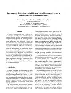
Fig. 1. The architecture of System S. Users submit inquiries to specify the end results they need. A planner constructs applications from data sources and PEs, whose semantics are formally described and stored in the ontology. A Data Source Manager (DSM) manages connections to data sources. Finally applications are deployed through Job Manager (JMN) and run on the underlying Stream Processing Core.
plication deployment. We compare with related work in Section 6 and conclude in Section 7.
2
System Overview
We have built our middleware of the semantics-based approach and deployed it in System S [2], which is a distributed stream processing system (Figure 1). Users submit inquiries that describe the formal semantics of desired end results. A planner constructs applications on the fly based on formal semantic descriptions of PEs and data sources. The sources are managed by a Data Source Manager component. Finally, applications are deployed by Job Manager (JMN) and executed on a Stream Processing Core (SPC), running in a cluster of machines. Our system interacts with sensors and sensor networks on the data level and lower level issues such as in-network processing are transparent to our system. As long as they can be accessed through some well-defined interface (e.g., a gateway or base station), they are treated as data sources providing data whose semantics can be formally described using ontologies. PEs perform different kinds of processing on data. Source PEs (denoted by “S” in Figure 1), a special type of PEs, talk the protocols of these data sources. They can access data sources and package raw data into internal Stream Data Objects (SDOs), a lightweight data container format that is used within the system and universally understood by all PEs. Finally Sink PEs (denoted by “D” in Figure 1) collect and deliver results to end-users. Our system uses a small set of commonly agreed upon ontologies. They can be defined through collaborative efforts, and can reuse existing ontologies from different domains, such as the NCI cancer ontology [3]; the GALEN medical
Data Sources
ontology [4], geographical metadata, dependable systems1 , etc. The problem of exactly how to define ontologies falls in the area of ontology engineering, which is not our focus in this paper. We focus on how to use ontologies for describing components and for the automatic construction of applications. To automatically construct applications, we need to address several critical issues: 1) How to formally describe the semantics of data sources and PEs; 2) How to decide the legitimate connection between PEs, i.e., which PEs’ output streams match the types and semantics of required input streams of other PEs; 3) how to compose PEs and form a processing graph that can produce the desired final results. Before we explain how we address these issues in the following sections, we use an exemplary inquiry to illustrate how it is processed in our system. Consider an inquiry that requests traffic congestion reports for a particular road intersection. The final flow graph depicting which PEs are used and how they interconnect to produce the results is illustrated in Figure 2. The system needs to know which data sources provide relevant data. A sound sensor and a Roadway Intersection Video Intersection Traffic Image video camera around that interVideo Image Pattern Sampler Intersection Camera Analysis section provide audio and video Traffic Congestion raw data from which congesJoin Roadside Intersection Sound Traffic Audio tion levels can be extracted. Sensor Pattern Analysis The system discovers relevant sources through their semantic Processing Elements descriptions. Similarly, the system needs to know which PEs Fig. 2. A Stream Processing Graph example can process such data. It can for an inquiry requesting traffic congestion reidentify an Audio Pattern Analport at an intersection. ysis PE from its semantics as taking roadside sound and producing traffic pattern. For video, two PEs (Video Image Sampler and Image Pattern Analysis) have to be connected to produce traffic pattern. The system needs their semantics to know they can be legitimately connected and produce meaningful results. Finally, a join PE is used to combine the results from the two chains of analysis.
3
Semantic Model of Data Sources and PEs
We use OWL ontologies [1] as the basis for the formal representation of the semantics of data sources and PEs. OWL ontologies describe concepts (or classes), properties and individuals (or instances) relevant to a domain of interest. A concept is the abstraction for a kind of entities sharing common characteristics. In the Traffic services example (Figure 3), Sensor, Location and MultimediaData are concepts. Individuals are specific entities that belong to certain concepts. Traffic Camera 10036-1 is an individual belonging to concept Sensor, and 1
http://protege.cim3.net/cgi-bin/wiki.pl?ProtegeOntologiesLibrary
Fig. 3. Example ontology in Traffic Services domain defining concepts like Sensor and Location, properties like capturedBy and atLocation, and individuals like BwayAt42nd BwayAt42nd (the intersection of Broadway and 42nd Street) is an individual belonging to concept Location. Concepts are associated with each other through properties that describe the relationship between them. Sensor and Location are related to each other through property atLocation, meaning that a sensor is lo-
cated at a certain location. Concepts may also have hierarchical relation among them via subclassOf relation. SoundSensor and Camera are subclasses of Sensor, and FixedPositionTrafficCamera is a subclass of Camera. The basic format for semantic descriptions is an RDF triple. An RDF triple consists of three components: a subject, a predicate and an object. The subject and object can be concepts or individuals, and the predicate is the property that associates them. RDF triples can describe OWL axioms and OWL facts, semantic information about concepts and individuals, respectively. For example, (Camera subClassOf Sensor) is an OWL axiom; and (TrafficCamera10036-1 atLocation BwayAt42nd) is an OWL fact. A set of RDF triples can be represented as a graph, called RDF graph. The nodes in the graph are subjects and objects in the triples, and the edges are predicates (properties) between them. One example is shown in Figure 3. 3.1
Descriptions of Data Sources
In our model, a data source produces a continuous stream of SDOs, each of which contains several data elements. A data source’s semantics lists what data elements are contained in an SDO, and an RDF graph that describes the characteristics (or semantics) of the data elements. As an example (Figure 4), consider the semantic description of the data source VideoCameraBway-42nd, a video camera located around Broadway and the 42nd Street. It produces a stream Bwy-42ndVideoStream. A typical SDO in this stream contains two data elements: VideoSegment 1 and TimeInterval 1. The characteristics of these two data elements are described in the form of an RDF graph. The characteristics include the concepts they belong to and the values of various properties. For example, the data element VideoSegment 1 belongs to the concept VideoSegment and is captured by a camera Traffic Camera 10036-1,
Fig. 4. Semantic description of a camera data source describing the stream it produces, the data elements contained in the stream ( VideoSegment 1 and TimeInterval 1) and the properties of these data elements described as an RDF graph
which is a Fixed Position Traffic Camera and located at BwayAt42nd, the intersection of Broadway and the 42nd Street. Observe that a typical SDO is described as containing two typical data elements: VideoSegment 1 and TimeInterval 1. We refer to these typical data elements as exemplars, since they provide an example description of the elements in the stream. Actual SDOs in the stream may replace these exemplars by actual values. For example, they may have specific VideoSegment instances that share the semantics of the exemplar, e.g. they have the same values of the ofSubject and capturedBy properties. Exemplars are represented as individuals that belong to the special concept called “Exemplar”. Syntactically, we denote exemplars with a preceding double underscore (i.e. “ ” ). The RDF graph that describes the semantics of the stream is based on domain ontologies, such as the one in Fig 3. The domain ontologies provide the common “language” for the interoperability of sources from different parties. When they describe their sources using the same ontology, we are sure that the same term has exactly the same meaning, even if they come from different parties. To summarize, the semantic description of a data source (or its stream) is a pair, (D, G), where – D is the set of data elements contained in the typical SDO in the stream. These data elements are represented as exemplar individuals. – G is an RDF Graph that describes the semantics of the data elements on the typical SDO as a set of OWL facts. 3.2
Descriptions of PEs
A Processing Element takes some number of input streams and produces some number of output streams. We treat PEs as “black boxes” and describe PEs
Fig. 5. Semantic description of VideoImageSampler PE that takes as input a stream containing a video segment and a time interval and produces a stream containing an image and a time
through the semantics of their input streams and output streams. Each input and output is described by a stream pattern, which specifies the kinds of streams that can be fed to the PE as legitimate input, and the kinds of streams the PE produces as output. The stream patterns are defined using variables, which are represented with a preceding question mark (“?”). As an example, the VideoImageSampler PE in Figure 5 is defined as requiring a stream whose SDO contains two data elements: ?VideoSegment 1 and ?TimeInterval 1. In addition, it specifies several constraints on the semantics of these elements. For example, ?VideoSegment 1 should be of type VideoSegment and ?VideoSegment 1 should be taken at ?TimeInterval 1, a certain time interval. When an input stream that satisfies these constraints is connected to this PE, the PE produces a single output stream that contains two exemplar data elements: Image 1 and Time 1. These exemplars are associated with a semantic description that describes their characteristics and also relate them back to the input data elements. E.g., ( Image 1 extractedFrom ?VideoSegment 1) means that Image 1 element in output stream is extracted from the video segment element ?VideoSegment 1 in input stream. They also share the same subject ?subject. The input stream pattern describes the set of constraints that must be satisfied by any stream that can be legitimately connected as input to the PE. It may be regarded as a semantic query that must be satisfied by the description of an input stream. The output stream pattern describes new streams produced by a PE as the result of connecting compatible input streams to the PE. We now give a formal definition of stream patterns. A triple pattern is an RDF triple where the subject or the object is a variable. An example is (?videoSegment 1 takenAt ?timeInterval 1). A graph pattern is a set
Fig. 6. Semantically matched data source and PE. The dashed lines show the variable substitutions that allow the input graph pattern of the PE to be embedded in the output graph of the data source, after DLP reasoning.
of triple patterns. A stream pattern has two elements: the set of data elements and their semantics. It is a pair of the form (V S, GP ) such that – V S is a set of variables and exemplars representing the data elements in a typical SDO in the stream. – GP is a graph pattern describing the semantics of the data elements. A PE is described as a 2-tuple of the form (hISRi , hOSDi) where – hISRi is a set of input stream requirements, where each input stream requirement is represented as a stream-pattern. – hOSDi is a set of output stream descriptions, where each output stream description is represented as a stream-pattern. There is a subtle difference between our use of variables and exemplars. Variables (like ?VideoSegment 1) represent the elements in an input stream pattern, and they may be carried forward to the output stream pattern. Exemplars (like Image 1)represent those elements that are newly created by the PE in the output stream pattern. We have developed a language for representing the semantic descriptions of PEs and data sources called SGCDL (Semantic Graph-based Component Description Language). The language is based on OWL and allows importing various domain ontologies and using terms defined in these ontologies for describing PEs and sources. Due to space limit, we do not go into details in this paper.
4
Semantic Composition of Applications
Our model of PEs and data sources makes them amenable to composition using AI planning. The input and output stream-patterns act as preconditions and effects of the PE. A data source is considered to have a single effect, corresponding to the stream it produces. The problem now becomes composing PEs and data sources in a DAG-based processing graph that can produce a stream which matches the inquiry goal. Before we go into the details of the composition, we first specify the conditions for connecting a set of streams to a PE as input, and determining the description of the output streams of the PE.
4.1
Connecting a stream to a PE
A stream can be connected to a PE if the stream-pattern describing the PE’s input requirements can be matched to the description of the stream. The matching process involves finding a substitution of all the variables in the stream pattern such that it can be inferred from the stream. Definitions in the domain ontology can be used in the inference process. Let us first define the notion of a substitution of variables. A substitution function (θ : V → RDFT ) is defined from the set of variables (V ) to the set of RDF terms (RDFT ). For example, mappings defined in a possible definition of θ in the example PE include : θ(?videoSegment 1) = VideoSegment 1, θ(?timeInterval 1) = TimeInterval 1 and θ(?subject) = BwayAt42nd. The result of replacing a variable, v, is represented by θ(v). The result of replacing all the variables in a graph pattern, GP , is written as θ(GP ). Consider a stream-pattern, SP (V S, GP ) described by a set of variables, V S and a graph pattern, GP . Also, consider a stream, S(D, G), with a set of data elements, D, and a semantic graph, G, describing the elements. We define SP to be matched by S, based on an ontology, O, if and only if there exists a substitution, θ, defined on all the variables in GP , such that following conditions hold: – S ⊇ θ(V S), i.e. the stream contains at least those elements that the pattern says it must contain. – G ∪ O |= θ(GP ) where O is the common ontology and θ(GP ) is a graph obtained by substituting all variables in GP . |= is an entailment relation defined between RDF graphs, i.e. it defines a logical reasoning framework by which it is possible to determine whether the set of facts in the left hand side (i.e. G ∪ O) can be used to infer the set of facts in the right hand side (i.e. θ(GP )). One way of looking at the above definition is that the stream should be more specific than the stream pattern. The stream should have at least as much data and as much semantic information as described in the pattern. The use of reasoning allows matching streams to stream patterns even if they use different terms or graph structures. The exact logical reasoning that can be performed using OWL is some subset of description logics (DL), e.g. based on RDFS, OWL-Lite, OWL-DLP, OWL-DL [5], etc. At the minimum, the reasoning can involve determining a graph-embedding relationship, i.e. can the substituted graph pattern, θ(GP ), be embedded in the graph G. More sophisticated reasoning mechanisms allow inferring additional facts from G, which can then be used to determining the same graph-embedding relationship. Our matching system uses DLP reasoning [6], which allows making inferences based on subclass and subproperty relationships, symmetric, transitive and inverse property definitions, domain and range definitions, value restrictions, etc. An example of this process is shown in Fig 6. Here, the stream produced by VideoCameraBway-42nd Data Source is matched to the stream-pattern describing
the input requirements of the VideoImageSampler PE. The variables ?VideoSegment 1 and ?TimeInterval 1 are mapped to the exemplars VideoSegment 1 and TimeInterval 1 respectively. The dashed arrows show the variable substitutions. In order to make the match, the system must perform DL reasoning based on subclass and inverse property relationships defined in the domain ontology. For example, the triple VideoSegment 1 videoOf BwayAt42nd is inferred, since videoOf is declared to be an inverse property of hasVideoSeg in the ontology. Also, the triple VideoSegment 1 type VideoSegment is inferred, since TrafficVideoSegment is declared to be a subclass of VideoSegment. Once the inferences are done, it is clear to see that the substituted graph pattern can be embedded into the graph describing the stream produced by the camera; hence a match is obtained. 4.2
Automatic Composition of Applications
The goal of a composition process is to produce a processing graph that generates streams that satisfy some high-level information need. This high-level information need, or inquiry, is represented as a semantic stream pattern that describes the kind of data elements and their semantics that some user or application is interested in. This stream pattern becomes a goal for our planner. The stream pattern is represented in a syntax that is similar to SPARQL [7], a semantic query language for RDF. An example goal for real-time traffic congestion levels at the Broadway-42’nd St intersection is PRODUCE ?congestionLevel, ?time WHERE (?congestionLevel type CongestionLevel) , (?time type Time), (?congestionLevel ofLocation BwayAt42nd) , (?congestionLevel atTime ?time)
Note that this stream pattern does not contain any reference to the actual data elements, or their formats, in which the congestion level and time may be represented. This means that users can frame information needs without knowing the exact formats (e.g. Java classes) for different messages. They can describe the information need in terms of the semantics without having to know the syntax of the final messages. In previous sections, we defined the conditions under which two PEs can be connected to each other, based on the matching between the output streams and input stream patterns. At a high level, the planner works by checking if a set of streams can be given as input to a PE. If so, it generates new streams corresponding to the outputs of the PE. It performs this process recursively and keeps generating new streams until it produces one that matches the goal pattern, or until no new unique streams can be produced, or the plan size exceeds a pre-specified maximum size. We have developed a planner that employs a two-phase approach to generate plans. In the first phase, which occurs offline, it does pre-reasoning on the output descriptions of different PEs to generate additional facts about the streams produced by these PEs. The exact flavor of reasoning performed is OWL-DLP (Description Logic Programs), which is known to be decidable, complete and to take polynomial time.
The original and the inferred facts about components are translated into a language called SPPL (Stream Processing Planning Language) [8]. SPPL is a variant of PDDL (Planning Domain Definition Language ) and is specialized for describing stream-based planning tasks. It models the state of the world as a set of streams and different predicates are interpreted only in the context of a stream. The SPPL descriptions of different components are persisted and re-used for multiple queries. The second phase is triggered whenever an information request is submitted to the system. During this phase, the planner translates the query into an SPPL planning goal. It then calls SPPL solver [8] to produce a plan consisting of actions that correspond to components. The plan is constructed by recursively connecting components to one another based on their descriptions until a goal stream is produced. In our implementation, this plan is then deployed in the System S stream processing system [2]. The main reason for the two-phase planning process is to achieve scalability in the presence of possibly time consuming reasoning.
5
Experiments
In this section we measure the automatic composition capability with an application domain we call Realtime Traffic Services (RTS). Applications in RTS provide vehicle routing services based on the analysis of real-time data obtained from sensors. The target deployment testbed used in our experiments consists of four 4-way 3GHz Intel Xeon(TM) machines and five 2-way 2.4GHz AMD Opteron (TM) 250 machines, running the Linux Suse 9.3 operating system and interconnected with 1Gbs network cards via a Cisco Catalyst 6509 switch. The planner was running on a Pentium M 2Ghz laptop with 2GB of RAM. Figure 7 shows a screenshot of a tool that visualizes processing graphs deployed on the System S infrastructure. PEs are grouped by host, and represented with a distinct color for each inquiry. Semioval PEs represent the source (left semioval) and the sink PEs (right semioval) which interface the RTS stream processing application with external data sources and consumers. The figure depicts the processing graph for a route-update inquiry (i.e. an inquiry for the best route from the current location to the final destination). As described in previous sections, this processing graph is automatically composed by planner to satisfy a set of results prescribed by the inquiry. The automatic placement of the PEs to their respective hosts is coordinated by a separate resource management component not described in this paper. The PEs of the resulting graph are the analytic modules that receive the streaming data from the current vehicle location (source PE 2) and destination (source PE 3), extract the GPS coordinates of the vehicle location (PE 4), generate the K best potential travel corridors using information from a map database(PE 5), receive updates on traffic conditions in the relevant locations (PE 0), and decide on routes based on vehicle size (PE 6). The two main results of this inquiry are route updates for the vehicles (sink PE 7) and updates to a list of currently relevant locations (cached in PE 1) for which updates about traffic and other conditions are required.
b0607e0 0
6
CDB
VRD
b0605e0 2 VLOC 3 VDST b0610e0
7 VRR 4 EVL 5 PCG b0603e0
1 LDB b0601e0
Fig. 7. The flow graph for Route Update Service that takes as input the vehicle positions and destinations from source PEs 2 and 3 respectively, and outputs a best route (PE 7), and generates a list of locations to monitor(PE 1).
The RTS scenario contained descriptions of 19 PEs and 6 sources, described using 246 OWL classes, 156 OWL properties and 385 OWL individuals. In this ontology we specified on average 13 triple patterns to describe a PE input, and 23 triple patterns to describe a PE output, and each PE description used an average of 7 variables and 2 exemplars. The offline phase of the planner took 42.51 seconds. The planning times (in seconds) for several inquiries are presented in the table below, together with graph size (number of PEs and sensors): Inquiry Time Graph Size Get Best Route Updates from current locn (Fig. 7) 2.51 8 Get Traffic Conditions Update near current location 2.32 12 Get Weather Conditions Update near current location 2.15 12 Get All Conditions Update near current location 2.5 18 Get Conditions and Best Route from current location 2.33 19 The results show that the response time of the planner is consistently around 2.5 seconds, which is acceptable for an end-user submitting the inquiry.
6
Related Work
One closely related work is Semantic Streams [9], which allows users to pose queries based on the semantics of sensor data. It uses a Prolog-based language and defines logic rules that describe the semantics, such as the type and location of sensor data sources, and input/output of inference units (equivalent to PEs). While that model allows a highly expressive query language, scalability remains an open question, since Prolog logic programs can be undecidable. Our model uses OWL, based on description logics, which is known to be decidable. The computational advantage of OWL combined with the use of scalable planning algorithms allows our middleware to construct processing graphs quickly even
when there are a large number of PEs and data sources. The choice of OWL as the representation medium also allows utilizing the large number of existing ontologies that have been developed in the Semantic Web. Data sources and PEs described using these terms and relations will be easier to inter-operate than those that are developed without any such shared, common knowledge. Programming models for individual sensor networks have received much attention. TinyDB [10] proposes a SQL based query interface to extract data from sensor networks. Welsh et al. [11] describe “abstract regions” to support the programming of a collection of related sensors. Although a non-exhaustive list, the above mostly deal with programming within individual sensor networks. They are not designed for applications that utilize data from many sensor networks and apply complex processing on the data. Other efforts have focused on how to utilize data from large numbers of heterogeneous sensors and sensor networks. Hourglass [12] proposes an Internet based infrastructure to inter-connect geographically diverse sensor networks, where applications collect and process data from them. Medusa [13] propose architecture and systems for distributed data processing applications that take data from many geographically distributed sensor networks. They do not use a semantic approach, nor do they address the problem of automatic construction of applications from declarative, semantic queries. Various stream query languages and stream processing architectures have been proposed. Aurora [14] lets human users create a network of stream operators to process incoming data. TelegraphCQ [15] proposes a declarative language for continuous queries that uses relational operations and expressive windowing constructs. These systems process structured data using relational and sliding window operators. In contrast, our system supports complex processing of unstructured data, such as speech-to-text and image recognition. It is highly extensible and supports processing beyond relational and sliding window operators. Prior work on composition by planning in Grid and Web Services includes [16, 17]. The major difference of our work from web service composition is the emphasis on the semantics of the data. Semantic web service models like OWL-S only associate concepts in an ontology with inputs and outputs, while our model associates more expressive RDF graphs with variables.
7
Conclusion
In this paper we describe a semantics-based approach to automatically constructs applications that utilize data from heterogeneous sensors and sensor networks. We use a semantic model to formally describe desired end results, data sources and PEs. Given an inquiry, a planner can automatically compose relevant PEs and data sources to form applications. We have developed a prototype and have demonstrated its ability to flexibly construct applications in different domains and manage semantically rich and diverse sensors and sensor networks. The semantic model helps in describing the diverse formats and meanings of sensor data sources, and the nature of possibly complex processing needed by applications. It also separates processing functions from the query model. New functions can be added by enriching the ontology with semantic descriptions
of PEs; neither the query model nor the planner are affected. As our system continues to be applied in a wider range of application scenarios, we will continue to evaluate and improve this promising approach.
References 1. McGuinness, D., van Harmelen, F.: Owl web ontology language overview. In: W3C Recommendation. (2004) 2. Jain, N., Amini, L., Andrade, H., King, R., Park, Y., Selo, P., Venkatramani, C.: Design, implementation, and evaluation of the linear road benchmark on the stream processing core. In: SIGMOD’06. (June 2006) 3. National Cancer Institute Center for Bioinformatics: NCI thesaurus. http://www.mindswap.org/2003/CancerOntology/ 4. Rector, A.L., Horrocks, I.R.: Experience building a large, re-usable medical ontology using a description logic with transitivity and concept inclusions. In: AAAI. (1997) 5. Baader, F., Calvanese, D., McGuinness, D.L., Nardi, D., Patel-Schneider, P.F., eds.: The Description Logic Handbook: Theory, Implementation, and Applications. In Baader, F., Calvanese, D., McGuinness, D.L., Nardi, D., Patel-Schneider, P.F., eds.: Description Logic Handbook, Cambridge University Press (2003) 6. Grosof, B., Horrocks, I., Volz, R., Decker, S.: Description logic programs: combining logic programs with description logic. In: WWW’03. (2003) 48–57 7. Prud’hommeaux, E., Seaborne, A.: SPARQL Query Language for RDF. In: W3C Working Draft. (2006) 8. Riabov, A., Liu, Z.: Planning for stream processing systems. In: AAAI’05. (July 2005) 9. Whitehouse, K., Zhao, F., Liu, J.: Semantic streams: A framework for composable semantic interpretation of sensor data. In: EWSN’06. (2006) 5–20 10. Madden, S., Franklin, M., Hellerstein, J., Hong, W.: TinyDB: An acquisitional query processing system for sensor networks. TODS’05 (2005) 11. Welsh, M., Mainland, G.: Programming Sensor Networks Using Abstract Regions. In: NSDI’04. (March 2004) 12. Shneidman, J., Pietzuch, P., Ledlie, J., Roussopoulos, M., Seltzer, M., Welsh, M.: Hourglass: An Infrastructure for Connecting Sensor Networks and Applications. Technical Report TR-21-04, Harvard EECS Dept. (2004) 13. Zdonik, S., Stonebraker, M., Cherniack, M., Cetintemel, U., Balazinska, M., Balakrishnan, H.: The Aurora and Medusa projects. Bulletin of the Technical Committe on Data Engineering, IEEE Computer Society (March 2003) 14. Abadi, D., Carney, D., Cetintemel, U., Cherniack, M., Convey, C., Lee, S., Stonebraker, M., Tatbul, N., Zdonik, S.: Aurora: a new model and architecture for data stream management. The VLDB Journal (2003) 15. Chandrasekaran, S., Cooper, O., Deshpande, A., Franklin, M.J., Hellerstein, J.M., Hong, W., Krishnamurthy, S., Madden, S.R., Raman, V., Reiss, F., Shah, M.A.: TelegraphCQ: Continuous dataflow processing for an uncertain world. In: CIDR’03. (January 2003) 16. Gil, Y., Deelman, E., Blythe, J., Kesselman, C., Tangmurarunkit, H.: Artificial intelligence and grids: Workflow planning and beyond. IEEE Intelligent Systems (January 2004) 17. M.Pistore, P.Traverso, Bertoli, P.: Automated composition of web services by planning in asynchronous domains. In: ICAPS’05. (2005)