This work proposes a framework based on the Semiotic. Engineering approach
that drives ... focusing on what he/she really wants to mean to the users. The
resulting .... with pre-defined concepts that guides designers to specify the
conceptual ...
A semiotic-based framework to user interface design Jair C Leite Rio Grande do Norte Federal University Natal, RN 59072-970 Brazil +55 84 215 3814
[email protected] ABSTRACT
This work proposes a framework based on the Semiotic Engineering approach that drives designers to specify the application conceptual model and its associated user interface. Our work contributes to user interface design by proposing the LEMD, a linguistic formalism to the user interface specification in an abstract and structured way focusing on what he/she really wants to mean to the users. The resulting specification could be mapped on conventional widgets. Keywords
User Interface Semiotics.
Design, Software Design, Computer
composed by user interface signs. The designer should create a good conceptual model and communicate it using an adequate repertoire of user interface signs. Our work presents the Semiotic Engineering Framework and the LEMD1. In this thought-provoking perspective, the User Interface (UI) is a message that communicates to users what they can do with an application and how they can use it. The LEMD is a user interface specification language designed to help designers in specifying the user interface as a message. LEMD is limited to the WIMP (Windows, Icons, Menus and Pointers) style for Graphical User Interfaces (GUI) used in several personal computers applications.
INTRODUCTION
THE SEMIOTIC ENGINEERING FRAMEWORK
In a landmark book, Winograd claims that it is necessary to move software development from a constructor’s-eye view to a designer’s-eye view to produce an artifact that works well for people in a context (Winograd, 1996). This vision emphasizes the software as a medium for the creation of virtualities that should allow users to produce quality results and to have a satisfying experience.
Eco’s Theory of Sign Production is our basic ground for the Semiotic Engineering. He proposes a framework of semiotic activities for sign production (Eco, 1976). Semiotic systems or codes are systems of types of signs (sign-types) that someone should use to produce a representamen to be interpreted as signs. Codes and languages are semiotic systems. A semiotic system has a basic structure. It has a system of sign-types - the syntactic model - and a system of semantic-types - the semantic model - that should be associated with the first.
The notion of virtuality is referred in the Cognitive Engineering approach as a conceptual model – the knowledge about system usability (Norman, 1986). Norman distinguishes the designer’s conceptual model from the user’s conceptual model that should be matched by interacting with the System Image. The system image is the external view that the user and the designer share to understand the conceptual model. Semiotic Engineering is a theoretically-based approach to user interface design in which computing systems are taken to be meta-communication artifacts (de Souza, 1993). By this we mean that interfaces are messages sent form designers to users and that such messages can, in their turn, send and receive messages Semiotics is the discipline that studies signs, signification and communication. The Semiotic Engineering approach reviews the software design problem as a communication problem. The user interface is a message and should be
The Semiotic Engineering framework follows this theory and propose a semantic model and a user interface model that should be mapped to each other as an incipient semiotic system. The Semantic Model
The application semantic model has two main components: the functional model and the interaction model. The functional model
The functional model is composed of Domain Information and Application Functions. The domain information refers to the entities that represent the domain objects. They refer to database records, document files, e-mail messages and several other objects that users know in their domain. They are represented in computer system as data structures in the programming level. The second conceptual entity of the functional model is the Application Function. An application function refers to a 1
LEMD is an acronym in Portuguese to Designer’s Message Specification Language.
complete process executed by the computer that changes the state of a domain information. From the user’s point-ofview, an application function is a computing service that realizes a use case. It is not an internal program function that implements something like a file opening or a window drawing. The interaction model
This model describes the main semantic types of the interaction process. The Basic Interactions are the actions users perform to interact with a widget. Examples of basic interactions are a click-on-a-button, type textual data, clickon-a-checkbox, select data from a list and view a result. Basic interactions are not atomic actions but something that users do using a widget. The Function Command specifies the way users enter information and control the execution of application function. Interaction results are user to provide feedback to users about function results or error messages. The Browsing Control is an optional component that is used to allow users to control another user interface objects. Pop-up and pull-down menus and the window minimization and maximization controls are examples of browsing control. The User Interface Model
Our work is considering just the GUI/WIMP user interface style. The mapping from the conceptual design representation to actual user interface objects requires a model to this style. To agree with the Semiotic Engineering perspective our model considers the UI has three main components: the Interface Signs, the Display Medium and the Activation Tool The basic abstract unit of our model is the Interface Sign. Interface signs are the widgets, icons, words, menus, dialog boxes, wizards (assistant) and all interface elements that can convey messages. Interface signs convey designer’s message to users and are also a medium to the interaction activity. In the most design tools the designer has a repertory of interface sign-types to create the concrete user interface message. There are some more specific type of Interface Signs: Object, Controller, Environment, Panel, Recipient, Selector and Presenter. These sub-types are used to provide a refined mapping to actual user interface signs. The widgets provides in most design tools may be classified as one of these types. The Display Medium is the physical medium where all interface signs are conveyed. The interaction activity happens through it. The display medium is usually the computer screen. The Activation Tool refers to any mechanism that can be used to perform actions using the interface signs in the
display medium. Users’ arms and fingers, mouse device, light-pens are examples of the activation tool. THE LEMD
In the Semiotic Engineering designers need a formalism that helps them to specify the UI as a message. A solution to this problem is to use the visual signs of GUI/WIMP – the widgets – as an expressive system to compose the UI message. However, these visual signs have no precise meanings. The designer needs to know what he/she wants to communicate – the content of the message. It is necessary to model the contents concepts using a semantic system and map them to the expressive elements. Another problem is that good software and interaction designers are not necessarily good graphical designers. They need a means to specify the application conceptual model in a more precise way. Concepts are abstract entities and they should be expressed by abstract models and not by concrete ones. Instead of working with visual sign-types, we argue that it’s better to work in a more abstract level. The LEMD is a language that allows the designer to express what he/she wants to communicate to user in a structured and abstract way. It is a formalism to designers to express their intentions on the conceptual level without any commitments with visual signs. Using LEMD, the designer specify each information is based on the following template:
domain
Domain-Info representation-type
It is only necessary to specify the name of the object and the type of representation. The LEMD has some basic representation types: number, name and finite set are examples. These basic types are supposed to cover the main structured data type used in computer systems and they are more appropriate on the abstract level of specification. The following sentences are the specification of domain information concepts used in the printer function example presented earlier. Domain-Info Number of copies representation-type number Domain-Info File Name representation-type name Domain-Info Printer representation-type finiteset-of name
The specification of an application function is constructed in LEMD as showed in figure 1. The LEMD requires the designer to specify the function name and other properties. The operands are the domain information elements that are used or affected by the execution of the function. The preand post-conditions define what should be true before and after the execution. These conditions are expressed in LEMD informally by using natural language statements.
Application-Function Printing Operands File Name, Printer, Number of copies Pre-conditions File name must be informed, Printer must be selected, Number of copies should be enter or the system print only one copy Post-conditions The printer should print the number of copies informed of the specified file name. Control Start, Stop, Pause, Resume, Cancel State Available, Running, Stopped, Finished
Figure 1: Specifying the printing function in LEMD
Specifying the functional model in LEMD is not very different to specify it using Use-Cases or other equivalent formalism. As in Use-Cases, an application function in LEMD is specified in a semi-structured way using a narrative language. However, the Use-Cases has very little concern to the interaction model. They do not allow designers to explicitly specify the interaction model. The designer should derive each application function from the tasks in a task model or from use-cases if the requirement has been specified using UML notation. Command-Message Print for Application-Function Printing Join { View Meta-Message “To print a document you must enter the information and then select one of the function control” Sequence { Join { Select { Enter Information-of File Name Select Information-of File Name } Combine { Select Information-of Printer Name Activate Show Command-Message Configure } Enter Information-of Number of copies } Select { Activate Start Application-Function Printing Activate Stop Application-Function Printing Activate Suspend Application-Function Printing Activate Continue Application-Function Printing Activate Waive Application-Function Printing } } }
Figure 2: Specifying the UI message to the print function
Using LEMD, a user interface command should be specified as a Command Message as showed in figure 2. This example is the specification of the user interface to a printing function. The mentioned structures and basic interactions have specific keywords that are employed in the message specification.
Mapping LEMD statements into UI signs
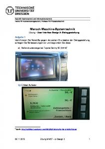
To be a practical formalism, the design representation constructed using LEMD should be translated into a concrete user interface. It is not our intent to provide an automatic translation because we believe that the human talent to creativity and visual communication is fundamental to assure a good communicability. It is the graphical designer that decides what user interface signs should be used. There is no formal meaning assigned to each user interface widget. The meaning emerges from its use through the time. The LEMD provides a semantic map the makes a correlation from the language keywords and statements to the interface signs. This semantic map may change if the meaning of the interface signs is not in agreement with those known by users. The table 1 shows the semantic map used in the example discussed in this paper. The combine is mapped into a frame widget, whereas the join structure is expressed by a visual grouping of interface signs, whereas. The select text keyword is mapped into a combo box widget and the enter text into a text box. The command button widget is usually used when there is an activate statement. The figure 3 shows how we mapped the specification of the print command message into its visual user interface. LEMD Statements
UI Signs (widgets)
Join {...}
Spatial configuration (visual grouping)
Sequence {...}
Spatial configuration and setting buttons label color attribute as gray meaning disable.
Combine {.. Frame widget Select Spatial configuration (visual grouping) {...} Select text
“Combo box” widget
Enter text
“Text box” widget “Spin box” widget
Enter number Activate
Command button
Table 1: The semantic correlation between the LEMD and UI signs. CONCLUSION
Semiotic provides a good insights and explanations to computing specially to user interface design. The Semiotic Engineering framework should be seen as a meta-model with pre-defined concepts that guides designers to specify the conceptual model and its correspondent user interface. This is firstly a change of paradigm and priorities that should be complemented by the cognitive and practical approaches. Whereas the cognitive approach provides for an individual perspective that focuses on learning,
understanding and other mental processes - no matter the intrinsic qualities of the object somebody is trying to understand - the semiotic approach provides for an interpersonal perspective focusing on interpretation and expression of meanings by scrutinizing communicative processes. They are complementary approaches to each other. Using LEMD the designer has a semantic model that helps him/her to structure what he/she needs to communicate to user. The LEMD is very flexible and has an expressive power. Its grammar is context-free that allows the composition of nested messages. It was designed to be used by humans, not by computers, so one of the main concerns is to provide statements that seem like the designer’s words. Since the LEMD is on the conceptual level, the designer focuses only in the essential aspects of the application functionality and interactivity without loosing control of its communicability. It considers not only static and aesthetical aspects of UI screen layout but also the performing and interactive aspects of the user interface medium. The LEMD provides constructs to help designers to specify their communicative intention about the interaction model. It allows designers to specify both functional and interaction models using the same formalism.
The LEMD and its associated framework follow the main advantages of the Semiotic Engineering design approach. It explains an important limitation: it is not possible to achieve determinism in design. It is not possible to warrant generic sign-types that are always interpreted by users as intended by designers. The model accommodates multiple users’ interpretations for the produced signs that are the base for an open conceptual model. The designer’s conceptual model is latent whereas user’s achieved one should match to it. REFERENCES
1.de Souza, C.S. The Semiotic Engineering of user interface language design, in Int. J. of Man-machine Studies, 1993. 2.Eco, U. A Theory of Computer Semiotics. Bloomington, IN: Indiana University Press, 1976. 3.Norman, D. “Cognitive Engineering”, in D. Norman and S. Draper (eds.), User Centered System Design, Lawrence Erlbaum Associates, NJ, 1986. 4.Peirce, C.S. Collected Papers. Cambridge, MA: MIT Press. 1931. 5.Winograd, T. (ed.) Bringing Design to Software. Addison-Wesley, 1996
Command-Message Print for Application-Function Printing Join { View “To print a document you must enter the information and then select one of the function control” Sequence { Join { Select { Enter Information-of File name Select Information-of File name } Combine { Select Information-of Printer name Activate Show Command-Message Configure } Enter Information-of Number of copies } Select { Activate Start Application-Function Printing Activate Stop Application-Function Printing Activate Suspend Application-Function Printing Activate Continue Application-Function Printing Activate Waive Application-Function Printing } } }
Figure 3: The mapping from LEMD statements to UI Sign.