7 Jan 2013 ... after pit closure [25–27]. Moreover, SURPAC could help metal mines to
effectively achieve digitization and informati- zation of mine design, ...
Hindawi Publishing Corporation Mathematical Problems in Engineering Volume 2013, Article ID 863104, 8 pages http://dx.doi.org/10.1155/2013/863104
Research Article A Simple Generation Technique of Complex Geotechnical Computational Model Hang Lin,1,2 Taoying Liu,1 Jiangteng Li,1 and Ping Cao1 1 2
School of Resources and Safety Engineering, Central South University, Changsha, Hunan 410083, China State Key Laboratory of Coal Resources and Safe Mining, China University of Mining and Technology, Xuzhou, Jiangsu 221116, China
Correspondence should be addressed to Hang Lin;
[email protected] Received 27 November 2012; Accepted 7 January 2013 Academic Editor: Fei Kang Copyright © 2013 Hang Lin et al. This is an open access article distributed under the Creative Commons Attribution License, which permits unrestricted use, distribution, and reproduction in any medium, provided the original work is properly cited. Given that FLAC3D (a geotechnical calculation software) is difficult to use for building large, complex, and three-dimensional mining models, the current study proposes a fast and a convenient modeling technique that combines the unique advantages of FLAC3D in numerical calculation and those of SURPAC (a mine design software) in three-dimensional modeling, and the interface program was compiled. First, the relationship between the FLAC3D and the SURPAC unit data was examined, and the transformation technique between the data was given. Then, the interface program that transforms the mine design model to calculate the model was compiled using FORTRAN, and the specific steps of the program implementation were described using a large iron and copper mine modeling example. The results show that the proposed transformation technique and its corresponding interface program transformed the SURPAC model into the FLAC3D model, which expedited FLAC3D modeling, verified the validity and feasibility of the transformation technique, and expanded the application spaces of FLAC3D and SURPAC.
1. Introduction Along with the rapid development of computer technology in recent years, the numerical method along with artificial intelligence technique has become an important mean of analyzing and calculating modern engineering technologies [1–6] and forecasting engineering stability and reliability [5, 7–9]. FLAC3D (numerical calculation software) has been extensively recognized and applied for analyzing geotechnical issues [10–12]. FLAC3D could be used to examine the changing rules of the field effect of rock mass from the macrotrend and it is suitable for most engineering mechanics issues, particularly for analyzing material elastoplasticity, large deformation, rheology prediction, and for geotechnical numerical simulation of construction processes [13–16]. However, FLAC3D is quite difficult to use for pretreatment modeling, particularly in the geological body of complicated multimedia and multiboundaries [17, 18]. Thus, engineers often use models by simplifications to approximately describe geotechnical models to solve this problem above. But different lithologies have different mechanical features excessive simplification of the model would reduce the reliability
of the numerical simulation results. On the other hand, the geology or mine design platform demonstrates good three-dimensional modeling, and it could accurately express the spatial distribution of the stratum and the geological structure with different lithologies [19–22]. A great progress has been made on simulation methods of complex geological interfaces and features, for instance, Xu et al. [17] suggested a 3D geological modeling technique (SGM) as a tool for constructing complex geological models in rock engineering, Wu and Xu [23] used a simple plane to simulate the fault or multiple combined planes to approximate the fault, for modeling geological faults in 3D, and Zhong et al. [24] presented an integrated 3D geological modeling methodology for modeling and visualization of large 3D geoengineering applications. But mine design is relatively independent of numerical calculation and analysis, and its function is generally limited to visualization and qualitative judgments. Thus, combining the advantages of the mine design platform in modeling and that of FLAC3D in numerical calculation and analysis is necessary. Recently, only few studies have been conducted on this combination.
2 The numerical calculation of a large mining project often involves complicated three-dimensional geological models. The current study takes the mine design software SURPAC with its powerful modeling function as the platform, builds complex three-dimensional models of mines, and automatically generates a FLAC3D model through data transformation to expand the application of FLAC3D into the numerical simulation of mine projects to solve the difficulties of FLAC3D modeling and to build accurate threedimensional mining models that can improve the reliability of simulation results and give play to the computational power of FLAC3D. Moreover, SURPAC could also expand its mechanical analytical ability based on its inherent functions such as data collection, storage, management, and inquiry to meet the requirements of an engineering model in prediction and decision support.
2. Development of the Model Transformation Procedure 2.1. SURPAC Modeling. The SURPAC serial software is a set of megadigitized mining engineering software with domestic leading level in minefields, and it is extensively applied to resource appraisal, geological measurement, mine design plan, production plan management, and reclamation design after pit closure [25–27]. Moreover, SURPAC could help metal mines to effectively achieve digitization and informatization of mine design, planning, and management. SURPAC has a complete set of three-dimensional modeling tools, and it could achieve complete imaging of mine exploration, three-dimensional geological modeling, the establishment of engineering database, open gallery and underground mine design, production and mining progress plans, tailing, and reclamation designs. Moreover, SURPAC has a powerful three-dimensional graphic system, and its core is composed of a totally integrated graphic module that has a complete set of visualization means and of data editing tools that visually generates and displays the three-dimensional structures of underground geology or mining areas, ground and terrain models, and other graphics. Moreover, it is an effective, convenient, and fast platform for building complex computational models. SURPAC adopts a polygon mesh to describe the physical borders of an orebody that forms during extraction, and block modeling is performed after the solid model is built. The solid model is a three-dimensional geometric model based on computer geometric shaping technologies, and it completely describes the spatial structure, geometric configuration, and spatial borderline of the lithology. A block, model includes a three-dimensional model consisting of common hexahedral blocks and it is the foundation for lithologic assignment and the subsequent numerical calculation. The basic idea is to divide the spatial geometric model of the orebody into a multitude of unit blocks and then to assign lithology values to the unit blocks that fill the entire orebody. 2.2. Brief Description of FLAC3D. FLAC3D is a numerical modeling code for advanced geotechnical analysis of
Mathematical Problems in Engineering 2 6
8
5
7
4
𝑠3 3 4 5
3 6 1
2
𝑠1
𝑠2
Face 1
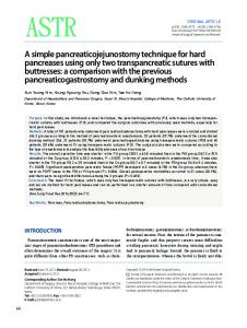
Figure 1: Data relationship between FLAC3D and SURPAC unit data.
soil, rock, and structural support in three dimensions [28]. FLAC3D is used in analysis, testing, and design by geotechnical, civil, and mining engineers. It is designed to accommodate any kind of geotechnical engineering project, where continuum analysis is necessary. FLAC3D utilizes an explicit finite difference formulation that can model complex behaviors not readily suited to FEM codes, such as problems that consist of several stages, large displacements and strains, and nonlinear material behavior and unstable systems (even the cases of yield/failure over large areas or total collapse). 2.3. Transformation of SURPAC and FLAC3D Data. SURPAC provides hexahedral unit shapes for treating units of simulated objects and it changes the sizes of the hexahedral units based on the features of the geological body, precision requirements of calculation, and spatial layout features of the unit shapes. Compared with the unit shapes in FLAC3D, the hexahedra units in SURPAC are known to correspond to block units. The information in a FLAC3D unit includes the three-dimensional coordinates of eight nodes (𝑝1 ∼ 𝑝8 ) in the unit and in the unit group. The information in the SURPAC unit includes a unit centroid (𝑥0 , 𝑦0 , and 𝑧0 ), sizes 𝑠1 , 𝑠2 , and 𝑠3 , and unit attributes. Figure 1 shows the mapping relationship between two types of unit nodes. The transformation technique of the unit node coordinates could easily be obtained through the geometric relationship, 𝑥0 − 𝑠1 , 2 𝑦 −𝑠 = 0 2, 2 𝑧0 − 𝑠3 = , 2
𝑥𝑝1 = 𝑦𝑝1 𝑧𝑝1
(1)
Mathematical Problems in Engineering
3
Root
Geological plan and profile views of mine
FLAC3D numerical calculation
2
Boundary condition mechanical properties
0 0
0
1
2
4
5
6
3
7
SURPAC software
34
FLAC3D model 35
6 30 32
7
37 33
Solid model
“Impgrid” importing model
30 31 32 33 34 35 36 37 Block model
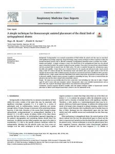
Figure 2: Unit subdivision.
where, 𝑥𝑝1 , 𝑦𝑝1 , and 𝑧𝑝1 represent the 𝑥, 𝑦, and 𝑧 coordinates of point 𝑝1 , respectively. The three-dimensional coordinates of points 𝑝2 ∼ 𝑝8 could be obtained using the same theory. Parts in the model that need special treatment are grouped together during FLAC3D calculation. Thus, the attributes of each unit is determined along with SURPAC modeling to transform the units with different attributes into different groups in the FLAC3D model. The specific implementation process is as follows: SURPAC builds a block model of the three-dimensional orebody during modeling, that is, three-dimensional dissection of the entity model of the orebody with squares or cuboids. The blocks are assigned with different attributes. SURPAC adopts a series of three-dimensional arrays to store information, such as grade and lithology, among others. The subscripts of an array correspond to the row, line, and layer number of blocks to save storage space and calculation time. However, SURPAC is inflexible to use because its coordinates rotate quite often during modeling. SURPAC has sharp contradictions in accurately fitting the borderline and the division grain size (storage) of a mine. Thus, the octree method was introduced to solve this problem, that is, continuously dividing the three-dimensional entity space into eight three-dimensional networks of the same size, with one or several attributes, as shown in Figure 2. The unit is continuously subdivided if the mesh is too big until the same area has a single attribute to meet the border of an orebody with different attributes. The border of a geological body could be simulated in form using continuous subdivision, and the mesh will have the attributes of a rock in such spatial position. Thus, the current study builds a three-dimensional geological model to reflect completely the geological structure, the spatial distribution of the lithology, and accurate geological information using continuous subdivision under multimedia complex conditions. Finally, the SURPAC block model generates STR files, which could be opened in text format. The data file has the following format. (1) Header message. (2) Centroid coordinates, sizes, and attributes of the units.
FLAC3D software Formula (1) coordinates transformation
Data text
Unit attributes transformation
“Impgrid” format FLAC3D data text
Figure 3: Model transformation flowchart.
The geometric parameters and attributes of the SURPAC units are read during data transformation. Then, the threedimensional coordinates of the FLAC3D unit are transformed in accordance with formulas (1) and are then grouped together. The group name is the attribute of the corresponding SURPAC unit. The numerical model could be rebuilt through the “call” command in FLAC3D to transform the data, but it will consume many computer hours in building the model because it faces a large amount of unit data. However, the “impgrid” command embedded into FLAC3D could import all the data at one time, which omits the remodeling process of FLAC3D and shortens the computer hours; for instance, the “call” command needs about three hours to build a threedimensional model with 10,000 units, whereas the “impgrid” command only needs less than a minute at the same computer. However, the “call” and “impgrid” commands have different call formats. The format of the “impgrid” command is as follows. (1) Node information. (a) ∗ GRIDPOINTS. (b) G Node No., Node Coordinate 𝑋, Coordinate 𝑌, and Coordinate 𝑍. (2) Unit information. (a) 𝑍 Unit Type, Unit Number, and Node Number contained by the unit. (3) Grouping information. (a) 𝑍 Group No., Unit Number contained by this group.
Mathematical Problems in Engineering
N
4
625 sections worked out area
605 sections worked out area
645 sections worked out area
in number 1 central mining area
in number 1 central mining area in number 1 central mining area
in number 1 central mining area
N
675 sections worked out area
560 sections worked out area in number 1 central mining area
N
580 sections worked out area in number 1 central mining area
440 sections worked out area in main mining area
420 sections worked out area in main mining area
N
480 sections worked out area 460 sections worked out area in main mining area in main mining area
400 sections worked out area in main mining area
N
480 sections worked out area 500 sections worked out area 520 sections worked out area in number 2 central mining area in number 2 central mining area in number 2 central mining area N
540 sections worked out area in number 2 central mining area
560 sections worked out area in number 2 central mining area
590 sections worked out area in number 2 central mining area
Figure 4: AUTOCAD plan view.
Based on the analysis of unit data relationship above, the current study uses FORTRAN to compile the interface program. First, the program transforms the data into the required data format. Then, the program calls in the data using the “impgrid” command of FLAC3D, and then
it sums the boundary condition, initial condition, and dynamic parameters of the soil body for calculations. Refer to Figure 3 for specific procedures. However, the model transferred from SURPAC can not make sure the grid of element meets each other, then the command “attach
Mathematical Problems in Engineering
5 1–675 m
2–590 m
1–645 m 1–625 m 1–605 m
2–560 m 1–605 m
1–580 m
2–540 m 2–520 m 2–500 m 2–480 m
480 m main 460 m main 440 m main 420 m main 400 m main
Figure 5: AUTOCAD vertical view.
640 560 480 400
Figure 7: Block model of SURPAC. 640
560 480
(m)
(m)
(a) The whole model
400
(b) The model of stope
Figure 6: Solid model of SURPAC.
face” in FLAC3D is needed to eliminate the errors of calculation.
3. Application of Model Transformation Procedure Given a large iron/copper mine and the complicated properties distribution of rock mass the owner provides AUTOCAD plan view of the mine, as shown in Figure 4 and AUTOCAD
vertical view of the mine, as shown in Figure 5, and the north direction of each view is inconsistent. If other software, such as ANSYS, is used to build the model, it needs to determine the three-dimensional coordinates of each border of the mine. Moreover, mistakes could easily occur because of the huge work volume. In contrast, SURPAC only needs to read the corresponding DXF files of the AUTOCAD drawings and rotate them into the consistent northern direction, which allows convenient and fast modeling and omits the work of choosing points and determining coordinates. A three-dimensional model was then constructed using FLAC3D with the transformation technique proposed in this paper and the modeling of the worked out section as an example. The specific procedures are as follows. (i) Building of the solid model. The AUTOCAD drawings are loaded first, and then the coordinates of each point in the graph are transformed into actual geographical coordinates based on the planar distribution of the prospecting line, the angle between the prospecting line and the east-west axis, and the scale of the
6
Mathematical Problems in Engineering
Group name 560 sections worked out area in number 1 central mining area 580 sections worked out area in number 1 central mining area 605 sections worked out area in number 1 central mining area 625 sections worked out area in number 1 central mining area 645 sections worked out area in number 1 central mining area 675 sections worked out area in number 2 central mining area 480 sections worked out area in number 2 central mining area 500 sections worked out area in number 1 central mining area 520 sections worked out area in number 2 central mining area 540 sections worked out area in number 2 central mining area 560 sections worked out area in number 2 central mining area 590 sections worked out area in number 2 central mining area 400 sections worked out area in main mining area 420 sections worked out area in main mining area 440 sections worked out area in main mining area 460 sections worked out area in main mining area 480 sections worked out area in main mining area (a) The whole model
(b) The worked out area model
Figure 8: FLAC3D model.
profile map. The specific scope of the lithology on each geological prospecting profile is sealed, and then it is linked up in sequence on different profiles. The outermost profile is then sealed to form an encapsulated three-dimensional entity [19], as shown in Figure 6. (ii) Building the block model. The spatial geometric model of the orebody is divided into a multitude of unit blocks as per the certain sizes of the blocks. Then, values are assigned to the unit blocks that fill the entire scope or orebody, and then the unit blocks of the block model are subdivided automatically at the physical border through the unit subdivision technologies to ensure that the block model simulates the geometric shape of the actual orebody, as shown in Figure 7. (iii) Generation of the FLAC3D model. The data file generated by SURPAC and the FLAC3D file generated by the interface program developed in the current study, that is, FLAC3D, are used, and the information of the entire model is imported through “impgrid,” as shown in Figure 8. Moreover, the unit subdivision resulted in the misalignment of the meshes in some regions, but the subdivision units and raw units have
integral multiple relationships, as shown in Figure 2. Thus, information transfer in misaligned areas of the meshes could be achieved through the attach face command in FLAC3D. After calculation by FLAC3D, the displacement and state contours are shown in Figure 9, which is in consistence with the real situation.
4. Conclusion (1) Considering the difficulty of using FLAC3D (geotechnical calculation software) for pretreatment modeling, the current study combined SURPAC (mine design software) and FLAC3D to utilize the advantage of SURPAC in simulating geological features and to provide a calculation model that conforms to the geological reality of FLAC3D. (2) The differences between the information from the two types of unit information, that is, SURPAC and FLAC3D, were analyzed, the data relationship between units was built, the data transformation technique was proposed, and the FORTRAN was adopted to compile relevant transformation procedures. (3) When the transformation technique proposed in the current paper was applied to the modeling of a given large
Mathematical Problems in Engineering
7
Contour of 𝑍-displacement Plane: on Magfac = 0𝑒 + 000
Block state Plane: on
−1.6239𝑒 + 000 to −1.5𝑒 + 000
None
−1.5𝑒 + 000 to −1𝑒 + 000
Shear-n shear-p
−1𝑒 + 000 to −5𝑒 − 001
Shear-n shear-p tension-p
−5𝑒 − 001 to 0𝑒 + 000
Shear-n tension-n shear-p tension-p
0𝑒 + 000 to 5𝑒 − 001
Shear-p
5𝑒 − 001 to 1𝑒 + 000
Shear-p tension-p
1𝑒 + 000 to 1.1743𝑒 + 000
Tension-n shear-p tension-p
Interval = 5𝑒 − 001
(a) The vertical displacement contour after calculation
(b) The state contour after calculation
Figure 9: The results calculated by FLAC3D.
iron/copper mine, it indicated that the proposed transformation technique and its corresponding interface program transformed the SURPAC model into the FLAC3D model, speeding up the FLAC3D modeling and verifying the feasibility and validity of the proposed transformation technique.
Acknowledgments This paper gets its funding from Project no. 20120162120014 supported by the Specialized Research Fund for the Doctoral Program of Higher Education of China; from Project no. 2013CB036004 supported by National Basic Research 973 Program of China; from Project no. 201201 supported by Open Fund of Key Laboratory of Mechanics on Disaster and Environment in Western China (Lanzhou University), Ministry of Education; Project no. 12KF01 funded by the Open Projects of State Key Laboratory of Coal Resources and Safe Mining, CUMT. The authors wish to acknowledge these supports.
References [1] S. Y. Chen, Y. J. Zheng, C. Cattani, and W. L. Wang, “Modeling of biological intelligence for SCM system optimization,” Computational and Mathematical Methods in Medicine, vol. 2012, Article ID 769702, 10 pages, 2012.
[2] Z. Z. Teng, J. He, A. J. Degnan et al., “Critical mechanical conditions around neovessels in carotid atherosclerotic plaque may promote intraplaque hemorrhage,” Atherosclerosis, vol. 223, no. 2, pp. 321–326, 2012. [3] S. Y. Chen, W. Huang, C. Cattani, and G. Altieri, “Traffic dynamics on complex networks: a survey,” Mathematical Problems in Engineering, vol. 2012, Article ID 732698, 23 pages, 2012. [4] K. M. Hosny and M. A. Hafez, “An algorithm for fast computation of 3D Zernike moments for volumetric images,” Mathematical Problems in Engineering, vol. 2012, Article ID 353406, 17 pages, 2012. [5] X. L. Yang and F. Huang, “Slope stability analysis considering joined influences of nonlinearity and dilation,” Journal of Central South University of Technology, vol. 16, no. 2, pp. 292– 296, 2009. [6] X. L. Yang, “Seismic displacement of rock slopes with nonlinear Hoek-Brown failure criterion,” International Journal of Rock Mechanics and Mining Sciences, vol. 44, no. 6, pp. 948–953, 2007. [7] S. Lv, J. Tian, and S. Zhong, “Delay-dependent stability analysis for recurrent neural networks with time-varying delays,” Mathematical Problems in Engineering, vol. 2012, Article ID 910140, 14 pages, 2012. [8] Z. Tian and H. Niu, “Modeling and algorithms of the crew rostering problem with given cycle on high-speed railway lines,” Mathematical Problems in Engineering, vol. 2012, Article ID 214607, 15 pages, 2012. [9] H. Lin, P. Cao, F. Q. Gong, J. T. Li, and Y. L. Gui, “Directly searching method for slip plane and its influential factors based
8
[10]
[11]
[12]
[13]
[14]
[15]
[16]
[17]
[18]
[19]
[20]
[21]
[22]
[23]
[24]
[25]
Mathematical Problems in Engineering on critical state of slope,” Journal of Central South University of Technology, vol. 16, no. 1, pp. 131–135, 2009. S. Kwon, W. J. Cho, and P. S. Han, “Concept development of an underground research tunnel for validating the Korean reference HLW disposal system,” Tunnelling and Underground Space Technology, vol. 21, no. 2, pp. 203–217, 2006. J. Rutqvist, Y. Ijiri, and H. Yamamoto, “Implementation of the Barcelona Basic Model into TOUGH-FLAC for simulations of the geomechanical behavior of unsaturated soils,” Computers and Geosciences, vol. 37, no. 6, pp. 751–762, 2011. H. Lin and S. W. Sun, “Influence of pile position and length on stress deformation behaviors of layered rock mass slope,” Disaster Advances, vol. 5, no. 4, pp. 422–426, 2012. A. Bhattacharjee and A. M. Krishna, “Development of numerical model of wrap-faced walls subjected to seismic excitation,” Geosynthetics International, vol. 19, no. 5, pp. 354–369, 2012. R. Hasanpour, H. Chakeri, Y. Ozcelik, and H. Denek, “Evaluation of surface settlements in the Istanbul metro in terms of analytical, numerical and direct measurements,” Bulletin of Engineering Geology and the Environment, vol. 71, no. 3, pp. 499– 510, 2012. S. T. McColl, T. R. H. Davies, and M. J. McSaveney, “The effect of glaciation on the intensity of seismic ground motion,” Earth Surface Processes and Landforms, vol. 37, no. 12, pp. 1290–1301, 2012. R. Rai, M. Khandelwal, and A. Jaiswal, “Application of geogrids in waste dump stability: a numerical modeling approach,” Environmental Earth Sciences, vol. 66, no. 5, pp. 1459–1465, 2012. N. X. Xu, H. Tian, P. Kulatilake, and Q. W. Duan, “Building a three dimensional sealed geological model to use in numerical stress analysis software: a case study for a dam site,” Computers and Geotechnics, vol. 38, no. 8, pp. 1022–1030, 2011. N. X. Xu, X. Wu, X. G. Wang, Z. X. Jia, and Q. W. Duan, “Approach to automatic hexahedron mesh generation for rockmass with complex structure based on 3D geological modeling,” Chinese Journal of Geotechnical Engineering, vol. 28, no. 8, pp. 957–961, 2006. M. Grenon and A.-J. Laflamme, “Slope orientation assessment for open-pit mines, using GIS-based algorithms,” Computers and Geosciences, vol. 37, no. 9, pp. 1413–1424, 2011. N. M. Sirakov and F. H. Muge, “A system for reconstructing and visualising three-dimensional objects,” Computers and Geosciences, vol. 27, no. 1, pp. 59–69, 2001. M. Grenon and J. Hadjigeorgiou, “Integrated structural stability analysis for preliminary open pit design,” International Journal of Rock Mechanics and Mining Sciences, vol. 47, no. 3, pp. 450– 460, 2010. N. M. Sirakov, I. Granado, and F. H. Muge, “Interpolation approach for 3D smooth reconstruction of subsurface objects,” Computers and Geosciences, vol. 28, no. 8, pp. 877–885, 2002. Q. Wu and H. Xu, “An approach to computer modeling and visualization of geological faults in 3D,” Computers and Geosciences, vol. 29, no. 4, pp. 503–509, 2003. D. H. Zhong, M. C. Li, L. G. Song, and G. Wang, “Enhanced NURBS modeling and visualization for large 3D geoengineering applications: an example from the Jinping first-level hydropower engineering project, China,” Computers and Geosciences, vol. 32, no. 9, pp. 1270–1282, 2006. B. A. Flores and I. E. Cabral, “Analysis of sensitivity of the pit economic optimization,” Revista Escola de Minas, vol. 61, no. 4, pp. 449–454, 2008.
[26] Z. Q. Luo, L. Xiao-Ming, S. Jia-Hong, W. Ya-Bin, and L. WangPing, “Deposit 3D modeling and application,” Journal of Central South University of Technology, vol. 14, no. 2, pp. 225–229, 2007. [27] Z. Q. Luo, X. M. Liu, B. Zhang, H. Lu, and C. Li, “Cavity 3D modeling and correlative techniques based on cavity monitoring,” Journal of Central South University of Technology, vol. 15, no. 5, pp. 639–644, 2008. [28] Itasca Consulting Group, “Fast lagrangian analysis of continua in 3 dimensions,” User Manual Version 3.1, 2004.
Advances in
Operations Research Hindawi Publishing Corporation http://www.hindawi.com
Volume 2014
Advances in
Decision Sciences Hindawi Publishing Corporation http://www.hindawi.com
Volume 2014
Journal of
Applied Mathematics
Algebra
Hindawi Publishing Corporation http://www.hindawi.com
Hindawi Publishing Corporation http://www.hindawi.com
Volume 2014
Journal of
Probability and Statistics Volume 2014
The Scientific World Journal Hindawi Publishing Corporation http://www.hindawi.com
Hindawi Publishing Corporation http://www.hindawi.com
Volume 2014
International Journal of
Differential Equations Hindawi Publishing Corporation http://www.hindawi.com
Volume 2014
Volume 2014
Submit your manuscripts at http://www.hindawi.com International Journal of
Advances in
Combinatorics Hindawi Publishing Corporation http://www.hindawi.com
Mathematical Physics Hindawi Publishing Corporation http://www.hindawi.com
Volume 2014
Journal of
Complex Analysis Hindawi Publishing Corporation http://www.hindawi.com
Volume 2014
International Journal of Mathematics and Mathematical Sciences
Mathematical Problems in Engineering
Journal of
Mathematics Hindawi Publishing Corporation http://www.hindawi.com
Volume 2014
Hindawi Publishing Corporation http://www.hindawi.com
Volume 2014
Volume 2014
Hindawi Publishing Corporation http://www.hindawi.com
Volume 2014
Discrete Mathematics
Journal of
Volume 2014
Hindawi Publishing Corporation http://www.hindawi.com
Discrete Dynamics in Nature and Society
Journal of
Function Spaces Hindawi Publishing Corporation http://www.hindawi.com
Abstract and Applied Analysis
Volume 2014
Hindawi Publishing Corporation http://www.hindawi.com
Volume 2014
Hindawi Publishing Corporation http://www.hindawi.com
Volume 2014
International Journal of
Journal of
Stochastic Analysis
Optimization
Hindawi Publishing Corporation http://www.hindawi.com
Hindawi Publishing Corporation http://www.hindawi.com
Volume 2014
Volume 2014