IEEE COMMUNICATIONS LETTERS, VOL. 3, NO. 7, JULY 1999
217
A Simple Multicast Configuration with Classical IP Over ATM: Performance Comparison with FDDI and ATM LAN Emulation Jae H. Kim, Senior Member, IEEE, Michael Y. Thompson, Sankar Ray, Member, IEEE, and Richard C. Butler II Abstract— An integrated battlespace simulation, consisting of an off-board sensor, an airborne C4 I platform, and a fighter aircraft, was performed over an ATM OC-3 backbone network interconnecting multiple, disparate processing platforms (i.e., SUN Sparc-20’s, DEC Alpha-500/600’s, and SGI Onyx-1/Onyx2). A multicast capability is required to run a realistic battlespace simulation program over ATM network. However, it is not supported by the existing protocols (e.g., classical Internet protocol (IP) over ATM). A simple solution that addresses the ATM classical IP multicast problem is described in this letter. The network and application performance of ATM classical IP is then compared with that of FDDI and LAN emulation. Index Terms—ATM, battlespace simulation.classical IP, FDDI, LAN emulation, multicast.
I. INTRODUCTION
T
HE INTEGRATED battlespace sensor-to-shooter sequence, from an off-board sensor (e.g., unmanned air vehicle—UAV), via an airborne C I platform (e.g., airborne early warning and control system—AWACS), to a fighter aircraft, was simulated in an asynchronous transfer mode (ATM) environment with multiple platforms, all interconnected with an ATM OC-3 network. Raw image sensor data was first taken from a predetermined fixed location of an image generator, processed into a realistic synthetic aperture radar (SAR) image at SGI Indigo-2 (simulated airborne UAV), and analyzed at SUN Sparc-20’s (UAV ground station). The SAR image was then transferred to multiple DEC Alpha-600’s (C I platform) for evaluation, and then transmitted to SGI Onyx-2 (F-15 fighter dome) with the additional information provided by the C I platform. The SAR image and the C I information were then displayed on the fighter’s cockpit for use as target information [1], [2]. The integrated battlespace simulation network requires both point-to-point (unicast) and point-to-multipoint (multicast) capability for command, control, and information dissemination. Unicast, based on the TCP/IP protocol, is used for operator-related activities between the C I mission computer and display consoles. Manuscript received November 4, 1998. The associate editor coordinating the review of this letter and approving it for publication was Prof. C. Douligeris. J. H. Kim, M. Y. Thompson, and S. Ray are with the Phantom Works, Boeing Information, Space and Defense Systems, Seattle, WA 98124-2499 USA (e-mail:
[email protected]). R. C. Butler II is with the U.S. Air Force Research Laboratory, Rome Research Site, Rome, NY 13441-5700 USA. Publisher Item Identifier S 1089-7798(99)02678-2.
Multicast, based on the UDP/IP protocol, is used for common data broadcasting to all display consoles within a multicast group on a periodic basis. II. ATM MULTICAST CONFIGURATIONS A multicast capability is not trivial to implement in the connection-oriented ATM networking technology. There are potential approaches to address the ATM multicast problem in the legacy LAN environment; multipoint-to-multipoint virtual path connections, a multicast server, or overlaid point-tomultipoint connections. An ideal solution is not yet available [3]. The existing ATM LAN Emulation (LANE) protocol supports only a broadcast and the classical IP over ATM (CIP) protocol does not support broadcast nor multicast. The higher layer protocols for ATM IP multicast (e.g., MARS) are under development [3]. We implemented a simple solution to the multicast problem of ATM classical IP and compared its network and application performance with that of FDDI and ATM LANE. The integrated battlespace simulation ATM testbed consists of multiple platforms: AWACS for DEC Alpha-500/600 workstations running Unix 4.0 on PCIbus, UAV for SUN Sparc-20 running Solaris 2.4 on Sbus, and Fighter for SGI Onyx-1 (Onyx-2) running Irix 5.3 (Irix 6.4) on VMEbus (PCIbus). ATM switches used for the testbed were Cisco Systems’ LS-1010 and Catalyst 5000. ATM adapters were FORE Systems’ PCA200EUX for PCIbus, SBA-200E for Sbus, and VME-200 for VMEbus. ATM LAN Emulation-Based Multicast: ATM LANE can support multiple independent emulated LAN’s (ELAN’s), and the membership in any of the ELAN’s is independent of the physical location of the end-user. Four different ELAN’s were set up for the simulation to support the ATM multicast groups: ELAN-1 (AWACS display consoles), ELAN-2 (Fighter), ELAN-3 (UAV) and ELAN-4 (voice over ATM). The AWACS mission computer that plays a key role of command, control, and information dissemination to multiple ELAN’s must be a member of all ELAN’s so that it can multicast information to any of the AWACS, Fighter, and UAV multicast groups. ATM Classical IP-Based Multicast: The ATM classical IP protocol lacks a broadcast (multicast) mechanism. The simple solution is to set up point-to-multipoint permanent virtual circuit (PVC) connections (Multicast PVC, hereafter) from a broadcast server to all clients. However, there is no such a server in the current CIP protocol. We have to create a virtual broadcasting node (that corresponds to a broadcast service
1089–7798/99$10.00 1999 IEEE
218
IEEE COMMUNICATIONS LETTERS, VOL. 3, NO. 7, JULY 1999
(a)
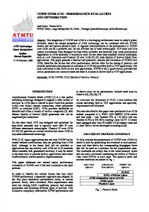
Fig. 1. ATM classical IP multicast configuration using point-to-multipoint PVC’s.
access point) within the switch. The procedure to configure a CIP multicast is described in detail as follows: 1) Configure an ATM interface (qaa0) for a standard “classical IP over ATM” with an appropriate ATMARP server address, operating over switched virtual circuit (SVC) connections. 2) Create a point-to-multipoint permanent virtual circuit (PVC) node (Multicast PVC) within an ATM switch using unique vpi/vci number for each multicast group, i.e., AWACS, Fighter, and UAV multicast groups. This Multicast PVC virtual node serves as a broadcast access point. 3) Create a virtual IP address for the Multicast PVC virtual node. Note that a unique IP subnet address should be assigned to each multicast group when multiple multicast group subnets are required. 4) Configure a new ATM interface (qaa1) for a CIP Multicast PVC virtual node at both the host and the client workstations with a proper virtual IP address. Repeat the process for the multiple subnets, as required. a) ifconfig qaa1 host station multicast IP address netmask 255.255.255.0 at a host station; b) ifconfig qaa1 multicast PVC virtual IP address netmask 255.255.255.0 at all client stations. 5) Bind IP addresses to the unique vpi/vci numbers at a host workstation and multiple client workstations, such as a) atmarp c multicast PVC virtual IP address qaa1 vpi vci revalidate at a host station b) atmarp c host station multicast IP address qaa1 vpi vci revalidate at all client stations 6) Make the final configuration (e.g., atmarp) persistent across reboots by writing a start-up script as necessary. 7) Run a standard “classical IP over ATM” on top of “Multicast PVC” virtual node connections. This permits the simultaneous transmission of point-to-point TCP unicast traffic over SVC, and point-to-multipoint UDP multicast traffic over multicast PVC. Fig. 1 shows the ATM CIP multicast configuration that allows for selectively broadcasting to the multiple battlespace groups.
(b)
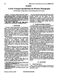
(c) Fig. 2. (a) FDDI TCP throughput. (b) ATM LAN emulation TCP throughput. (c) ATM classical IP TCP throughput.
III. NETWORK AND APPLICATION PERFORMANCE TEST The ATM LAN emulation was configured first and evaluated as a baseline reference point. The overall performance and scalability of the ATM LANE network is affected by its broadcast and unknown server (BUS). A multicast throughput required for advanced C I platform (a minimum 40-Mb/s multicasting data to multiple display consoles) also depends on the LANE BUS. Then, the BUS throughput was tested by measuring a broadcast forwarding rate over the ATM ELAN. For the worst-case MTU of 64 bytes, the BUS throughput of 60 Mb/s is considered to be the upper limit. Network Benchmark Test: The network benchmark tool, Netperf [4], was used for performance test and comparison among three network configurations; FDDI, ATM LANE, and ATM classical IP. The most common network benchmark test is to measure bulk data transfer performance (throughput) and transaction rate (latency) for a bidirectional TCP stream or a unidirectional UDP stream. The maximum throughput in TCP STREAM test of FDDI, ATM LANE, and ATM CIP was 96 Mb/s, 108 Mb/s, and 118 Mb/s, respectively, over a variable message size. The TCP STREAM throughput (Fig. 2) increased with the receive and transmit socket buffer size, but it was relatively insensitive to the message size when the message size was bigger than the maximum transmission unit (MTU).
KIM et al.: A MULTICAST CONFIGURATION WITH CLASSICAL IP OVER ATM
(a)
(b)
219
(a)
(b)
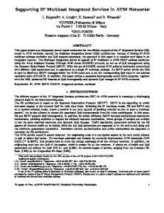
(c) (c) Fig. 3. (a) FDDI UDP throughput. (b) ATM LAN emulation UDP throughput. (c) ATM classical IP UDP throughput.
The UDP STREAM test showed that FDDI could handle UDP traffic better than the ATM LANE or classical IP, irrespective of a socket buffer size, as shown in Fig. 3. The UDP Request/Response (RR) transaction rate was tested (Fig. 4). A transaction is defined as the exchange of a single request and a single response. The round-trip average latency can be inferred from the transaction rate: with a 1kB message, 0.63 ms for FDDI, 0.58 ms for ATM LANE, and 0.60 ms for ATM CIP, all for TCP; and 0.61 ms in all cases for UDP. Then, the round-trip delay gets longer as the message size gets larger. The detailed tests will be described elsewhere [1], [2]. Application Benchmark Test: The application test was performed with AWACS mission computer and display console programs. The C I platform system loading can be a large number of simulated targets, sensor returns (e.g., radar or IFF returns), and active tracks. The maximum number of 3000 tracks and simulated targets were created and the sensor returns were then generated by the mission computer. While the information was continuously transmitted to the display consoles, the simultaneous TCP unicast and UDP multicast performance of the AWACS application was monitored over the variable track and socket buffer size. Test results showed that, below a buffer size of 32 kB, all networks had various
Fig. 4. (a) FDDI UDP RR transaction rate. (b) ATM LAN emulation UDP RR transaction rate. (c) ATM classical IP UDP RR transaction rate.
problems associated with a mission computer program and/or database transmit problems. Above 64 kB, the FDDI and ATM CIP showed normal operation, while ATM LANE showed mostly normal except an occasional panic problem; the display consoles running AWACS programs occasionally entered a panic mode and automatically rebooted. IV. SUMMARY The integrated battlespace simulation (IBS) was performed over ATM network. ATM multicast configuration with the multiple logical subnets of classical IP multicast-PVC’s and multiple emulated LAN’s, supporting the IBS network testbed with multiple platforms, was described. The network and application performance was then compared among three configurations of FDDI, ATM LAN emulation, and ATM classical IP multicast-PVC networks. REFERENCES [1] J. H. Kim, “Demonstration of ATM-based AWACS network with integrated battlespace simulation,” U.S. Air Force, Rome Lab., Final Tech. Rep., Oct. 1998. [2] J. H. Kim, N. P. Impert, J. M. DeFilipps, C. F. Derheim, M. Y. Thompson, S. Ray, and R. Butler, “ATM network-based integrated battlespace simulation with multiple UAV-AWACS-fighter platforms,” presented at the MILCOM’98, Bedford, MA, Oct. 18–21, 1998. [3] D. Ginsburg, ATM: Solutions for Enterprise Internetworking. Harlow, U.K.: Addison-Wesley, 1996. [4] “Netperf: A network performance benchmark (Revision 2.1),” HewlettPackard, Feb. 1996.