A Study on Inductive Power Transfer with Wireless
Tuning V. J. Brusamarello, Y. B. Blauth, R. Azambuja, I. Muller Electrical Engineering Department Universidade Federal do Rio Grande do SuI Porto Alegre, RS, Brazil email: {valner.brusamarello.yeddo.ivan.muller}@
[email protected]
Abstract
-
This paper presents the analysis of two loosely
coupled coils used to transfer energy to charge a battery. This battery is used to power an electronic device designed to monitor variables such as impact strength, range of temperature and humidity associated with the transport of fruits. The device is inside a sealed enclosure that cannot be opened for recharging the battery. The study shows the loosely coupled coils need to work with a resonance capacitor, at least on the secondary coil. However the resonance frequency also depends on the coupling factor k and the power delivered to the load. Therefore, this work proposes a monitoring system with closed loop for fine-tuning the resonance frequency of the secondary coil circuit. Before starting charging the battery the system scans the resonance frequency on the
primary coil
and
measures
the
output
power on
the
secondary coil looking for the optimal point. This procedure reduces problems of variation of coupling factor with positioning of the coils. Keywords - loosely coupled coils, resonance, battery charging, wireless.
I.
INTRODUCTION
Magnetically coupled coils have been widely used for a variety of applications requiring contactless or wireless power such as biomedical devices [1] -[2], instrumentation systems [3], among others [4]-[6]. In such applications, the energy transfer from the source to the load is done by loosely coupled coils, usually without a common magnetic core. These coils can be represented by the primary and secondary inductances Lj and L2, with a low coupling coefficient Kj2. In order to enhance the power transfer capability, the loosely coupled coils generally need to be compensated with capacitors to obtain the resonance effect [7]. Many works have shown that capacitive compensation is crucial to loosely coupled applications [1]-[7]. In addition to the power transfer capability, the operating efficiency of the coupled coils is of concern to many applications [7]. In fact, applications such as biomedical implanted devices [1] -[2] may require efficient power transfer in order to reduce time of charging associated to uncomfortable positions. In other applications the efficiency of the inductive link is required in order to avoid energy wasting, such as automotive battery charge devices [5]. The inductive power transfer system suffers severely from inefficient operation, particularly under light loading conditions [8]. Usually, in order to achieve the maximal power transfer efficiency some tuning technique is applied to the circuit. A
978-1-4577-1772-7/12/$26.00 ©2012 IEEE
typical approach for controlling the system uses variable frequency (VF) control in the resonant inverter to meet the zero phase angle (ZPA) [5] in the load impedance, and uses pulse width modulation (PWM) technique in the controlled rectifier of the output side to control the output voltage or current. According [2], [9], [!O] the power flow control of wireless power pickups is an important point that limit their further development. Load variations, magnetic coupling variations between the coils as well operating frequency drifting can cause the output voltage of the secondary power pickup to deviate significantly from the original designed value, resulting in undesirable characteristic for applications where a constant and stable output voltage is required [9] -[13]. Different methods have been proposed for controlling the load in loosely coupled coils such as the shorting control method [13] or the dynamic tuning/detuning technique proposed in [5], [14], [15]. The fundamental concept of the last technique is to dynamically change the tuning condition of the power pickup according to the actual load requirements. This feature increases the overall efficiency of the system and ensures that the quality factor of the designed circuit remains unchanged. Nowadays there is an increasing development of wireless devices, which need battery recharging regularly. Loosely coupled transformers have been proposed to work as charger to wireless devices such as mobile phones, where the primary core of the transformer is in the charger unit and the secondary core is in the telephone [4] or simply by applying a printed circuit-board [16]. In another application [l7], a detachable transformer is presented as a noncontact charging system for the batteries of an electrical shaver using a resonant converter. This paper describes the study of an inductive power transfer system for charging the batteries of an instrument that mimes a fruit such as an apple or an orange. Among other important variables the device records the mechanical shocks, using a 3-ring load cell during the post-harvest processing of apples and oranges [18], [19]. The small signals are acquired by a digital system and sent through a radio channel, which is linked to a similar system. In this work, the same wireless link is used to carry information about the secondary of two loosely coils built in order to charge the power supply batteries of the whole remote system. A converter was built in order to drive the primary coil and control the power delivered to secondary coil. The digital system in the fruit monitors the power in the batteries and sends the information to the base, which search
the tune frequency point, featuring a wireless loop control strategy. The following sections will show how important and sensible to small changes is the tune frequency to the maximum power delivered from the secondary coil to the load. In the presented work, the position of the secondary to the primary coil of the charger has a direct influence to the coupling factor and therefore has a direct impact on the detuning of the system. The feedback is used wirelessly, in order to tune the resonance and achieve the optimal working condition again. In a generic charging system, this strategy can be used to overcome the problem of dynamic loads, by scanning the secondary power, feed backing to the control system and adjusting the optimal operation point on the primary coil. II.
The total impedance from the primary coil is:
Z =ZRcfl +RLl + j(XL1-XM )+R, p
The current supplied by the power source (Fig. lc) is dependent of the total primary side impedance Z defined by p equation (4). Also, equation (4) shows that a series circuit resonant capacitor should have the impedance defined by
ZRC = img c{ZRefl} -j(XII -XM ) , where img _c{ZRcfl} is the imaginary parcel of the conjugate of the reflected impedance. The resonant capacitor on the primary coil can increase the drained power from the power source by decreasing the total series impedance, but the tune point will vary with the load. _
Mutual inductance [2 0] is defined by:
CIRCUIT ANALYSIS
M=
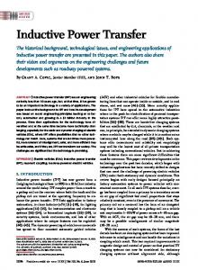
A. Analysis of the primary coil The equivalent circuit of two loosely coupled coils can be represented by three coils [20] (Fig. I a and Fig. I b). Considering the primary coil connected to the sinusoidal wave source and the secondary to a load, one can calculate the equivalent Thevenin of the circuit from the source side (Fig. I a). In this case the total impedance from the secondary coil is reflected to the primary side. By considering the load ZL = RL + jXL and the coil impedance ZL2 = RL2 + jXL2' the impedance on the secondary coil is: (I)
The
I xM (Rr +R,,)+i[CR, +R,,)2 +Cx, +X,,)2 -xMCx" +XrlJ
=XM l
reflected
CR, +R,,)' +CX, +X,,)'
impedance
ZRef with
the
primary
l
(3)
(5)
inductances coils. This reactance also depends on the coupling constant K, which change with the relative position of both coils. The variation of mutual inductance is reflected on the inductance of both sides, primary and secondary, and thus it also influences the resonance frequency of the circuit. B.
Analysis of the secondary coil
Considering the primary coil connected to the sinusoidal wave source and the secondary to a load, one can calculate the equivalent Thevenin of the circuit from the load side (Fig. 2).
E(ru)
.
K��L2
The reactance XM depends on primary and secondary
Thus the reflected impedance on the primary side is calculated by:
ZRef!
(4)
� (a)
Th
total
impedance Z[ defined by the source output impedance R" and the reactance and resistance of the inductor Zr] = Rr] + jXT.l determines the total current supplied by the voltage source.
(b) Figure 2. a) Two loosely coupled coils connected to a voltage source on the primary side and to a load on the secondary side; b) Equivalent Thevenin circuit from the secondary side.
The voltage reflected on the secondary coils (b)
defined by:
E\
(co)
is
(6) (e)
Figure 1. a) Two loosely coupled coils connected to a voltage source on the primary side and to a load on the secondary side; b) Equivalent circuit; c) Equivalent Thevenin circuit from the primary side.
Where
E
R[ = RLl +Rs'
(co) is
the
sinusoidal
voltage
source
and
And the equivalent impedance reflected on the secondary coils is:
load. If the load is resistive, the resonant capacitor value is a function of the circuit frequency, and the total inductance as shown in Figure 3. Variations in the capacitance or the inductance of this circuit can detune the resonance.
Where: R[ is the primary coil resistance summed to the source impedance;
XT.] is the primary reactance; XM is the mutual inductance defined by (8) Where L]
is the primary coil inductance,
secondary coil inductance and C.
K
L2 is the
the coupling constant.
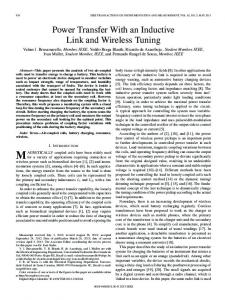
The total inductance of Figure 3 depends on the coupling factor K, which depends on the geometric position of both coils. Each time the coils are moved they will have a different coupling factor, resulting in a variable mutual inductance. Also, environmental factors such as humidity can change the capacitor value. Both situations require to fine-tune the resonance point of the circuit. The dependence of the resonance frequency of the circuit with the coupling factor can be seen in Figure 4. The values of the coupling factor K used in this work are based on measurements of a prototype coil, which will be presented in the next sections. D. Non linear load
Resonance effect on the secondary coil
The behavior of the circuit described in the previous sections become interesting if a capacitor is calculated in order to reach the resonance on the equivalent circuit representing the secondary side. Figure 3 shows the equivalent circuit of the impedance of the secondary coil in parallel to a current source. The current source Is (co) is the Norton current defined by:
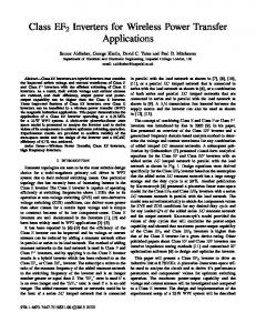
A rectifier block is necessary in order to have an application such as a battery charger. The diodes bridge connected to the battery features a non linear load. An interesting question to answer is how the circuit behaves with the nonlinear load. Inevenm VOltage as seen trom LL
'"
(9) The resistor Req represents the effect of the intrinsic resistance of the inductors and the resonant capacitor (which can be described by its quality factor Q), as well the output resistance of the input voltage source reflected to the secondary coil. This circuit shows that when the inductor and the capacitor reach the resonance, the current i2 is null. In that situation the current from the source is divided by the load (current ij) and the equivalent resistance Req (current i[). If the equivalent resistance Req is high enough then i[ is around zero and the current I, is supplied to the load. Equation (8) shows the dependence of the current source of the primary inductance L[, secondary inductance �, primary coils resistance R[, secondary resistance R2, and the coupling constant
K.
Is -
20 ""
Figure 4.
100000 f
Dependence of the resonance frequency with the coupling constant K .
The response is especially important if we are interested in optimizing the energy transfer to the load. The analysis of the circuit was done by using a simulator based on spice. In this simulation, the load is a resistor which assumes different values. The capacitor C is calculated in order to the secondary coil reaches the resonance. The results of the simulations are summarized on table I (K = 0.29 , RLl = IQ , RL2 = 0.9Q , � = 77�H, L2 = 48�H, C=23InF , CR = 1O�F, e(t) is a AC pulse source ranging from -15 to +15 V, 50000 kHz).
Figure 3.
Equivalent source supplying the current to the load on the resonance.
In order to reach the resonance on the secondary coil a capacitor should be calculated and connected in parallel to the
Figure 5.
Simulated circuit used to analyze the non linear load.
TABLE 1.
POWER ON THE LOAD BASED ON SIMULATED VALUES
Zr
Load Current
Load Power
10
175 rn A
30 mW
100
160 mA
256 mW
500
144 mA
1.03 W
1000
123 rn A
1.03 W
2000
100 mA
2W
2700
90 mA
2.2 W
5000
67 rn A
2.2 W
10000
42 mA
1,7 W
50000
1l.5 rn A
0.6 W
Table 1 shows that the maximum power transfer, for this case in particular, occurs when the load takes a value between 270 and 500 ohms. In the case of the battery charger, this indicates that there is an optimal point at which the voltage converter to power the battery must be designed. It is important to note that the maximum power transfer depend on the load (Figure 6) and the coupling factor (Figure 7).
III.
METHODOLOGY AND RESULTS
The main objective of this paper is to study and develop a wireless charger to be used in an electronic device designed to monitor variables associated with the transport of fruit and the like. The results of the first prototype, as well as details of construction of the instrument for wireless monitoring of variables was presented in [18]. The first variables to consider are the size and geometry of the enclosure in which the electronic device is packed. Due to the spherical geometry and simplicity we chose to develop two solenoid coils. One with a diameter slightly larger than the diameter of the sphere to work as a primary coil which should be at the power charger. The secondary coil should be located inside the sphere, which is sealed. Figure 8 illustrates the sphere used in the prototype. the relative position between the two coils is crucial to define the coupling factor K. A slight misalignment between the coils causes the variation in the coupling factor and consequently the resonance frequency, as shown in Section 2. Finally, the loss of tune considerably decreases the ability to transfer energy to the load.
Seoondary Output Power (k:O.74)
Figure 8.
Spherical geometry of the developed prototype.
A. Drive to the primary coil Figure 6.
Dependence of power transferred to the load on the output. Secondary Output Power (ZL=50)
lOOcm f
Figure 7. factor K.
Dependence of power transferred to the variation of coupling
The primary coil uses a four-quadrant inverter so that the current oscillates between positive and negative values (average current in the load is zero). The inverter applies a square wave from -15 to + 15 V with a frequency of 50 kHz. It is important to notice that, since we use a resonant circuit, the waveform of the input rectifier is sinusoidal because the high frequency components are filtered. The power delivered by the source depends on the total impedance seen in the primary winding. Since this impedance has an inductive component, one can use a capacitor in series to force the resonance, resulting in considerable increase of current in the primary coil and consequently the energy transfer to the secondary coil. The choice of the capacitor to be placed in series depends on the capacity of the power source and must be done carefully. Figure 9 illustrates the drive circuit used in this work.
resonance frequency is very sensitive to the varIatIOn of the coupling factor K. It is inevitable that the relative position between the coils of the charger varies in each battery recharge, varying the inductance reflected to the secondary. Thus, this paper proposes an adaptive control for fine-tuning the resonance frequency of the secondary coil circuit, using a wireless communication link between the control system.
Bl Control system
Figure 9. B.
Dependence of power transferred to the load on the output.
Power on the load
The circuit shown in Figure 5 was used to test two different conditions and measure the total power delivered to the load:
Concerning platforms that include MCV and radio in the same chip, there are several options, among them, the Freescale's MC1322X. This platform includes an ARM 7 MCV and an IEEE 802.15.4 radio, besides standard peripherals such as a 12 bit ADC with multiple inputs. Since such platform has been used in the development of the measuring device, it is very suitable for the application of the battery charger. Thus, the MCV in the measuring device monitors the battery and communicates with the MCV that controls and adjusts the frequency in the charger base, working in the primary coil (Figure 10).
a. In the first situation the secondary coil was placed inside the primary coil in order to have a strong coupling (K '" 0. 7 ). b. In the second situation the secondary coil was placed outside the primary coil in order to have a weak coupling (K '" 0.3 ) .
Secondary
I n both situations the load Z L was a set o f resistors. The output voltage was measured and the power calculated. The results are shown in Table 2. TABLE II.
ZL (0.)
POWER ON THE LOAD BASED ON RESISTNE LOAD
Voltagel
Load Powerl
VOltage2
Load Powe?
6. 8
1.9
0. 3
0.5
0. 01
47
12
1.6
3.0
0.05
100
24
2.6
5.7
0.06
270
44
4. 8
7.1
0.08
470
57
6
6.9
0.08
1000
63
7
3.9
0.04
4700
74
8
1.1
0.01
OC
75
10
--------------
----------
l 2
strong coupling
Figure 10. Block diagram of the charger.
Concerning the software, the MCV of the primary coil initializes the communication link with the MCV of the secondary coil. Thus, the control system on the primary side starts a scan frequency synchronized with the measures of power in the load carried by the control system on the secondary side. At each frequency point a measure of power is performed on the secondary side. This measure is sent by the wireless link to the primary and compared with the previous measure. The algorithm searches for the optimum point and adopts it as the resonance frequency and starts charging the battery. Figure 11 illustrates the described wireless loop.
weak coupling
OC - open circuit The practical results shown in Table 2 confirm the simulated results shown in Table 1. The maximum power transfer occurs when the load is between 100 and 470 o.. Thus the intrinsic resistances of the inductors and the capacitor, as well as the internal resistance of the AC source used in the simulation have realistic values. C.
Wireless tuning
Figures 4, 6 and 7 show that the load voltage and power are very sensitive to frequency variations. Figure 4 shows that the
Figure 11. Block diagram of the charger with wireless communication.
IV.
CONCLUSIONS
This paper presents the analysis of two loosely coupled coils used for charging an electronic device that monitors variables associated with the transport of fruits. Once the measuring device is sealed, the charging cannot be made with wires connecting the power source and the battery. The primary coil is connected to a PWM inverter controlled by an MCU, which among other features has a wireless communication module. The secondary coil is connected to the battery charging circuit in which current and voltage are monitored. This monitoring is made by another MCU that controls the measuring device and communicates with a remote base. The coils analysis showed that the circuit needs at least one capacitor to force the resonance in the secondary coil in order to optimize the energy transfer between the coils. However, the impedance reflected to the secondary side depends on the coupling factor K and thus the resonance frequency. Also, the positioning between the two coils causes a variation of the coupling factor K in the battery recharge. Thus, this paper proposes a closed loop system to monitor the power delivered from a charger circuit during the battery charging process. The MCU that monitors the loader circuit in the device communicates with the MCU that controls the primary coil driver when the charging process starts. The MCU in the AC power base starts a frequency scanning step by step. The algorithm searches for the frequency where the maximal power is delivered to the charging battery. This point is assumed to be the resonance frequency, thus the battery charge process continues until the full charge is reached. REFERENCES [I]
P. Li and R. Bashirullah, "A wireless power interface for rechargeable battery operated medical implants," IEEE Trans. Circuits Syst. II, Exp. Briefs,vol. 54,no. 10,pp. 912-916,Oct. 2007.
[2]
R.R. Harrison, "Designing efficient inductive power links for implantable devices," In: Proc. 2007 IEEE Inti. Symposium on Circuits and Systems (ISCAS 2007),New Orleans,LA,pp. 2080-2083, 2007.
[3]
J. de Boeij, E. Lomonova, J. L. Duarte, and A. J. A. Vandenput, "Contactless power supply for moving sensors and actuators in highprecision mechatronic systems with long-stroke power transfer capability in x-y plane," Sens. Actuators A, Phys., vol. 148, no. I, pp. 319-328,Nov. 2008.
[4]
Chang-Gyun Kim, Dong-Hyun Seo, Jung-Sik You, Jong-Hu Park, and Bo H. Cho, "Design of a Contactless Battery Charger for Cellular Phone", IEEE Transactions on Industrial Electronics, Vol. 48, N. 6, pp. 1238-1247,2001.
[5]
c.-S. Wang, O. H. Stielau, and G. A. Covic, "Design considerations for a contactless electric vehicle battery charger," IEEE Trans. Ind. Electron., vol. 52,no. 5,pp. 1308-1314,Oct. 2005.
[6]
T. Bieler, M. Perrottet, V. Nguyen, and Y. Perriard, "ContactIess power and information transmission," in Conf. Rec. IEEE-lAS Annu. Meeting, vol. 1,2001,pp. 83-88.
[7]
Chih-Jung Chen, Tah-Hsiung Chu, Chih-Lung Lin, and Zeui-Chown Jou, "A Study of Loosely Coupled Coils for Wireless Power Transfer" IEEE Transactions on Circuits and Systems - IT: Express Briefs,Vol. 57, N. 7,pp. 536-540,2010.
[8]
S. Hussmann and A. P. Hu, "A microcomputer controlled ICPT power pick-up and its EMC considerations for moving sensor applications," in Proc. Int. Conf. Power Syst. Technol.,Oct. 13-17,2002,pp. 1011-1015.
[9]
Jr-Uei William Hsu,Aiguo Patrick Hu,and Akshya Swain, "A Wireless Power Pickup Based on Directional Tuning Control of Magnetic Amplifier", IEEE Transactions on Industrial Electronics, Vol. 56, N. 7, pp 2771- 2781,2009.
[10]
Jr-Uei W. Hsu, Aiguo P. Hu, Akshya Swain, "Fuzzy based Directional Tuning Controller for a Wireless Power Pick-up", TENCON 2008 2008 IEEE Region 10 Conference,19-21 Nov. 2008.
[II]
Y.-H. Chao, J.-J. Shieh, C.-T. Pan, W.-c. Shen, and M.-P. Chen, "A primary-side control strategy for series-parallel loosely coupled inductive power transfer systems," in Proc. 2nd ICIEA,May 23-25, 2007,pp. 2322-2327.
[12]
G. A. Covic, J. T. Boys, M. L. G. Kissin, and H. G. Lu, "A three-phase inductive power transfer system for roadway-powered vehicles," IEEE Trans. Ind. Electron.,vol. 54,no. 6,pp. 3370-3378,Dec. 2007.
[13]
C.-S. Wang, O. H. Stielau, and G. A. Covic, "Load models and their application in the design of loosely coupled inductive power transfer systems," in Proc. Int. Conf. Power Syst. Technol., PowerCon,Dec. 4--7, 2000,pp. l053-1058.
[14]
J. James,J. T. Boys,and G. A. Covic,"A variable inductor based tuning method for ICPT pickups," in Proc. 7th IPEC, Nov. 29-Dec. 2, 2005, pp. 1142-1146.
[IS]
P. Si, A. P. Hu, S. Malpas, and D. Budgett, "Switching frequency analysis of dynamically detuned ICPT power pick-ups," in Proc. Int. Conf. Power Syst. Technol., PowerCon,Oct. 2006,pp. 1-8.
[16] Xiao Zhi Jian; Han Zhen Yu; Sichuan Univ., Chengdu, "A novel wireless charging system for movable telephone with printed-circuit board windings of different structure and shape respectively", ICEMS. International Conference on Electrical Machines and Systems, 2007, pp. 1283 - 1285. [17] Abe, H. Sakamoto, H. Harada, K. Home Appliances R&D Centre, Matsushita Electr. Works Ltd., Osaka, "A noncontact charger using a resonant converter with parallel capacitor of the secondary coil", IEEE Transactions on Industry Applications,MarlApr 2000,pp. 444 - 451. [18]
Muller I., Brito R. M., Pereira C. E., Brusamarello V., "Load Cells in Force Sensing Analysis - Theory and a Novel Application", IEEE Instrumentation & Measurement Magazine,February 2010,pp. 15-19.
[19]
Muller I., Brito R. M., Bender R. J., "Instrumented Sphere for Compression Analysis ",in Proc. IEEE ITMTC 2008, 2008.
[20] James W. Nilsson, Susan A. Riedel, Electric Circuits, Ed. 8, Prentice Hall, 2007.