314
IEEE TRANSACTIONS ON RELIABILITY, VOL. 61, NO. 2, JUNE 2012
A Technical Framework and Roadmap of Embedded Diagnostics and Prognostics for Complex Mechanical Systems in Prognostics and Health Management Systems Z. S Chen, Y. M Yang, and Zheng Hu
Abstract—Prognostics and Health Management (PHM) technologies have emerged as a key enabler to provide early indications of system faults and perform predictive maintenance actions. Implementation of a PHM system depends on accurately acquiring in real time the present and estimated future health states of a system. For electronic systems, built-in-test (BIT) makes it not difficult to achieve these goals. However, reliable prognostics capability is still a bottle-neck problem for mechanical systems due to a lack of proper on-line sensors. Recent advancements in sensors and micro- electronics technologies have brought about a novel way out for complex mechanical systems, which is called embedded diagnostics and prognostics (ED/EP). ED/EP can provide real-time present condition information and future health states by integrating micro-sensors into mechanical structures when designing and manufacturing, so ED/EP has a revolutionary progress compared to traditional mechanical fault diagnostic and prognostic ways. But how to study ED/EP for complex mechanical systems has not been focused so far. This paper explores the challenges and needs of efforts to implement ED/EP technologies. In particular, this paper presents a technical framework and roadmap of ED/EP for complex mechanical systems. The framework is based on the methodology of system integration and parallel design, which includes six key elements (embedded sensors, embedded sensing design, embedded sensors placement, embedded signals transmission, ED/EP algorithms, and embedded self-power). Relationships among these key elements are outlined, and they should be considered simultaneously when designing a complex mechanical system. Technical challenges of each key element are emphasized, and the corresponding existed or potential solutions are summarized in detail. Then a suggested roadmap of ED/EP for complex mechanical systems is brought forward according to potential advancements in related areas, which can be divided into three different stages: embedded diagnostics, embedded prognostics, and system integration. In the end, the presented framework is exemplified with a gearbox.
Index Terms—Complex mechanical systems, embedded diagnostics and prognostics, prognostics and health management.
Manuscript received October 15, 2011; revised December 26, 2011; accepted January 20, 2012. Date of publication May 17, 2012; date of current version May 28, 2012. This work was supported by the National Natural Science Foundation of China under Grant 50805142. Guest Associate Editor: Q. Miao. The authors are with the Key Laboratory of Science and Technology on ILS, College of Mechatronics Engineering and Automation, National University of Defense Technology, Changsha 410073, China (e-mail: czs_study@ sina.com;
[email protected];
[email protected]). Color versions of one or more of the figures in this paper are available online at http://ieeexplore.ieee.org. Digital Object Identifier 10.1109/TR.2012.2196171
ACRONYMS ED/EP
embedded diagnostics and prognostics
PHM
prognostics and health management
CBM
condition based maintenance
RUL
remaining useful life
BIT
built-in-test
SNR
signal-to-noise ratio
QSDG
quantitative signed directed graph
EH
energy harvesting I. INTRODUCTION
P
ROGNOSTICS AND HEALTH MANAGEMENT (PHM) comes from the U.S. Department of Energy and the U.S. Department of Defense (DoD). The motivation is to reduce the operation and support (O&S) costs of large military or industrial systems while maintaining or increasing the availability of these systems. According to [1]–[5], PHM is an approach to system life-cycle support that seeks to reduce or eliminate inspections and time-based maintenance through accurate monitoring, incipient fault detection, and prediction of impending faults. So PHM technologies have emerged as a key enabler to provide early indications of system faults, and perform predictive maintenance actions. The capability allows end users to perform better planned maintenance, reduce or eliminate unnecessary inspections, and decrease time-based maintenance intervals with confidence. When coupled with autonomic logistics, PHM can improve mission-critical system reliability & availability, and reduce logistics delay time, on-demand repair actions and sparing, and life-cycle costs [2], [6]–[8]. By now, many studies have been done for PHM as a means of providing advanced warnings of failure, and enabling conditionbased maintenance. DARPA is interested in developing “selfaware” systems [9]. The Applied Research Laboratory at Pennsylvania State University has been working in the area of condition-based maintenance and machinery health monitoring for many years. They have developed many tools and approaches relating to PHM [10]. The Society for Machinery Failure Prevention Technology (MFPT) holds an annual meeting on PHM each year. Prof. Michael G. Pecht at the University of Maryland
0018-9529/$31.00 © 2012 IEEE
CHEN et al.: FRAMEWORK AND ROADMAP OF ED/EP FOR COMPLEX MECHANICAL SYSTEMS IN PHM SYSTEMS
has conducted many valuable studies on PHM [11]–[13], and proposed a PHM roadmap for information and electronics-rich systems [13]. Impact Technologies, Inc. has developed engineering tools and generic customized software modules for mechanical component diagnostics and prognostics over a broad range of applications [14]. These software modules can be tailored for both critical, high fidelity applications such as military aircraft subsystems, and lower cost, higher volume industrial applications. The Machinery Information Management Open Systems Alliance (MIMOSA) has adopted the development and support of the Open System Architecture Condition Based Maintenance (OSA-CBM) standard that purports to provide a standard architecture for PHM systems [15]. Based on the OSA-CBM structure, a PHM system can be divided into several layers: sensors & data acquisition, condition monitoring, fault diagnostics, predicting remaining useful life (RUL), and health management. The PHM system generally combines sensing and interpretation of environmental, operational, and performance-related parameters to assess the health of a product, and predict its remaining useful life. Thus, in PHM systems, it is the most important to obtain real-time condition information of a given subsystem accurately, which is the basis of fault detection, and predicting its future health status. PHM relies on long-term accurate in situ information. For electronic systems, built-in-test (BIT) makes it easy to achieve these goals [16], [17]. BIT can incorporate test and diagnostic functions into an electronic component at the design stage. Such a design philosophy has been widely applied to the design and testing of complex electronic systems, such as integrated circuits. On the other hand, mechanical systems play increasingly important roles in industry, aeronautics, military areas, and so on. Furthermore, mechanical systems are significantly contributed to both safety incidents and maintenance costs. So it is necessary to perform fault prognostics and health management of complex mechanical subsystems for preventing major breakdowns due to progression of undetected faults. Unlike electronic systems, the condition of a complex mechanical system is always characterized by physical signals which are stochastic and prone to be contaminated by surrounding noises, such as vibration [18], [19], temperature [20], and so on. Also, there are frequently no testing points reserved on key components in mechanical systems at the design stage. We can only mount sensors outside, so it is very difficult to acquire ‘true’ condition signals of these components. Consequently, there is a pressing need to apply BIT philosophy into complex mechanical systems for PHM. Recent advancements in sensors and micro-electronics technologies have brought about a novel way of BIT applications for complex mechanical subsystems, which is called Embedded Diagnostics and Prognostics (ED/EP) [21], [22]. Over the past decade, ED/EP has been considered to be a key component of PHM systems. Research in the ED/EP of mechanical systems or structures is a means of providing on-line condition information, and enabling condition-based maintenance. R.X. Gao embedded a wireless sensor module into a small slot milled on the outer raceway of a ball bearing to provide “on-thespot” fault detection capability [23]. Acellent , Inc. has developed a patented SMART Layer technology for health monitoring of structures, which is a thin dielectric film with an embedded piezoelectric sensor network that can be embedded
315
inside composite structures [24]. Impact Technologies, Inc. provides a capability to deploy the most advanced embedded health monitors using a variety of methods from stochastic processes to state space models and artificial intelligence [25]. TEAMS-RT of Qualtech Systems, Inc. is a fast, compact reasoner running on a vehicle’s on-board computer to provide real-time diagnostics and system health monitoring. It uses a subset of the TEAMS model of the vehicle or machine, and processes the results of on-board, built-in tests to perform diagnostics [26]. However, to our knowledge, there are no systematic guidelines for studies on the ED/EP of mechanical systems. The goal of this paper is to present a technical framework of ED/EP for complex mechanical systems, and underlying opportunities & challenges. Then a roadmap of ED/EP is suggested to show its future trends. In the end, we present an example to demonstrate the implementation of ED/EP. II. DEFINITION OF ED/EP, AND ITS NEEDS FOR COMPLEX MECHANICAL SYSTEMS A. Roles of ED/EP in PHM Systems The importance of PHM has been explicitly stated in the U.S. Department of Defense (DoD) 5000.2 policy document on defense acquisition. A definition of PHM proposed by Sandia National Laboratories (SNL) is as ‘the capability to estimate the likelihood of a system failure over some future time interval so that appropriate actions can be taken’ [27]. In general, a PHM system consists of several features: • Raw Data — On-line, off-line sensor data — Historical maintenance/failure data — Model data • Diagnostics — Data pre-processing — Data interpretation — Data fusion — Determining fault types and severities • Prognostics — Estimation of system “health” index — Predictions of RULs • Health Management — What should be done? — How to do it? — When should it be done? Also SNL has proposed a PHM system structure as Fig. 1 [27]. The Evidence Engine aims for feature extraction, trend detection, information fusion, and estimation of remaining useful life. And the Consequence Engine aims to analyse the consequences of various maintenance actions. It can be seen from the PHM structure that sensor subsystems are the basis of PHM. In particular, PHM systems give rise to special needs on sensor subsystems with multiple sensing abilities, miniature size and light weight, low power consumption, long range and high rate data transmission, large onboard memory, fast onboard data processing, low cost, and high reliability [28]. The typical structure of sensor modules for PHM is shown in Fig. 2. It can be seen that onboard sensing and processing
316
IEEE TRANSACTIONS ON RELIABILITY, VOL. 61, NO. 2, JUNE 2012
Fig. 1. The PHM system structure [27].
Fig. 3. Comparison between (a) traditional methods and (b) ED/EP.
Fig. 2. Typical structure of sensor modules for PHM systems.
functions are integrated into the sensor modules. In traditional sensing strategies, we often need to mount sensors on structures, and then collect the signals by one acquisition card, so that miniature size and low power consumption cannot be achieved. The U.S. DoD points out that the manager in PHM systems can optimize operational readiness through affordable, integrated ED/EP, embedded training and testing, serialized item management, automatic identification technology, and iterative technology refreshment [29]. So ED/EP has been considered to be a key enabler to PHM. There have been no standard definitions for ED/EP in the literature. In this paper, we define ED/EP as ‘analyzing data from embedded sensors or test equipment to continuously assess the operational status of a device, and predict its future state. When the performance or predicted remaining lifetime reaches a specified threshold, it will issue an alert, and submit a requisition for maintenance’. B. ED/EP of Complex Mechanical Systems During the life cycle of a complex mechanical system, the design stage is often separated from its usage stage. That is to say, the designers rarely consider how to reserve testing points and perform health monitoring. Thus in practice it is necessary to mount additional sensors to perform condition monitoring, fault diagnostics, and prognostics. For example, vibration analysis is the most popular way of condition monitoring and fault detection for complex mechanical systems. By observing the changes in the vibration spectra over time, a skilled engineering can interpret its condition, and more importantly give prior warning
of imminent failure. This warning facilitates a planned maintenance and repair program, and avoids costly down-time. A traditional fault diagnostic and prognostic scheme of mechanical systems is shown in Fig. 3(a). In practice, however, it is very difficult to achieve accurate fault diagnostics and prognostics using traditional methods for complex mechanical systems such as helicopter gearboxes, and aero engines. The reasons may include the following. • Sensors may not access a faulty component directly due to many limitations. Because there are no reserved testing points at the design stage, we can only mount sensors on mechanical components or structures to sample signals. However, in many cases, we cannot easily mount a sensor on a faulty component directly, such as bearings or gears in a helicopter gearbox, shafts in an engine, and so on. In particular, it may not be allowed to mount sensors on compact or moving structures in mechanical systems. • Low signal-to-noise ratio (SNR) due to surrounding interferes. For vibration analysis, the monitored mechanical component cannot be sensed directly in many cases, so vibration signals from sensors are always not the ‘true’ condition signal, but mixed with signals from other components and environment noise. Thus SNRs of useful condition signals are low. • Difficult to extract accurate fault features. Because mechanical systems are often complex and work under variable loads, its dynamic behaviors are also complex due to strong coupling among different components. Thus it is difficult to extract accurate fault features by traditional ways. • Poor prognostic ability. There are often no on-line sensors on key components in mechanical systems, and we cannot obtain continuous condition signals, so the ability of fault prognostics is very poor. Up to now, real-time and accurate signal acquisition has been a bottle-neck problem for complex mechanical systems. To solve this problem, the concept of ED/EP has been proposed by the U.S. Army. The basic scheme of ED/EP is shown in
CHEN et al.: FRAMEWORK AND ROADMAP OF ED/EP FOR COMPLEX MECHANICAL SYSTEMS IN PHM SYSTEMS
Fig. 4. A technical framework of ED/EP for complex mechanical systems.
Fig. 3(b), where the capability of fault diagnostics and prognostics is considered in parallel at the design stage. The features of ED/EP of complex mechanical systems are numerous: • Bit-in-Test (BIT) and prognostic functions for CBM/PHM systems are possible. • Micro-sensors integrated into mechanical components or structures at the design stage, which makes mechanical systems self-sensing, self-diagnostic and prognostic, and self-reporting. • Near-real-time fault diagnostics and prognostics ability with less human interaction. • Smart, autonomous mechanical systems are possible. III. A TECHNICAL FRAMEWORK OF ED/EP FOR COMPLEX MECHANICAL SYSTEMS Developing the infrastructure to implement an ED/EP system is still a major challenge, and underlying key technologies have to be outlined. In this section, a technical framework of ED/EP for complex mechanical systems is proposed in Fig. 4, which includes six key elements: embedded sensor modules, embedded sensing design, optimal placement of embedded sensors, embedded signal transmission, ED/EP algorithms, and embedded self-power. The arrows denote the restriction relationships among these elements, which can be summarized as follows. • When designing embedded sensor modules, we must consider the feasibility of signal transmission under embedded working conditions, implementation of ED/EP algorithms under the limited calculation sources of micro-processors, space limitations in complex mechanical systems, and power consumption limitations for long lifetimes. • When performing embedded sensing design, we must consider the restrictions of the size of each embedded sensor module, and allowable spaces in complex mechanical systems. • When performing embedded sensors’ optimal placement, we must consider the restrictions of the size of each embedded sensor module, allowable spaces, costs, and the ability of diagnostics and prognostics. Also, there are two important integration procedures in Fig. 4. The first one is the integration of embedded miniature sensor modules by itself, which includes the sensing element, signal
317
transmission element, self-powering element, and signal processing algorithms. The other is the integration between embedded miniature sensor modules and mechanical components or structures. The main challenges of ED/EP that we face are numerous. • What kind of key condition parameters must be monitored? • What kind of sensor modules should be used? • Miniature, robust, reliable sensor modules are needed for embedding. • Where should sensor modules be embedded? • How do we embed sensor modules to reduce their effects on the structure integrity? • How do we embed the minimum number of sensors to cover the maximum number of faults, i.e., optimal placement? • What are the costs and benefits associated with embedding sensor modules? • Reliable signal transmission is necessary. • The calculation abilities and storage space of microprocessors are limited. • Embedded sensor modules must be self powered. A. Embedded Sensor Modules for Mechanical Systems ED/EP relies highly on the sensor systems to obtain long-term, accurate, in situ information to provide anomaly detection, fault isolation, and rapid failure prediction. Embedded sensor modules are the essential devices used to monitor parameters for ED/EP of mechanical systems, such as temperature, vibration, shock, pressure, acoustic levels, strain, stress, and so on. Considerations of embedded sensor modules’ design for ED/EP may include the parameters to be measured, the performance needs, multiple sensing abilities, miniature size and light weight, low power consumption, large onboard memory, fast onboard data processing, low cost, and high reliability. A generic embedded sensor module will typically have sensing elements, onboard analog-to-digital converters, onboard memory, embedded computational capabilities, data transmission, and a power source or supply [22]. In recent years, significant growth in the field of adaptive structures has achieved advancement in sensor material that can perform embedded measurement. Chief among these are piezoelectric, magnetstrictive, and optical materials. By now, the promising embedded sensors mainly include acoustic wave sensors, electromagnetic sensors, optical sensors, Micro-Electro-Mechanical Systems (MEMS) sensors, and thin film sensors [30]. B. Embedded Signal Transmission for Mechanical Systems For the ED/EP of complex mechanical systems, reliable signal transmission is a challenge. Traditional hard wiring methods will face many problems because wiring may not be permitted in some extreme environments, or many embedded sensors will push the weight and cost of wiring to significant levels. There are two main embedded signal transmission methods for complex mechanical systems: optical fiber communication, and wireless communication [30]. Optical communication has been researched extensively over the past ten years for different applications, which has the potential for implementing multiple sensors on a single fiber. For example, optical sensors can be embedded into the composite structures
318
of aircrafts to transmit strain, and temperature signals. Wireless communication has advanced significantly in commercial practice, and the emphasis is on high channel bandwidth and low power for ED/EP. There are several mature wireless communication protocols, such as 802.11b, Bluetooth, RF, and so on. Because many mechanical systems are made of metal material, electromagnetic interferences have unavoidable impacts on the performance of wireless communication. This matter must be addressed to permit reliable wireless signal transmission as the RF environment becomes increasingly crowded in complex mechanical systems. Utilization of coding schemes, frequency management, management of transmitted power, and directional antennas may factor into controlling and adapting to changing RF conditions. Future research will focus on ultra-width band, long range, and high rate data transmission. C. Embedded Sensing Design for Mechanical Systems The implementation of such an ED/EP mechanism needs to embed miniature sensor modules into mechanical components or structures, such as a bearing or a gear. However, how to embed the miniature sensor modules into mechanical systems is a challenging task because it indeed will affect the structural integrity. To ensure consistent structural integrity after embedding, it is necessary to perform embedded sensing design. There are two important steps. First, dynamic analysis of a modified mechanical component or structure needs to be done to evaluate the impact of embedded sensors on the structure integrity. In general, we can compare natural frequencies and modal shapes. Second, a finite element-based method is used for modeling and analysis of the modified mechanical component or structure to testify the feasibility of embedded sensing design. D. Embedded Sensors Optimal Placement for Mechanical Systems For complex mechanical systems, embedding a single sensor is not enough for accurate fault diagnostics and prognostics. Obviously, a multi-sensor system can overcome the limitations of a single sensor system, and has better performance. At the same time, to avoid destructing the structural integrity, we often prefer the number of sensors to be as small as possible. So we need to perform embedded sensors optimal placement. The goal is to obtain the maximum fault coverage with the minimum number of embedded sensors. We can build an optimal model of embedded sensors placement by quantifying fault sensitivities of all embedded sensors. For example, in vibration analysis, the fault sensitivity of each embedded sensor is tightly related to transmission paths between its location and fault source. So vibration propagation information can be used for embedded sensors optimal placement. A signed directed graph (SDG) method can provide a simple graphical representation of a complex system, and depict cause-effect relations of fault vibration propagation [31]. Thus we can use a SDG of fault vibration propagation to build an optimal model of embedded sensors placement. The corresponding optimal algorithms include genetic algorithm (GA) [32], particle swarm optimization (PSO) algorithm [33], and so on.
IEEE TRANSACTIONS ON RELIABILITY, VOL. 61, NO. 2, JUNE 2012
E. ED/EP Algorithms for Mechanical Systems The core of ED/EP is a microprocessor, so its calculation and storage ability are limited. Many advanced signal processing or reasoning algorithms cannot be used here. To solve this problem, a model-based algorithm may be a proper alternative [34], such as AR, ARMA, neural network, and so on. F. Self Power for ED/EP for Mechanical Systems It is a major challenge to provide power for ED/EP systems. Traditionally, batteries are often used for wireless sensors. However, the lifetime of a battery is always limited, so it must be replaced periodically. When there are many embedded sensor modules, replacement of depleted batteries becomes time consuming and significantly wasteful. In particular, it may not be prudent to replace the battery in some extreme conditions. As a result, there is a clear need to explore novel alternatives to power embedded sensor modules. Harvesting energy from their local environment has become a novel power source for wireless sensors with potentially lower cost and weight, such as vibration [35], RF [36], thermal [37], and solar [38]. An embedded sensor module will benefit from an extended life and from being self powered. Self power for embedded sensor modules can be split into two main technology categories: reducing the power consumption, and increasing the efficiency of energy harvesting. IV. A SUGGESTED ROADMAP OF ED/EP MECHANICAL SYSTEMS
FOR
COMPLEX
The ED/EP of complex mechanical systems is far from maturity due to many technical challenges. However, potential advancements in related areas will impel its development in the future, such as MEMS, advanced micro- electronics, smart materials and structures, advanced manufacturing, and so on. In this section, we suggest a roadmap of ED/EP for complex mechanical systems shown in Table I, which can be divided into three developing stages: 1) Embedded diagnostic stage: In this stage, we need to focus on advanced embedded sensors under extreme conditions, on-line signal processing methods, on-line fault diagnostics and isolation algorithms, and reliable embedded signal transmission technologies. By now, this stage has almost been accomplished by the U.S. Army. 2) Embedded prognostic stage: In this stage, we need to focus on reliable self-powered technologies, physics-of-failure (PoF) models-based fault prognostic methods, the fusion of data-driven and PoF-based prognostic algorithms, and developing and testing the prototype of ED/EP for complex mechanical systems. 3) Integration stage: In this stage, the integration of ED/EP in mechanical systems is achieved. Complex mechanical systems will be truly smart and autonomous, with the ability of self-sensing, self-diagnostic and prognostic, self-report, even self-healing. So that the ED/EP of complex mechanical systems can be seamlessly connected to health management information systems. V. A CASE STUDY: ED/EP OF A GEARBOX To demonstrate the feasibility of the proposed ED/EP structure, a testing case is shown here. As we all know, gearboxes are one kind of important rotating machinery, and widely used
CHEN et al.: FRAMEWORK AND ROADMAP OF ED/EP FOR COMPLEX MECHANICAL SYSTEMS IN PHM SYSTEMS
319
TABLE I A SUGGESTED ROADMAP OF ED/EP
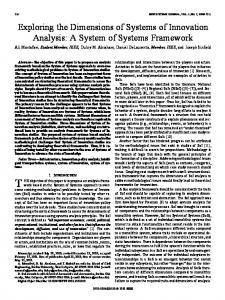
Fig. 6. (a) Modified bearing and (b) its percentage increase in radial deflection.
Fig. 7. (a) Schematic diagraph of a modified gear and (b) its finite element model.
Fig. 5. (a) A two-stage gearbox and (b) its internal view.
in military and industrial equipment. Therefore, the ED/EP of gearboxes is necessary to prevent major breakdowns, and improve their operational capability. In this section, we choose a two-stage gearbox (shown in Fig. 5) as an object to show the implementation of the technical framework in Fig. 4. Here, on-line vibration signal analysis is used. The selected gearbox includes six bearings and four gears as shown in Fig. 5(b). A. Embedded Sensing Design Bearing and gears are two kinds of key components in a gearbox, which have different faults due to their work conditions. We can decide to embed miniature sensor modules into bearings and gears at the design stage. For bearings, a slot can be cut from the outer race to hold the sensor module, as in Fig. 6(a). At the same time, the slot must be kept small enough to avoid causing the outer race to fail. Cutting a slot will cause an increase in both stress and deflection, and deflection is the key limiting factor for its structural integrity [39]. Then a finite element-based simulation can be done by changing slot sizes (length, width, and depth) to analyse their effects on deflection.
The results are shown in Fig. 6(b). In this way, the maximum slot size (length, width, and depth) can be determined. On the other hand, the degrees to which sampled vibration signals are sensitive to faults are quite different at different locations, so the location of a slot surrounding the outer race also needs to be optimized when assembling. Studies have pointed out that the maximum sensitivity can be reached when the sensor locates at the maximum radial force point surrounding the outer race [23], [39], [40]. For a simple bearing under only perpendicular load, obviously the optimal location of the slot is underneath the bearing outer race. However, it is not the case in a gearbox because the maximum force may not be vertical to the ground. There may be an optimal angle departing from the vertical axis. Furthermore, the optimal angle for each bearing can be calculated based on forces analysis in the gearbox. For gears, we can embed a miniature sensor module by drilling a hole, as in Fig. 7(a). Vibration signals can be transmitted to a data receiver wirelessly by a looped antenna. Similarly, we need to determine the diameter and depth of the hole, and its distance from the center of the gear so that drilling such a hole just causes an acceptable effect on its structure integrity. Here, natural frequencies and modal shapes of a gear are two important factors to be considered to measure the impact of a hole. Finite element-based modal analysis can be used to determine the optimal location and size of a hole in the gear (Fig. 7(b)). In addition, symmetric holes will be drilled to avoid unbalance in practice. B. Embedded Sensor Modules Design and Wireless Signal Transmission Functions of a miniature sensor module may include collecting, processing, and transmitting signals wirelessly. Its per-
320
IEEE TRANSACTIONS ON RELIABILITY, VOL. 61, NO. 2, JUNE 2012
Fig. 8. The prototype of a miniature sensor module [43].
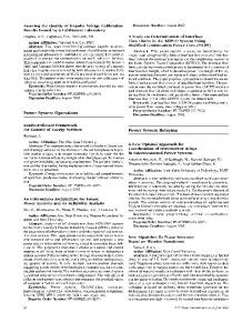
Fig. 9. QSDG of fault vibration propagation in the gearbox.
formances have played an important role in ED/EP systems. Here the miniature sensor module is designed by selecting components carefully from commercial-off-shelf (COTS) products. Two key principles must be considered: lower power consumption, and miniature size. In this case, one three-axial MEMS sensor named LIS3L02AL produced by ST Corporation is used [41]. LIS3L02AL is a low-power 3-axis linear capacitive accelerometer in a 36-pin QFN package, and its size is 6 mm 6 mm 1 mm. The radio transceiver chip is chosen as nRF24E1 produced by Nordic Corporation [42], which is a 2.4 GHz RF transceiver in a 36 pin QFN package, and its size is 6 mm 6 mm 1 mm. When nRF24E1 enters a power down mode, its supply current is only 2 A. The advantage of using nRF24E1 is that it needs other minimal components to complete the hardware design, so that a miniature size can be reached. Finally, the prototype of a miniature sensor module is shown in Fig. 8, and its whole dimension is 9 mm 34 mm 3 mm [43]. A cellular battery model CR2032 can be used to power the sensor module.
Fig. 10. A prototype of ED/EP for the gearbox.
C. Optimal Placement of Embedded Sensor Modules The goal of embedded sensor optimal placement is to embed the minimum number of sensors to cover the maximum number of faults in the gearbox. To improve fault sensitivity, good quality signals with high SNRs are needed, which are tightly related to propagation paths between embedded sensors and fault locations. So fault vibration propagation information is used for embedded sensor optimal placement here. We consider six bearings and four gears as ten candidate locations of embedded sensor modules. Meanwhile, each location represents a potential fault source. Then fault vibration propagation paths can be represented by a signed directed graph as in Fig. 9 [44], where each node represents one component of the gearbox ( , , , , , -bearing; , , , -gear). Each connection between two nodes denotes the interface, and an arrow denotes the direction of vibration propagation. Using “ ” or “ ” for each connection represents signal enhancement or decrement. It must be noted that this QSDG representation only depicts dominant propagation paths in the gearbox obtained by finite element analysis. Each connection is quantified by two weighted values, i.e., travel time, and attenuation of vibration. These two weights can be used to define fault detectability of a sensor [31]. These weighs can be obtained by finite element-based vibration propagation analysis [44], and calibrated by experimental modal analysis. The optimal functions include the maximum fault detectability, and the minimum cost. Then an optimal model is built based on quantitative signed directed graph (QSDG) of
fault vibration propagation [44], which can be solved to determine how many sensors, and where to embed them optimally. In this case, the optimal result corresponds to . D. Integration and Application Finally, a modified gearbox shown in Fig. 10 is designed and manufactured according to the results, and a miniaturized vibration sensor module is designed [43], where the location of sensor 1 corresponds to . Here, the slot is cut from the outer race of the bearing. However, the outer race of the bearing is stationary, so the slot and embedded minimized sensor module will not cause unbalance for the gearbox. For rotating gears, we drill four holes symmetrically to avoid unbalance in the gearbox. It must be noted that unbalance issues should be addressed in practice, in particular on high-speed rotating structures. After assembling, the appearance of the gearbox is also similar to traditional ones, except for an antenna. This configuration can be used to test the feasibility and effectiveness of embedded diagnostics in the gearbox based on vibration signal analysis. An artificial fault is seeded in the inner raceway of a bearing on the input shaft, and its fault frequency is calculated to be 60.2 Hz. Two meshing frequencies of high and low speed gears are 480 Hz, and 125.6 Hz respectively. Then vibration signals from three embedded sensors and an outside sensor on the housing are collected. These signals are analysed, and their power spectrums are shown as Fig. 11(a)–(d). In Fig. 11(a) and (b), the fault frequency can be found. Also we can see that the frequency interval (e.g. 30 Hz) in Fig. 11(b) corresponds to one half of the fault frequency. This observation shows the modulated relations between the half-harmonics and other frequencies, which is indeed caused by the fault. In summary, it is much easier to find frequencies related to the fault (about 60.2 Hz and its harmonics or sub-harmonics) in Fig. 11(a)–(c) than in Fig. 11(d). Thus embedded sensing is better than traditional sensing for gearbox health monitoring. On the other hand, the fault frequency calculated from sensor
CHEN et al.: FRAMEWORK AND ROADMAP OF ED/EP FOR COMPLEX MECHANICAL SYSTEMS IN PHM SYSTEMS
321
ACKNOWLEDGMENT The authors would like to thank Prof. Q. Miao for his suggestions on this paper. REFERENCES
Fig. 11. Comparison of power spectrums from different sensors: (a) sensor 1; (b) sensor 2; (c) sensor 3; and (d) sensor on the housing.
1 is the most obvious among three embedded sensors because sensor 1 is the closest to the faulty bearing, and the SNR is high. Furthermore, the location of sensor 1 corresponds to in the optimal solution, and it demonstrates that the optimal result is feasible. Based on the case study, we can conclude that the ED/EP of the gearbox can be utilized. It is more suitable for on-line health monitoring than traditional methods as it i) provides better SNR, ii) is more sensitive to faults, and iii) can be integrated more easily.
VI. CONCLUSIONS Complex mechanical systems are increasingly used in military and industrial applications. Implementation of PHM is very important to maintain the availability, safety, and economics. This implementation can be achieved through ED/EP, which is an emerging area for complex mechanical systems. This paper proposes a technical framework of ED/EP for complex mechanical systems, and six key elements are summarized. Relationships among these key elements are outlined, and they should be considered simultaneously at the design stage. This paper also looks into the roadmap of ED/EP for complex mechanical systems. While PHM work is abundant for mechanical systems, it is not mature for ED/EP. Our goal is just to shed some light on this research field. In the near future, the authors plan to focus on several fronts. i) We will work on wireless signal transmission on rotating mechanical components. ii) The mechanical structure is often metallic, and it will shield RF signals from embedded sensors, so a reliable wireless signals transmission mechanism will be developed. iii) Power for embedded sensor modules is a challenge because the remaining life of a cellular battery is limited. Energy harvesting (EH) is one potential solution which has been studied widely in recent years [45]–[47]. iv) We plan to develop a prototype ED/EP system.
[1] A. Hess and L. Fila, “The joint strike fighter (JSF) PHM concept: Potential impact on aging aircraft problems,” in Proceedings of IEEE Aerospace Conference, 2002, pp. 3021–3026. [2] A. Hess, G. Calvello, and T. Dabney, “PHM a key enabler for the JSF autonomic logistics support concept,” in Proceedings of IEEE Aerospace Conference, 2004, pp. 3543–3550. [3] G. Smith, J. B. Schroeder, S. Navarro, and D. Haldeman, “Development of a prognostics & health management capability for the joint strike fighter,” in Proceedings of IEEE AUTOTESTCON, 1997, pp. 676–682. [4] E. Scanff, K. L. Feldman, S. Ghelam, P. Sandborn, M. Glade, and B. Foucher, “Life cycle cost impact of using prognostic health management (PHM) for helicopter avionics,” Microelectronics Reliability, vol. 47, pp. 1857–1864, Dec. 2007. [5] W. B. Wang and M. Pecht, “Economic analysis of canary-based prognostics and health management,” IEEE Trans. Industrial Electronics, vol. 58, pp. 3077–3089, Jul. 2011. [6] Kalgren, Patrick, B. Carl, R. Michael, and W. Matthew, “Defining PHM, A lexical evolution of maintenance and logistics,” in Proceedings of IEEE AUTOTESTCON, 2006, pp. 353–358. [7] B. L. Ferrell, “JSF prognostics and health management,” in Proceedings of IEEE Aerospace Conference, 1999, p. 471. [8] P. H. Barton, “Prognostics for combat systems of the future,” IEEE Instrumentation & Measurement Magazine, vol. 10, pp. 10–14, Aug. 2007. [9] L. Christodoulou, “Prognosis,” in Overview talk for DARPA Broad Agency Announcement Call 03-02, Bidders Conference and Workshop, 2002. [10] J. Banks and K. Maynard, Prognostics and Health Management Pennsylvania State University’s Applied Research Laboratory, Technical Report, Mar. 2001. [11] J. Gu, D. Barker, and M. G. Pecht, “Uncertainty assessment of prognostics of electronics subject to random vibration,” in Proceedings of AAAI Fall Symposium on Artificial Intelligence for Prognostics, 2007, pp. 50–57. [12] J. Gu, N. Vichare, E. Tinsley, and M. G. Pecht, “Computer usage monitoring for design and reliability tests,” IEEE Trans. Compon. Packag. Technol., vol. 32, pp. 550–556, Sep. 2009. [13] M. G. Pecht, “A prognostics and health management roadmap for information and electronics-rich systems,” Fundamentals Review, vol. 3, pp. 25–32, Apr. 2010. [14] C. Byington, P. Kalgren, and B. Donovan, “Streamlined avionics PHM utilizing portable information and reasoning,” in Proceedings of IEEE Aerospace Conference, 2005, pp. 3547–3554. [15] M. Lebold and M. Thurston, “Open standards for condition-based maintenance and prognostic systems,” in Proceedings of Maintenance and Reliability Conference, 2001. [16] P. Bardell and W. Mcanney, “Built-in test for RAMs,” IEEE Design Test Comput., vol. 5, pp. 29–36, Apr. 1988. [17] M. G. Pecht, M. Dube, and M. Natishan et al., “Evaluation of built-in test,” IEEE Trans. Aerospace and Electronic Systems, vol. 37, pp. 266–272, Jan. 2001. [18] V. Polis and C. Army, “Vibration and usage monitoring system for the KAMAN SH-2G(A) helicopter,” in Proceeding of DSTO International Conference on Health and Usage Monitoring, 2001, pp. 79–84. [19] G. Victor, C. Adrian, and G. Paulette, “Review of vibration-based helicopter health and usage monitoring methods,” in Proceeding of 55th Meeting of the Society for Machinery Failure Prevention Technology, 2001. [20] D. D. Andrew and D. W. Kensall, “A wireless microsystem for the remote sensing of pressure, temperature, and relative humidity,” Journal of Microelectromechanical Systems, vol. 14, pp. 12–22, Jan. 2005. [21] M. K. Leah and R. Russel, “Embedded diagnostics and prognostics synchronization for army transformation,” in Proceedings of IEEE Aerospace Conference, 2004, pp. 3733–3741. [22] S. F. Cheng, H. A. Michael, and M. G. Pecht, “Sensor systems for prognostics and health management,” Sensors, vol. 10, pp. 5774–5797, Jun. 2010.
322
IEEE TRANSACTIONS ON RELIABILITY, VOL. 61, NO. 2, JUNE 2012
[23] T. H. Brian and X. G. Robert, “A smart bearing utilizing embedded sensors design considerations,” SPIE, vol. 3041, pp. 602–610, Mar. 1997. [24] M. Lin and F. K. Chang, “Development of SMART Layers for built-in diagnostic for composite structures,” in The 13th Annual ASC Technical Conference on Composite Materials, Baltimore, MD, 1998. [25] Embedded Diagnostic & Prognostic Health Management Modules [Online]. Available: http://www.impact-tek.com/Engineering [26] S. Deb, K. R. Pattipati, and R. Shrestha, “QSI’s integrated diagnostics toolset,” in Proceedings of IEEE AUTOTESTCON, 1997, pp. 408–421. [27] P. S. Laura, E. C. James, S. L. Kelly, and B. D. Adele, Algorithm Development for Prognostics and Health Management (PHM) Sandia National Laboratories, Technical Report (SAND2003-3820), Oct. 2003. [28] S. Cheng, K. Tom, L. Thomas, and M. G. Pecht, “A wireless sensor system for prognostics and health management,” IEEE Sensors, vol. 10, pp. 856–862, 2010. [29] F. Belvoir, “DoD 5000.2 Policy Document: Performance based logistics,” in In Defense Acquisition Guidebook, VA, USA, 2004, Chapter 5.3. [30] S. Kenneth, “Embedded sensors for measurement of material properties-needs direction, and technology,” in Proceeding of 41st AIAA/ ASME/SAE/ASEE Joint Propulsion Conference & Exhibit, 2005, pp. 1–12. [31] G. F. Zhang, “Optimum Sensor Localization/ Selection in a Diagnostic/ Prognostic Architecture,” PhD thesis, Georgia Institute of Technology, , 2005. [32] R. F. Charles, P. Gyuhae, and D. Anthony et al., “Sensing and sensor optimization issues for structural health monitoring,” in Proceeding of the 23rd Aerospace Testing Seminar, 2006. [33] G. Venter and S. J. Sobieszczanski, “Particle swarm optimization,” American Institute of Aeronautics and Astronautics, vol. 43, pp. 1583–1589, Aug. 2003. [34] N. Mary and P. G. John, “Use of adaptive model-based reasoning for embedded diagnostics and redundancy management for fault tolerant systems,” Proceedings of IEEE, pp. 455–466, 1997. [35] P. Glynne-Jones, M. J. Tudor, and S. P. Beeby et al., “An electromagnetic vibration-powered generator for intelligent sensor systems,” Sensor and Actuators, vol. 110, pp. 344–349, Mar. 2004. [36] J. Hagerty, F. Helmbrecht, and W. McCalpin et al., “Recycling ambient microwave energy with broad-band rectenna arrays,” IEEE Trans. on Microwave Theory and Techniques, vol. 52, pp. 1014–1024, Mar. 2004. thermoelec[37] J. W. Stevens, “Optimized thermal design of small tric generators,” presented at the Proceedings of 34th Intersociety Energy Conversion Engineering Conference, Society of Automotive Engineers, Vancouver, BC, 1999, 1999-01-2564, unpublished. [38] R. Vijay, K. Aman, and H. Jason et al., “Design considerations for solar energy harvesting wireless embedded systems,” Proceedings of IEEE, pp. 457–462, 2005. [39] T. H. Brian and X. G. Robert, “Structural design and analysis for a sensor-integrated ball bearing,” Finite Elements in Analysis and Design, vol. 34, pp. 257–270, Jan. 2000. [40] X. G. Robert and S. Abhijit, “Diagnosis from within the system,” IEEE Instrumentation & Measurement Magazine, vol. 9, pp. 43–47, 2002. [41] The Product Specification of LIS3L02AL [Online]. Available: http:// www.st.com
[42] The Product Specification of nRF24E1 [Online]. Available: http:// www.nvlsi.no [43] Y. M. Yang, Z. S. Chen, H. Liu, and Z. Hu, “Wireless embedded signals acquisition for mechanical systems,” in Proceedings of IEEE International Conference on Networking, Sensing and Control, 2008, pp. 56–60. [44] Z. S. Chen, Y. M. Yang, C. Li, and J. F. Yin, “Model and algorithm of optimal embedded sensors placement for gearboxes based on signed directed graph of vibration propagation,” Journal of Aerospace Power, vol. 24, pp. 2384–2390, Oct. 2009. [45] J. A. Paradiso and T. Starner, “Energy scavenging for mobile and wireless electronics,” IEEE Pervasive Computing, vol. 4, pp. 18–27, Jan. 2005. [46] R. Torah and G. J. P. M. Tudor et al., “Self-powered autonomous wireless sensor node using vibration energy harvesting,” Measurement Science and Technology, vol. 19, pp. 1–8, Dec. 2008. [47] S. Roundy, “On the effectiveness of vibration-based energy harvesting,” Journal of Intelligent Material Systems and Structures, vol. 16, pp. 809–823, 2005. Z. S. Chen was born in the Anhui Province, China, on Aug. 13, 1977. He received the B.E., and Ph.D. degrees in Mechatronic Engineering from the National University of Defense Technology, P. R. China in 1999, and 2004, respectively. From 2008, he worked as an associate professor in the Key Laboratory of Science and Technology on ILS, College of Mechatronics Engineering and Automation, National University of Defense Technology. His current research interests include mechanical signal processing and data fusion, condition monitoring, embedded fault diagnosis and prognostics, and vibration energy harvesting.
Y. M. Yang was born in the Hunan Province, China, on Apr. 20, 1966. He received the B.E., and Ph.D. degrees in Mechatronic Engineering from the National University of Defense Technology, P. R. China in 1990, and 2008, respectively. From 1992 to 1998, he worked as a lecturer in Institute of Mechatronic Engineering, National University of Defense Technology; from 1999 to 2003 as an associate professor, and then from 2004 as a professor in the Key Laboratory of Science and Technology on ILS. From May, 1998 to May, 1999, he worked as a visiting scholar in the Department of Mechanical Engineering at the University of California, Berkeley, US. His current research interests include modeling and analysis of dynamic systems, condition monitoring and fault diagnosis, integrated diagnostics, and vibration energy harvesting.
Zheng Hu was born in the Hubei Province, China, on Apr. 15, 1972. He received the B.E., and Ph.D. degrees in Mechatronics Engineering from the National University of Defense Technology, P. R. China in 1993, and 1998, respectively. From 2007, he worked as a professor in the Key Laboratory of Science and Technology on ILS, College of Mechatronics Engineering and Automation, National University of Defense Technology. His current research interests include Design for testability, embedded fault diagnosis and prognostics, mechanical signal processing, and internet of things.