Jul 7, 2010 - A TELEMETRY MODELING FOR INTELLIGENT UAV MONITORING. Joshua Tristancho, Cristina ... aircraft system in an open source flight simulator. Introduction .... bandwidth using 64 bits per second. Figure 5. Telemetry ...
A TELEMETRY MODELING FOR INTELLIGENT UAV MONITORING Joshua Tristancho, Cristina Barrado, Sonia P. Mansilla, Enric Pastor UPC, Castelldefels, Barcelona (Spain)
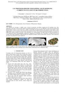
Abstract An Unmanned Aerial Vehicle, UAV for short, is able to fly autonomously during all phases of flight, but has to be monitored from an operator station. In this article a better avionic system is proposed to optimize this process reducing the channel usage without quality degradation. The information related to the aircraft position is called telemetry. This early avionic system is tested in the longitudinal mode of a high wing model unmanned aircraft system in an open source flight simulator.
If this early avionic system fails, then the system works as usual and the telemetry is received by the ground station in order to be monitored. The remote control schema showed in Figure 1 is an example of control loop where decisions are taken by the ground controller. This case requires a constant two-way communication link known as full duplex channel. Remote controlling is used when the ground controller takes the control of the UAV and is called telecommanding.
Introduction The vehicle behavior can be modelized by the equations of movement then we can transmit once the parameters which define these equations instead of sending constantly the position. These equations are well known[1] and are not the purpose of this paper. A single dimension UAV oscillation, for example a Phugoid mode, could be defined by four parameters: • • • •
Initial position Proportional constant Natural frequency Damping coefficient.
Figure 1. Control Loop by Ground Controller The early avionic system we propose is useful for monitoring the UAV. The information related to the aircraft position is called telemetry. In Figure 2, the telemetry generated is downloaded to the ground controller but also received by the onboard controller, known as autopilot (AP). The autopilot closes the control loop taking action over the UAV surfaces.
The early avionic systems we present will detect these equations analyzing the same information that is generated for the positioning subsystem[2]; for example the Global Positioning System GPS or the Inertial Navigation System INS. In normal conditions, the scheduled flight of an UAV will be done as predicted by the early avionic system. If any of those parameter experiments a significant change, then only the modified parameter is sent to the ground station. That way an intelligent use of the communication channel is achieved.
978-1-4244-4078-8/09/$25.00 ©2009 IEEE.
Figure 2. Control Loop by an Onboard Autopilot
7.C.1-1
Authorized licensed use limited to: UNIVERSITAT POLITÈCNICA DE CATALUNYA. Downloaded on July 07,2010 at 12:04:18 UTC from IEEE Xplore. Restrictions apply.
In an UAV, remote controlling is used, for example, when an emergency operation requires human piloting, but remote controlling is not the most used in-flight configuration.
Architecture The system is composed by two main parts, the unmanned aerial vehicle and the ground station. Between both parts a radio-link is required. Each part is composed by modules as showed in Figure 3.
Figure 3. System Architecture
The positioning module provides information in order to send the telemetry to the ground operator. At the same time, the oscillator detector module generates near-real-time parameters which describe the UAV oscillation. Only the telemetry or the oscillator parameters are sent to the ground station but not both. On ground, an oscillator generator produces a synthetic telemetry based on the parameters calculated by the oscillator detector. The real telemetry or the synthetic telemetry is transferred to the monitor module.
from the unmanned aerial vehicle in order to be monitored.
Onboard Algorithm
If no information about the aircraft oscillation is available then the whole telemetry is sent to the ground station. If the oscillator detector identifies an oscillator mode then the parameters of the new flight model are sent to the ground station. If any oscillator parameter changes then only new parameters are sent to the ground station.
Algorithm The algorithm is divided in two parts one onboard and one in ground.
If all oscillator parameters change then the whole telemetry is sent again until the oscillator detector identify any sustained flight configuration.
The requirement for the onboard part is as follows: The unmanned aerial vehicle sends to the ground station the related information to be monitored.
If the oscillator detector can’t identify any oscillation mode then the system works as usual. In this case telemetry is received by the ground station in order to be monitored.
The requirement for the ground part is as follows: The ground station receives the information 7.C.1-2
Authorized licensed use limited to: UNIVERSITAT POLITÈCNICA DE CATALUNYA. Downloaded on July 07,2010 at 12:04:18 UTC from IEEE Xplore. Restrictions apply.
Table 1. Bit Rate and Total Transferred Bits
In Ground Algorithm
Take-Off Case Whole telemetry Optimized bandwidth Using ephemeris
If the information received by the ground station is the real telemetry then this information is passed to the monitoring module. If the information received by the ground station are oscillator parameters then the oscillator generator produces a synthetic telemetry based on the parameters defined by these parameters. This synthetic telemetry is passed to the monitor module.
Bit Rate 640 bps 64 bps N/A
Total 106 kb 11 kb 5.4 kb
Results are post-processed in order to model the aircraft behavior. Table 1 shows the results of the test and the implemented algorithm. The telemetry bit rate is 640 bits per second. The quantity of information transmitted by the communication channel is: 3400 * 32 = 106.25 kilobits
Discussion of Results We will discuss the results done in the longitudinal mode analyzing the vertical position as a function of time. The following test was performed by a Cessna 172 flight model in a simulator[3] similar to many high wing unmanned aerial vehicles. We used FlightGear[4] to simulate a take-off flight and a climb pattern. The transmission channel was modeled using a network in order to simulate any stochastic delay. We have used Matlab[5] in order to post-process the data. The bandwidth used in the transmition channel for this test is 20 Hz. In Figure 4, a graphic with a telemetry example is shown. This example corresponds to 170 seconds of flight or 3400 samples. In this graphic the vertical mode produced by the positioning system is drawn. The abscissa axis measures units of samples; in this simulation there are 20 samples per second. Each telemetry package is formed by a 32-bit float[6] corresponding to the aircraft altitude. We can distinguish two patterns: The Run-up pattern and the Climb pattern.
The frequency spectrum analysis (Figure 5) shows that, based on the well known NyquistShannon[1] sampling theorem, in this flight only 2 Hz are required. It is possible to optimize the channel bandwidth using 64 bits per second.
Figure 5. Telemetry Frequency Spectrum. Power Spectral Density Vs Frequency In the optimized case the quantity of information transmitted by the communication channel is: 340 * 32 = 10.63 kilobits In Figure 6, the frequency spectrum shows the existence of an oscillator in the band corresponding to a Phugoid mode[1].
Figure 4. Telemetry Example. Altitude Vs Samples
Figure 6. Optimized Telemetry Frequency Spectrum. Power Spectra Density Vs Frequency 7.C.1-3
Authorized licensed use limited to: UNIVERSITAT POLITÈCNICA DE CATALUNYA. Downloaded on July 07,2010 at 12:04:18 UTC from IEEE Xplore. Restrictions apply.
The telemetry showed by the ground monitor is presented in Figure 7. Before send the parameters, the telemetry is marked as a dotted line. When the parameters are sent is marked by a triangle. Beyond this event, the synthetic telemetry is marked with continued line.
Future Work The early avionic system requires many improvements: • Additional axis has to be implemented. • Apart of the longitudinal mode, lateral mode has to be implemented in order to see the efficiency when the vehicle turns. • The early avionic system has to be tested with real telemetry. • It has to be tested on different types of unmanned aerial vehicles flying several types of maneuvers.
References
Figure 7. Telemetry Produced by the Ground Monitoring. Altitude Vs Samples We have observed that the oscillator detector algorithm requires two complete oscillation cycles in order to determine the four basic parameters of an oscillator. This event (marked as a triangle) occurs near to the sample 1700 which means that we used 5.32 kilobits to detect a sustained flight configuration. If the aircraft follows its predicted path, it is unnecessary to transmit the rest of telemetry. It can be generated a synthetic telemetry on ground; saving, for the previous example, the 50% of channel use. The quantity of information transmitted in this case by the communication channel is: 170 * 32 + 4 * 32 = 5.44 kilobits
[1] Anderson, J., “Introduction to fight," Tech. rep., McGraw Hill, 2000. [2] Chad Andrade. Leonardo, et all. 2009, “A Novel Approach to Integrated GPS/INS Tracking”, IEEE Aerospace Conference, paper #1709. [4] FlightGear http://www.flightgear.org/ (July 2009) [5] Matlab http://www.mathworks.com/ (July 2009) [3] EPSC (UPC) http://epsc.upc.edu/ (September 2009) [6] 754-2008, “IEEE Standard for Floating-Point Arithmetic”, D.O.I. 10.1109/IEEESTD.2008.4610935.
Acknowledgements
Conclusions This paper presents an early avionic system useful for monitoring UAVs by the ground controller. The longitudinal mode was tested for a high wing model unmanned aircraft system and using the open source flight simulator called Flight Gear. In the implementation of the algorithm was used Matlab but it has to be implemented in a real avionic device in a real unmanned aerial vehicle. With this early avionic system, we have not only a more efficient channel usage but also a more intelligent monitoring because we use the communication channel only when required.
This work has been funded partially by Ministry of Education of Spain under contract number MEC TIN2007-63927 and by EUROCONTROL under contract 08-120916-C. The first author wants to acknowledge Escola Politècnica Superior de Castelldefels[6] from the UPC University in Barcelona, Spain, for the support in the CESSNA® 152 cabin simulator facility. CESSNA® is a trademark of Cessna Aircraft Company. http://www.cessna.com/
28th Digital Avionics Systems Conference October 25-29, 2009
7.C.1-4
Authorized licensed use limited to: UNIVERSITAT POLITÈCNICA DE CATALUNYA. Downloaded on July 07,2010 at 12:04:18 UTC from IEEE Xplore. Restrictions apply.