A Unified Approach to Evaluation and Design of Hardware/Software Systems Zebo Peng, Johan Fagerström and Krzysztof Kuchcinski Department of Computer and Information Science Linköping University S-581 83 Linköping, SWEDEN Email:
[email protected]
Abstract This paper presents a unified approach to the design of application-specific systems which consist of both hardware and software components. Our approach is based on the development of an formal intermediate design representation which can be used to capture both hardware and software semantics. Evaluation of a hardware/software design can then be done automatically by simulating the design representation. The simulation results can directly be used to guide exploration of the design space so as to produce cost-effective solutions. The proposed approach supports a top-down design methodology which starts with a high-level behavioral specification and transforms it step-bystep into an efficient implementation by making design trade-offs between hardware and software.
1. Introduction Most application-specific systems in information technology consist of both hardware and software components. The design space of such systems is huge and multi-dimensional. One way to handle the complexity is to equip the designers with efficient mechanisms to explore the design space and make appropriate decisions. We also need a new view of system design which treats the hardware part and the software part as integrated components of the system. Traditionally, the hardware and software design paths separate early in the design cycle and once departed, they do not come together until it is almost time to ship a product [Har 90]. In such a situation, software design is dictated by hardware design decisions that were made during the first phase of system design. Software development does not track changes made during the hardware design cycles, nor does it influence hardware design. At the same time, it is impossible to move functionality from the hardware domain to the software domain or to change the hardware/software interface to improve the overall design of a system. Therefore, a strict separation of the design activities into two distinct domains does not work well. Recent research activities trying to remedy this problem include [Phi 90] and [Ste 90]. We are developing a design methodology which allows a total integration of the software and hardware design activities. In particular, we will develop a silicon/software compilation environment that will allow system designers to start the design process with a very high level language specification and generate a hardware implementation at register-transfer level as well as a software program which together will implement the given specification. Our approach is based on a unified design representation which captures
-1-
design results in the intermediate design stages so that hardware/software trade-offs can be easily made and evaluated. Partition of a system into software sub-systems and hardware sub-systems can be done efficiently based on this design representation. The results of the partitioning can then be compiled into corresponding implementations. This paper presents first an overview of the design environment we are developing and then concentrates on the description of the design representation and its evaluation technique. The design representation is based on an extended timed Petri net notation (ETPN) [Pen 88a] which has been successfully used in a VLSI synthesis system. The main features of the Petri net based notation include the explicit description of parallel computation and data dependency relation, which are also the major ingredients of a software design. Therefore, the Petri net based notation is adopted to describe hardware/software designs. A simulation tool has been developed to “execute” the design representation so as to collect performance statistics as well as to check the functional correctness of the design representation. The statistics information can be used to evaluate the current design and guide the design transformation in the design process. Our ultimate goal is to provide a set of automatic or semi-automatic tools which allow the designers to quickly explore the hardware/software design space of different solutions.
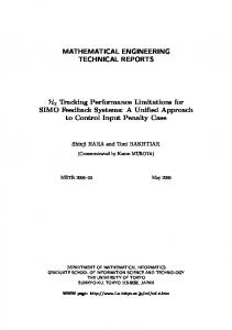
2. Overview of the Design Environment The overall structure of our system is shown in figure 1. We briefly discuss each part in this section, later sections will present more details. The starting point is a set of design constraints together with a behavioral specification in the form of a program written in a very high level language. The language has not yet reached its final form so we only outline important aspects of the language here. There are two, contradictory, goals: • The programmer should be allowed the freedom to specify the problem in an architecture independent abstract notation.
This picture is not available on line; please contact one of the authors for a paper copy.
Figure 1. Overview of the proposed design environment -2-
• The compiler front-end must generate an intermediate representation which is useful for later phases in the design environment. This includes low-level implementation details such as data structure representations. We have, therefore, divided our specification language into one programming languages, a very high level language suitable for functional specification, and one annotation language, used for architecture dependent information and design constraints. We use a general-purpose programming language based on Pascal extended with data parallel constructs. The language also includes an advanced typing mechanism and user-definable high-level views on data structures similar to views in Booster [Paa 90] and shapes in Paralation Lisp [Sab 88]. The programmer can to some extent introduce new syntax for high-level views on data. For instance, a view specifying matrix diagonals can be defined and new syntax introduced to allow short and concise matrix algorithms to be written. The annotation language is used to provide (optionally) extra information such as known limits on data values or suitable internal representations of high level data structures. It is also used for design constraint specification. For instance, one can specify the maximum time delay in a specific function. The compiler front-end does a thorough program analysis, supported by the detailed information extracted from typing and view constructs in the program and extra information in the annotation language. The compiler also does data structure selection [Sch 81]. It initially uses a default implementation (such as a bitmap for sets) which later can be changed based on simulation results. The knowledgeable programmer can override the default using the annotation language. The compiler front-end does also parallelism extraction using data-flow dependance analysis techniques. It generates as output an initial design representation in the Petri net based notation. The Petri net based design representation is used to capture the intermediate results of design transformations/optimization. This representation captures explicitly parallel computations and allow the partitioning of hardware/software to be done in different ways. It is formal and executable, which allows the designer to use verification and evaluation techniques to analyze the intermediate design and make appropriate design trade-offs. One of the evaluation techniques we have implemented is a simulator which executes the design representation with typical input stimuli and collects statistics about data usage and control flow choices in a given design. The partitioner uses design constraints, the intermediate representation and performance statistics to partition the design into software and hardware sub-systems. After the partitioning is done, the hardware implementation is generated by CAMAD [Pen 88b], a silicon compiler, which is built around the ETPN design representation. The hardware implementation is considered as a specialized co-processor which will be controlled by and interact with the software generated by a compiler.
3. The Unified Design Representation The proposed design representation is based on a Petri net notation which allow us to describe the partial ordering relation over a set of places and transitions [Pet 81]. The places are used in our approach to represent operations and the transition synchronization of a system. If two operations are not in the partial ordering relation, they are causally independent and may occur in either order or simultaneously. Therefore, the partial ordering of operations can be used to express the concurrent and asynchronous aspects of a hardware/software system. The Petri net notation is extended to include a set of data flow graphs with a single assignment assumption. Each Petri net place is associated with a data flow graph. Each node of the data flow graph specifies the operation to be performed, the set of variables which are used by the operation, and the set of variables which are assigned by the operation. The arcs in the graphs describe the data dependencies between the opera-
-3-
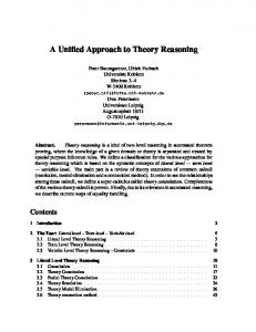
tions. These operations are to be performed according to their data dependency orders when their corresponding place is holding a token. A data flow graph corresponds roughly with a block of the input specification program which has a single entry point. A similar approach of using data flow graph to specify operations is proposed by [Pat 90], which is utilized in a VLSI synthesis system. Our approach differs from related work in intermediate representation for software compilers which concentrates on the syntax information [Fri 86]. The Petri net based notation is designed in first place to capture the semantics of a given specification. An example the Petri net based notation is illustrated in figure 2(a) and 2(b). Figure 2(a) depicts a Petri net which describe the control flow of a program or a hardware circuit. A control state is defined as a marking of the Petri net, i.e., the possession of tokens in a subset of the places of the Petri net which are depicted as circles. The transitions of control states are represented as firings of one or several transitions of the Petri net which are depicted as bars. Different from ordinary Petri nets, the transitions can be guarded by a set of conditions which must be true before the transitions can be fired. The guarding conditions are computed by the operations defined in the dataflow graph depicted in figure 2(b). Figure 2(a) and 2(c) together defines the corresponding ETPN description of the same example. The ETPN design representation consists also of separate but related models of control and data path. The data path of
P1: #0 Y
X
X
P2 C
C P6
C P5: I
Y
P4: X
P6: Y
#0
≥
I
P3: IN P1
P2: X
#0 #0
#1
+
+
Y
I
I
Out1 Out2
P3 (b) Dataflow graph
P5 #0 P1
P4
#0 P1
Y (a) Control Petri net
P3 #0
X P4
P4 P4 P6
#0 P1
IN
+
P2
Out1
≥ C (c) Data path
Figure 2. An example of the design representations
-4-
P5
P2
P2
#1
I
+ P6 Out2
P5 P5
ETPN is represented as a directed graph with nodes and arcs. The nodes are used to capture data manipulation units (hardware modules). The arcs represent the connections of the nodes. The ETPN control part is captured as a timed Petri net with restricted transition firing rules. We have introduced timing information into the ETPN notation to facilitate performance analysis. Each place in the ETPN control part is associated with a time which modifies the firing rule of the Petri net. A token must now stay in the place for at least the given amount of time before it can be used to fire a transition. This timing information is used to model the operation delay associated with the hardware modules used to implement the operations associated with the place. For a formal definition of ETPN, see [Pen 88a]. It can be seen from the above example that the Petri net based unified design representation is very similar to ETPN. This is true only when the ETPN is first generated after the partitioning of hardware and software is done. As soon as hardware related transformations are applied to the ETPN design, the similarity will be reduced. For example, the two adders in the data path of ETPN can be merged together to reflect the design decision to share one hardware unit by two operations. However, the transformations from the ETPN data path to the dataflow graph notation can be done if so desired and vice versa, which provides the possibility of moving the hardware/software boundary during the design process. The unified design representation is also sometimes converted to the ETPN notation to make use the currently available analysis tools we have implemented for ETPN. The main feature of our design representations is their ability to capture the intermediate result of a design explicitly so as to allow the design algorithm to make accurate design decisions. For example, given an intermediate result represented in ETPN, an algorithm can be used to estimate its implementation cost, check whether that satisfies the design constraints, and automatically choose a transformation to apply to the design which produces another intermediate result with improved cost. ETPN, for example, is used by the CAMAD hardware synthesis system [Pen 88b] to support an iterative transformation approach to carry out the synthesis tasks. CAMAD first generates a preliminary (default) design in ETPN format from the input specification. It then applies transformations one by one to the preliminary result so as to obtain better solutions. This iterative process is finished when satisfactory results have been reached. The data path is then transformed into a net-list and the control Petri net into a microprogram. The proposed silicon/software compiler environment will use the same strategy.
4. Simulation and Evaluation In order to guide the design transformation process (to select which transformation to apply in each design step), we need a precise way of evaluating the intermediate designs as well as the final implementations. Evaluating design alternatives with different partitioning of a system and different trade-offs between implementation technologies is an important part of the design space exploration activities. We have developed a simulator for this evaluation purpose. The simulator can be used to verify a system’s functionality and check if the given design constraints are satisfied. Since the ETPN notation can represent timing information, the validation checking includes both timing and performance analysis. Further, the simulator give as output a dynamic profile of the system behavior. This information can be used to guide design steps, such as system partitioning and finding critical regions of a design. The functional verification is achieved in the current simulator by executing the ETPN design representation, which is similar to ordinary program execution. A system represented by ETPN is executed for a given input data. The input data can be enumerated by the user or generated randomly by the simulator. Sequences of data which are within certain limits can be also defined. In addition to automatically generated data, an interactive mode is also supported. The simulator produces output data as well as a simulation trace which represents the dynamic system behavior. The simulation trace can be inspected later to verify functional and timing properties of the system under design.
-5-
The output data consists of basically the dynamic profile information, which gives an average estimation concerning different parts of the design. Currently the following information is collected by the simulator: • the utilization of every data path node which reflects the use of variables/registers, operators/functional units, etc.; • the probability that a given condition is true during the execution which contributes to the information about critical regions of the design; • an estimation of system performance in respect to a starting place and a terminating place which gives the information about execution of critical parts of the design; and • repetition counts of loops. This information has proved to be very useful for design optimization as well as the silicon/software compilation process. In the early stage of the design process it can be used to make decisions about system partitioning as well as function distribution between software and hardware. On the later stages it can be used to guide the optimization process and help the selection of proper regions of the design to perform optimization transformations first. In silicon compilation, for example, it provides utilization data of individual ALU, register, bus, etc., which is vital to the hardware allocation algorithm [Pen 88b].
5. Some Design Algorithms This section will briefly discuss how the design representation and its simulation results can be used in the design process by sketching some of the major design algorithms/steps in our approach. Note that some of the ideas described here have not yet been fully implemented. The first thing we will discuss is the partitioning algorithm. It makes heavily use of the simulation results, especially the critical regions identified by the simulator. The partitioner will, for example, “allocate” hardware for most performance-critical parts and leave the rest for less expensive software implementation. Before partitioning, the Petri net based representation is translated into a graph representation by mapping its basic elements to vertices and edges of a graph notation. The translation maps places together with their related data nodes to graph vertices while graph edges are created based on the Petri net and data path connectivity. The statistics information is used to calculate the weights assigned to the graph’s vertices and edges. The generated graph can then be partitioned by a graph partitioning algorithms. A simulated annealing algorithm has been implemented to perform the graph partitioning task. After the partitioning is done a silicon compiler can be used to synthesize the hardware part and a software compiler the software part. We use the CAMAD system to perform the synthesis of hardware. CAMAD is a register-transfer level synthesis tool built around the ETPN representation. It consists of a set of hardware synthesis transformation algorithms. These algorithms manipulate both the data path and the Petri net to reflect design decisions made about operation scheduling and hardware allocation. A critical-path based optimization algorithm decides the order of these basic synthesis transformations so as to move the preliminary design towards the optimal or near optimal one. The final design is then translated by CAMAD into a netlist which can be input to a logic synthesis tool to generate the final layout design. The software implementation can be generated from the Petri net based notation using ordinary compiler technique. The software is used both to implement part of the system functionality and to produce control signals to drive the hardware structure.
6. Summary This paper presents a unified approach to representing, evaluating and designing hardware/software systems. It concentrates on the intermediate design representation and its simulation/evaluation. The work presented here is part of a large project which aims at the development of a design environment of integrat-6-
ed hardware/software codesign. Much remains to be done to achieve a total integration, but we strongly believe that the development of a formal unified design representation is a major step towards an integrated environment.
7. References [Fri 86] Fritzson, P., A Common Intermediate Representation for C, Pascal, Modula-2 and Fortran-77, In Proc. of the Workshop on Compiler Compilers and Incremental Compilation, Bautzen, DDR, October 12-17, 1986 [Har 90] Harding, H., Mixed CASE and CAE/CAD Tools Ease Designers' Headaches, Computer Design, Vol.29, No.1, Jan. 1990, pp.74-88 [Paa 90] Paalvast, E., Gemund, A. and Sips, H., A Method for Parallel Program Generation with an
Application to the Booster Language, Proceedings of the 1990 ACM Fourth International Conference on Super-computing, Amsterdam, June 11-15, 1990 [Pat 90] Petal. M., A Design Representation for High Level Synthesis, Proc. of the European Design Automation Conf. , Glasgow, Scotland, Mar. 12-15, 1990, pp.374-379 [Pen 88a]Peng, Z., Semantics of a Parallel Computation Model and its Applications in Digital Hardware Design, Proc. of the 1988 International Conference on Parallel Processing, Pennsylvania State University, August 15-19, 1988, pp.69-73 [Pen 88b]Peng, Z., Kuchcinski, K. and Lyles, B., CAMAD: A Unified Data Path/Control Synthesis Environment, in D.A. Edwards (Editor), Design Methodologies for VLSI and Computer Architecture, North-Holland, 1988, pp.53-67 [Pet 81] Peterson, James L., Petri Net Theory and the Modeling of Systems, Prentice-hall, Englewood Cliffs, New Jersey, 1981 [Phi 90] Philipson, L., Multilevel Design and Verification of Hardware/Software Systems, IEEE Journals of Solid-State Circuits, Vol.25, No.3, 1990, pp.714-719 [Sab 88] Sabot, G., The Paralation Model, The MIT Press, 1988 [Sch 81] Schonberg, E., Schwartz, J. and Sharir M., An Automatic Technique for Selection of Data Representations in SETL Programs, ACM Transactions on Programming Languages and Sys-
tems, Vol.3, No.2, April 1981, pages 126-143 [Ste 90] Stevens, M. and Budzelaar, F., System Level VLSI Design, Microprocessing and Microprogramming, the EUROMICRO Journal, Vol.30, 1990, pp.321-329
-7-