2240
IEEE TRANSACTIONS ON CIRCUITS AND SYSTEMS—I: REGULAR PAPERS, VOL. 54, NO. 10, OCTOBER 2007
A Versatile Variable Rate LDPC Codec Architecture Colm P. Fewer, Mark F. Flanagan, and Anthony D. Fagan
Abstract—This paper presents a system architecture for low-density parity-check (LDPC) codes that allows dynamic switching of LDPC codes within the encoder and decoder without hardware modification of these modules. Thus, rate compatibility is facilitated without the performance degradation inherent in a puncture-based system. This versatility also allows the LDPC system to be used in a variety of applications since the encoder and decoder can be used with codes that span a wide range of lengths and rates. Index Terms—Implementation, low-density parity-check (LDPC) codes, puncturing, rate-compatible, versatile.
I. INTRODUCTION
L
OW-DENSITY parity-check (LDPC) codes have received a great deal of attention in the literature over recent years since it was discovered that they have very good error correcting performance over a variety of channel types. Originally discovered by Gallager [1] in 1962, LDPC codes were independently rediscovered by MacKay [2], [3] and by Luby et al. [4]. Since this time, much work has been carried out on the design of good codes and on the analysis of their performance [5]–[7]. Although the primary goal of any error correcting code is to achieve a performance that is close to the Shannon limit, it is ultimately just as important that they lend themselves to practical implementations so they can be integrated into real systems. Thus, the requirements of an LDPC communications system may be prioritized as follows. 1) The LDPC code must provide error-correcting performance as close as possible to the Shannon limit. 2) The encoder and decoder implementations for the code must perform at high throughputs to accommodate the data-rates of modern communications systems. 3) The encoder and decoder must make efficient use of logic resources. The random nature of the connections between nodes in the bipartite graph of a typical LDPC code means that decoders in particular are difficult to implement efficiently in a fully parallel fashion and are not scalable [8]. This is well recognized in the most recent work on decoder architectures [9]–[12] and has prompted a move to partially parallel implementations. It is also becoming commonplace to construct the LDPC code in unison with the decoder so that the implementation can benefit from the structure of the code, although this process often neglects the complexity of the encoding process. Most decoder architectures (with [11] being one exception) have some portion of Manuscript received April 5, 2006; revised October 4, 2006. This work was supported by the Informatics Commercialization initiative of Enterprise Ireland. This paper was recommended by Associate Editor F. C. M. Lau. The authors are with the University College Dublin, Dublin 4, Ireland (e-mail:
[email protected]). Digital Object Identifier 10.1109/TCSI.2007.904641
their architecture fixed to a specific code, which means that the decoder must be redesigned in order to accommodate codes of different rates or lengths. In [11], the code requires significant storage and so it is somewhat impractical to facilitate multiple codes. In terms of LDPC encoding, the traditional method involves the multiplication of the message bits with the generator matrix (constructed from the parity-check matrix). Since the generator matrix is typically dense, the computational complexity of this . Specific families of LDPC codes such as operation is Repeat-Accumulate codes inherently lend themselves towards efficient encoding, but often at the expense of decoder complexity. More recently, it has become common to base encoder architectures on Richardson and Urbanke’s work [13], which admits nearly linear encoding complexity [12], [14]. Of these, only the parallel implementation provided in [12] meets the high bandwidths required of modern systems. However, this design is fixed to a specific code and provides little flexibility. One desirable feature mentioned is the ability to facilitate dynamic switching of LDPC codes in both the encoder and decoder. This would allow new use models for such a codec implementation. • Rate compatibility is a vital facet of any transmission system that operates over a time-varying channel. The ability to dynamically switch codes would allow a variable rate system to be built without the need for puncturing. In addition to the logic savings, transmissions at higher code rates would not suffer the performance degradation inherent in puncture-based systems. • The ability to use a single encoder-decoder pair for a wide variety of code rates and lengths means they could be used in an equally wide variety of applications. Ultimately, this means that hardware costs would be reduced since it would not be necessary to redesign these modules for every new application. Sun et al. [15] proposed a generalized decoder structure, but it handles only regular codes and uses the min-sum decoding algorithm which has a significant negative impact on code performance. As mentioned, Lee et al. introduced a flexible encoder design [14]. However, the throughput of this implementation is too low to be useful for practical applications. This paper introduces a block-structured methodology for LDPC code synthesis. The code is constrained using [13] as a guideline and the resulting codes have a very low memory footprint. A partly parallel encoder is then designed using the constructed codes. This implementation provides high throughput, is remarkably compact and allows dynamic switching of codes. The structural constraints applied to the code allow us to build on the decoder in [11], performing several optimizations at the architectural level. The resulting decoder is more efficient and has higher throughput, and also
1549-8328/$25.00 © 2007 IEEE
FEWER et al.: VERSATILE VARIABLE RATE LDPC CODEC ARCHITECTURE
2241
Fig. 1. Concurrent design flowchart of encoder, decoder, and LDPC code.
allows the dynamic switching of codes. This unified architecture of code, encoder and decoder yields a practical high-speed codec implementation for LDPC codes while providing a very high level of versatility. II. CODE CONSTRUCTION METHODOLOGY The code design uses the concept of irregularly partitioned permutation matrices (IPPMs) [10], [16], [17]. This construc“macro-matrix” with tion involves construction of a small the desired properties. This matrix then undergoes a scaling perprocess, where each nonzero entry is replaced by a mutation submatrix and each zero entry is replaced by a zero matrix. The submatrix can be either a pseudorandom permutation or some cyclic shift of the identity. In general, the submatrix contains one 1 per row and one 1 per column so that the expanded matrix maintains the degree distribution of the macro-matrix. The resultant parity-check matrix has dimension . A. Construction Constraints A concurrent design methodology is used to ensure that the code, the encoder and the decoder are all architected with an awareness of one another. A series of constraints are passed between the encoder and decoder design processes to the code construction process, as depicted in Fig. 1. The following code construction constraints are derived from the encoder architecture (see Section III). • The encoder requires that the LDPC code be designed with an IPPM-type structure. • The expansion submatrices must take the form of a shifted identity matrix. • It must be possible to convert the macro-matrix for the code into an approximate lower triangular (ALT) form as shown in Fig. 1. The gap value for the conversion must be 1. • Following the ALT conversion and the expansion of the must be macro-matrix, the matrix invertible. In addition to the encoder constraints, following code construction constraint is derived from the decoder architecture (see Section IV). • The expansion factor has a direct relation to the number of computational modules required in the decoder, so a
careful balance must be struck between this parameter and the code length. B. Construction Procedure With the aforementioned hardware-based constraints and with the implicit constraint of ensuring good error correcting performance, the code construction methodology may now be described as follows, with reference to Fig. 3. 1) Choose code parameters. • Choose code length and rate. • Choose expansion factor based on maximum desired hardware complexity (encoder and decoder). 2) Choose degree distributions. • Select degree distribution based on optimal values from [18]. 3) Fill macro-matrix. • Pseudorandomly fill nonzero entries of the macro-matrix according to degree distributions. • Ensure no cycles exist consisting solely of weight-2 variable nodes. 4) Perform expansion based on approximate cycle extrinsic message degree (ACE) criteria [19]. • Expand the macro-matrix by replacing each nonzero . entry with a shifted-identity submatrix of size The expansion process converts the rows and columns of the macro-matrix in to “block rows” and “block columns” in the expanded form. • Use ACE criteria to choose shift values so that harmful cycles are removed using a modified implementation of the theory in [20] (including those of length 4). This helps to ensure that the codes have a low error floor. 5) Perform ALT conversion. • Perform ALT conversion using a modified form of the Greedy Algorithm A (from [13]). • Ensure the gap is 1. 6) Check Invertible. • Ensure that can be inverted. In practice this is almost always possible. 7) Completion. • Store the ALT form of the macro-matrix and the shift associated with each nonzero entry. • Store (dense matrix).
2242
IEEE TRANSACTIONS ON CIRCUITS AND SYSTEMS—I: REGULAR PAPERS, VOL. 54, NO. 10, OCTOBER 2007
III. VERSATILE ENCODER ARCHITECTURE A. Efficient Encoding
Fig. 2. Macro-matrix in approximate lower triangular form (from [13]).
The versatile LDPC encoder uses an extended version of the encoding technique presented in [13]. The involves converting the parity check matrix into ALT form as shown in Fig. 2. Since this is obtained solely by using row and column swaps, the remains sparse. By letting the codeword ALT form of , where denotes the user data portion of the codeword, and combined denote the redundant portion of ) can be the codeword the parity check equation ( rewritten as (1) Multiplying from the left by
and solving, we get (2) (3) where . and and, hence, genThus, it is possible to determine erate the codeword for using partitions of the ALT form of . Note that calculations involving can be performed as forward substitution operations since , which can be solved since is lower triangular. With the exception of multiplication by , the processing time required for all of the computations is proportional to the number of nonzero entries in the macro-form of the partition being operated on. Since each of these partitions are sparse (since the ALT form of is sparse), the total computation time . The single operation that involves is approximately is . However, since is equal to 1 for the macro-matrix this calculation has only a modest affect on the overall computation time. We now extend this algorithm to cover circulant IPPM-type matrices. In order to do this, the different computations involved in the encoding operation are identified and then generalized for IPPMs, so that they may all be handled by a single calculation engine. From (2) and (3), the computations can be divided into three classes, described in the following section. Fig. 3. Flexible code construction flowchart.
B. IPPM Encoding Operations A major advantage in constructing codes using this technique is that the macro-matrix is small. As a result, the generation and expansion of this matrix and checking the suitability of the resulting code for encoding may be performed rapidly. Thus, if a particular code in the ensemble does not meet the requirements, it can be discarded and another generated instead. Given typical degree distributions and an expansion factor , it is possible to generate a suitable code in a very short time from the ensemble.
1) Macro-Multiplication: Macro-multiplication is the term given here to the process of performing matrix-vector multiplication operations using IPPMs. Consider the following case of the equation :
.. .
.. .
..
.
.. .
.. .
.. .
(4)
FEWER et al.: VERSATILE VARIABLE RATE LDPC CODEC ARCHITECTURE
2243
where each submatrix is either a zero matrix or shifted and are 1 subvectors. A subidentity matrix and each is calculated as vector
code construction algorithm) and the resulting matrix is nonis a dense circulant matrix composed of singular, then the superposition of several shifted identity submatrices. Thus
(5) All of the terms for which is a zero matrix can be ignored. as an operator which For the remaining terms, denote cyclically shifts a vector by the shift value associated with . is equivalent to a cyclic Since multiplication of a vector by shift of the vector, we can rewrite (5) as
where are the component shifts that make up and . As a result of this structure, multiplication by can be decomposed into a series of multiplications by the constituent elements that make up the matrix
(6)
In summary, all of the computations required by the encoding procedure can be reduced to a combination of vector cyclic addition operations. Thus, an efficient encoder shifts and may be implemented by constructing a small high-speed computation engine to perform these operations.
Thus, the entire computation can be reduced to a series of shiftand-add operations. Since the majority of the entries in a typical matrix are zero, the number of shift-and–add operations for the entire macro-multiplication is equal to the number of nonzero submatrices within , which is small since the macroform of is sparse. 2) Macro-Forward Substitution: Macro-forward substitution is the term given here to the operation of performing forward substitution using a partition of an IPPM. Consider the case of where is the unknown vector. Multiplying by on both sides, we obtain
.. .
.. .
..
.
.. .
.. .
.. .
(7)
Then, solving for each subvector of , we get
.. . (8) Two factors make the aforementioned computations more simple than they appear. • Just as macro-multiplication is equivalent to a vector rotation, macro-multiplication by an inverse is equivalent to a vector rotation in the reverse direction. • Two vector rotations may be compounded into one by observing that the result of two sequential vector rotations is also a vector rotation. Thus, the general form of (8) may be rewritten as (9) where for and and where all the aforementioned macro-multiplications can be accomplished is always a shifted identity mausing cyclic rotations since trix. Note that this computation is of the same form as that required for macro-multiplication. 3) Dense Multiplication: Dense multiplication is the term we . If use to denote the operation requiring multiplication by the gap value of the ALT conversion is 1 (as is required in the
C. Encoder Structure The encoder structure is shown in Fig. 4. The encoder is designed such that several frames are processed at once in an interleaved manner. This has no inherent affect on the throughput of the design, but allows operations that require feedback in the calculation engine to be stretched out over time, therefore allowing pipelining stages to be added to this module for additional speed. For the purposes of this discussion, it is assumed that four frames are processed together. The following sections provide a description of each of the functional modules of the design. 1) Input Storage: The input storage module is a -bit wide dual-port double buffered memory that holds the user data frames until they can be processed by the calculation engine. Initially four frames of user data are written to this memory in word-interleaved form. When the write operation is complete, the control finite state machine (FSM) is triggered to initiate reading of this data. A second buffer is provided in this memory to allow another set of four frames to be written to the memory while the initial set is being processed. Once the first frame and is complete) the set is processed (calculation of first buffer is freed up to allow another frame set to be written. This scheme ensures that there is always sufficient data waiting to be processed by the calculation engine and that there are no processing gaps. 2) Code RAM: The Code RAM is used to store information on the LDPC code being used, the entries of which constitute commands for the sequencing of the Control FSM. The RAM contains an entry for each nonzero element of the macro-matrix, segmented according to the partitions in Fig. 2. An example of how the fields of an entry might be constructed is Fig. 5. • The column location represents the column location within the relevant partition of the the macro-matrix. • The shift value indicates the right cyclic shift applied to the . submatrix represented by that entry in the range 0 to • The end of row flag indicates that the current entry of the code RAM is the last entry of the row in the current partition. • The skip row flag indicates that there are no nonzero entries on this row.
2244
IEEE TRANSACTIONS ON CIRCUITS AND SYSTEMS—I: REGULAR PAPERS, VOL. 54, NO. 10, OCTOBER 2007
Fig. 4. Versatile high-speed encoder structure.
Fig. 5. Code RAM entry structure.
• The last Row flag indicates that this entry is the last in a given partition. The entries in the Code RAM are used in strict sequence, starting with the first nonzero entry in the partition and ending with the last entry in the partition. This is required to satisfy the order of computation. 3) Control FSM: The control finite state machine is used to manage all of the computations during the encoding process. It reads entries sequentially from the code RAM and converts them into memory address values for the buffers and shift values for the calculation engine. It also uses the flags embedded in the code RAM entries to determine when to start calculations for a new macro-matrix partition. Note that all of the operational controls are embedded in the code RAM. Therefore, in order to perform encode operations with a different LDPC code, is is only necessary to modify the contents of the code RAM; no modifications of any other portion of the design is necessary. 4) Calculation Engine: The calculation engine is the processing core of the encoder. It is used to perform all the vectorbased shift-and–add operations described in Section III-B. The calculation engine is a compact vector shifter and accumulator ). A series of shift (with accumulations being done in stages is implemented. Each shift stage implements a basic optional fixed shift by a different power of two. Thus, the first stage implements a shift by 0 or 1, the next stage shifts by 0 or 2, the next by 0 or 4 and so on. In this way sufficient stages are com. bined to provide an efficient means of shifting from 0 to
accumulator is simply a bank of XOR gates in parThe allel with a delayed feedback to account for the interleaved nature of the accumulated data. The calculation engine structure . is shown in Fig. 6 for a value of Some of the macro-forward substitution operations require that a data value generated at the output be fed back to the input immediately for the next operation. Rather than stalling the calculation engine while waiting for this value, four channels are processed in an interleaved fashion. This means that from the perspective of the data for a single channel, the calculation engine has a pipeline delay of one clock cycle instead of the actual delay of four cycles. 5) Intermediate Storage: The intermediate storage holds the results of intermediate calculations during the encode process. It is divided up into four banks internally to allow multiple blocks of data to be stored simultaneously. Typically, the calculation engine will read from one bank of the intermediate storage and write results back to a different bank. 6) Output Memory: The output memory is used to store the partial codeword sections as they are being calculated. This storage is required so that a processing of successive frames may be carried out with a minimal processing gap. D. Encoder Summary The architecture described forms the basis of a compact highthroughput LDPC encoder. Since the specifics of the code being used are stored in a compact memory it is possible to modify this information with only a small processing impact, or indeed to store the code information for two or more codes and switch between them with no throughput impact. An example implementation is presented in Section V. IV. DECODER ARCHITECTURE The decoder architecture for the versatile LDPC system described in this paper is based on Mansour and Shanbhag’s work in [11] and [21]. One of the principal contributions of this work was developing and implementing a turbo-like decoder for LDPC codes. A brief summary of this material is presented here. For further details, refer to [11] and [21].
FEWER et al.: VERSATILE VARIABLE RATE LDPC CODEC ARCHITECTURE
2245
Fig. 6. Structure of the calculation engine.
In order to compute the updated values for the SISO messages, an efficient approximation to the Jacobian logarithm is defined used called the max-quartet bivariate function as
(11) where the first two terms are principal part of the equation and the last two terms are the bivariate correction function. Using this equation as a fundamental foundation, a simplified form of the BCJR algorithm is used for decoding. The key equations for this algorithm in terms of the function are Fig. 7. Trellis representation of a portion of the Tanner graph (from [11]).
(12) A. Turbo Decoding Message Passing (TDMP) Algorithm Each row of a parity-check matrix can be thought of as a addition of the single parity check equation, where the relevant bits of the codeword must equal zero. Thus, if the th row of the parity-check matrix has nonzero entries in locations then the corresponding bits of the codeword form an even parity-check equation as follows: (10) The rows of can, therefore, be thought of as representing a single parity-check (SPC) code over a portion of the codeword to be decoded. Since each of these SPCs are equivalent to a two state trellis, the entire code can be converted to a series of these trellises. An example of this conversion is shown in Fig. 7. A connection exists between individual trellises where the overlap in one or more column pocorresponding rows of sition. Thus, the bit-to-check and check-to-bit messages are replaced by a single message type called a SISO message. By creating in a IPPM-type fashion, the trellises associated with the rows in each block row are independent (since no column positions overlap within a block row), and, therefore, can be processed in parallel.
and are the forward and backward metric differwhere ences respectively for a given trellis, and are the input and output channel reliability values for a given bit, respectively, and and are the input and output extrinsic reliability values obtained by decoding the bits on the assumption that they belong only to a specific block row division within the code. These functions are collectively implemented in a module called a message processing unit (MPU), which is shown in Fig. 8. The MPU forms the central computation unit for the message processing operation. An array of individual MPU modules are assembled as part of the decoder. The structure of the entire decoder is shown in Fig. 9. Since all the rows in a block row are independent, they can be processed at the same time. Thus, MPU modules are implemented, one for each row in a block row. A subiteration is the term given to the procedure of processing a single block row. matrix (see Fig. 2) There are block rows in the expanded and, thus, subiterations in a single decoding iteration. B. Optimized TDMP Architecture The TDMP decoder architecture introduced in [11] and [21] and described briefly demonstrates many advantages over existing decoder architectures. As well as providing high
2246
IEEE TRANSACTIONS ON CIRCUITS AND SYSTEMS—I: REGULAR PAPERS, VOL. 54, NO. 10, OCTOBER 2007
Fig. 8. Serial MPU structure (from [21]).
Fig. 9. TDMP decoder structure (from [21]).
throughput and fast convergence, the TDMP algorithm yields a logic- and memory-efficient implementation. The constraints placed on the code construction in Section II allow us to perform several optimizations to this decoder architecture. These are made in order to improve the efficiency of the design as well as ensure that the decoder is compatible with the encoder implementation described in the previous section. 1) TDMP With Circulant IPPMs: The TDMP decoder structure is sufficiently versatile to allow the use of a wide variety of code types. The work in [11] uses a pseudorandom type of IPPM based on Ramanujan graphs. However, we choose to implement the TDMP decoder using circulant IPPMs of the type described in Section II. There are several practical advantages to using IPPMs of this type. 1) The storage requirements for circulant IPPMs is significantly smaller than for pseudorandom IPPMs. This is because each submatrix in the code structure may be represented by a single value (the shift value) rather than a series of values (the positions of each bit within the submatrix). In addition, the memory bandwidth for the -memory is vastly reduced, since only a single value is required to program the interleaver for each value read from -memory. These facts allow the -memory and the -memory to be merged into a single memory block, called the code memory.
2) Since each submatrix is a shifted identity matrix, the interleaver and de-interleaver operations will always involve a cyclic shift. This means that these modules can be replaced by efficient vector rotation modules (also known as a barrel shifter) rather than a more general pseudorandom interleaver structure. Henceforth, the interleaver is known as the shift module, whereas the de-interleaver is known as the reverse shift or revshift module. 2) Reduced Complexity Function: To provide additional logic efficiency, we have chosen to reduce the complexity of the fundamental function used in the TDMP algorithm. This in (11) with its principal involves simply replacing part
(13)
The logic savings for this optimization are significant. An occupies look-up taFPGA implementation of bles (LUTs), where is the number of bits used to represent the channel reliability values. By comparison, using reLUTs. In addition to this logic saving, the latency sults in through the this logic is reduced by more than a factor of two. This allows the design to be run at a higher clock speed resulting
FEWER et al.: VERSATILE VARIABLE RATE LDPC CODEC ARCHITECTURE
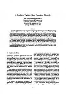
Fig. 10. Comparison of BER performance for Q(x; y ) versus q (x; y ) for two IPPM codes, ten decoder iterations.
Fig. 11. Portion of an IPPM H matrix showing sequence of shift operations, where the shaded column contains entries of the interest.
in higher throughputs. Since there are four functions computations in each MPU, the efficiency of this function has a significant effect on the final logic size of the decoder. In our example implementation (see Section V), the function constitutes 44% would increase the size of the MPU logic area. Using of each MPU by almost 50%. Simulations show that the loss of performance for our class dB at a BER of for ten of structured codes is decoder iterations. This is illustrated in Fig. 10 with reference to the codes to be described in Section V-A. 3) Compound Rotations: The revshift module on the return path of the -memory is required to reorder channel reliability values after processing by rotating them in the reverse direction to that of the shift module. Consider the highlighted column in the portion of an example matrix shown in Fig. 11, where represents a cyclic rotation by . When processing the channel values associated with this in the shift module. column, the values are first rotated by After MPU processing they are then rotated by the revshift module in the reverse direction by the same amount (which is ). The next subiteraequivalent to a forward rotation of in the tion will read the same block of data and rotate it by shift module. Note that the data values are, therefore, stored in -memory in the correct order.
2247
We can remove the revshift rotation by compounding it with the next shift module rotation. Thus, instead of a forward rotation by , the shift module performs a forward rotation of . Since all the rotation values are known in advance it is a simple matter to modify each rotation value stored in the code memory such that it accounts for the previous reverse rotation. Hence, the revshift module is no longer required. One consequence of implementing only the shift module is that the channel reliability values stored in -memory are no longer in the correct order. Therefore, when a decoding operation is complete, it is necessary to route the outgoing data through the shift module one last time, rotating the values in the reverse direction in accordance with the last rotation that was applied for that column. In the example illustrated in Fig. 11, . This final the rotation applied during this step would be rotation requires a small amount of additional logic to implement, but is significantly smaller than the logic required by the two revshift modules that have been removed. 4) Multiframe Processing: During decoding operations values are read from -memory, rotated in the shift module and processed by the MPUs. The resulting values are then written back to the same locations in -memory. In order to provide for high clock rate this datapath must be pipelined. The resulting latency means that several clock cycles elapse between reading the last value from -memory and writing the last value back. Consider the portion of a matrix shown in Fig. 11 and the resultant datapath timing in Fig. 12(a). Because the and submatrices are vertically adjacent they both operate on the same set of channel values. In addition, the subiteration involving must wait until all the channel values from the previous subiteration are written to -memory before it can start to read these values. Ultimately this means that the MPUs spend a portion of the decoding time in an idle state, thus resulting in inefficient use of the logic. This bottleneck may be removed by processing subiterations from multiple frames in an interleaved manner as illustrated in Fig. 12(b). In this case, a subiteration for frame 1 (F1) is performed, followed immediately by a subiteration for frame 2 (F2). By the time processing for the subiteration needs to begin for frame 1, the required values have already been written back to -memory for the subiteration. The MPUs are now fully utilized, thus improving efficiency and maximizing the processing throughput. A consequence of this scheme is that the -memory now requires four ports for full speed operation (left and right read ports and left and right write ports). To facilitate this a dual-port memory is run at twice the clock speed of the remainder of the decoder in order to provide the required bandwidth. Note that the same structure must be applied to the -memory in addition to the -memory. C. Decoder Summary The optimizations described in the previous section allow the implementation of a more efficient and higher throughput LDPC decoder as illustrated in Fig. 13. As with the encoder presented in Section III, all of the code information is stored in a single code memory module which act as instructions for the control sequencer module. The compact method of code storage allows the code to be changed easily on the fly or for multiple codes to be stored at once, thus facilitating rate compatibility.
2248
IEEE TRANSACTIONS ON CIRCUITS AND SYSTEMS—I: REGULAR PAPERS, VOL. 54, NO. 10, OCTOBER 2007
Fig. 12. Decoder timing for (a) suboptimal MPU usage and (b) optimal MPU usage.
Fig. 13. Optimized TDMP decoder structure.
V. IMPLEMENTATION EXAMPLE A. Structured LDPC Code Synthesis In order to demonstrate the versatility of the construction methodology described, four codes of varying rates were generated. These were the following. 1) Code A: A rate 0.33 LDPC code of length 6912. 2) Code B: A rate 0.50 LDPC code of length 6912. 3) Code C: A rate 0.66 LDPC code of length 6912. 4) Code D: A rate 0.75 LDPC code of length 6912. 108 where varied The macro-matrix in each case was depending on the code rate. In each case the scaling factor used during the expansion process was 64. The relative performance of these codes is shown in Fig. 14 for 200 decoder iterations.
Note that codes of different lengths may also be easily created by either modifying the scaling factor or using a different size for the macro-matrix. B. Encoder Implementation The encoder was implemented in VHDL and verified using the ModelSim VHDL simulator. Each of the codes generated was simulated and verified in the encoder, with the only modification to the encoder in each case being the contents of the Code RAM. Following verification, the design was targeted to a Virtex-4 part (XC4VLX25–12-FF668) using XST as a synthesis tool and ISE 7.1.03i. The design achieved a maximum clock frequency of 278 MHz. The design size was 614 slices with 11 BlockRAMs used. This equates to approximately 17-k ASIC gates).
FEWER et al.: VERSATILE VARIABLE RATE LDPC CODEC ARCHITECTURE
2249
Fig. 15. Fixed point performance curves for code B, ten decoder iterations.
Fig. 14. IPPM code performance over AWGN with varying rates, 200 decoder iterations.
TABLE II VERSATILE DECODER THROUGHPUTS
TABLE I VERSATILE ENCODER THROUGHPUTS
Throughputs for the encoder for each of the codes tested are shown in Table I.
ISE 7.1.03i. The design achieved a maximum clock frequency of 181 MHz. The design size was 10 970 slices with 46 BlockRAMs used (approximately 300 k ASIC gates). The throughputs for each of the four codes tested are shown in Table II. VI. COMPARISON WITH OTHER IMPLEMENTATIONS
C. Decoder Implementation The decoder was implemented based on the architecture shown in Fig. 13. A series of simulations was performed in order to select an optimum fixed point representation for the channel reliability values. Bit widths of 4, 5, 6, and 8 were simulated for code B with a variety of prescaling factors. The best performing quantization for each bit width is shown in Fig. 15, as well as the performance curve for floating point simulations. It is observed that curves for bit widths of 5, 6, and 8 are close together, whereas there is a significant degradation associated with the curve for the 4-bit quantization. As a result, a 5-bit representation was chosen for the decoder with a prescaling factor of 0. Thus, channel values are stored in -memory using 5 bits of precision. During processing in the MPU, the bit-growth associated with the various arithmetic operations is accommodated by increasing the bit width of the internal buses. Each of the MPUs incorporates a saturation module at its output that truncates the values back to 5 bits. The design was coded in VHDL and verified using the Modelsim VHDL simulator. A bit-accurate Matlab model was used to provide input and decoded codewords for the simulations. Each of the four IPPM codes generated in Section V-A was vervalues. ified across a range of Following verification, the design was targeted to a Virtex-4 part (XC4VLX40-12-FF668) using XST as a synthesis tool and
When comparing with other LDPC implementations in the literature, we focus only on those that provide some flexibility in terms of code rates or lengths supported. Unfortunately, many implementations are presented without logic usage and throughput metrics, making comparison difficult. In the area of encoders, Li et al. [22] presented a generalized encoding scheme based on QC-LDPC codes, which have been shown to provide good distance properties [23]. However, this implementation would appear to require significant logic resources. In addition, the density of the transformed generator matrix is likely to be quite high, ultimately requiring a complex computation process. Miles et al. [24] proposed an architecture for a specific pair of high-rate QC-LDPC codes. Although the implementation could be adapted for other codes and is hardware efficient (approximately 2500 FPGA slice equivalents for 1 Gbps throughput), application to codes of lower rate would require either a significant increase in logic usage or a corresponding decrease in throughput. As previously mentioned, Lee et al. [14] introduced a flexible encoder architecture using a serial version of the ALT encoding scheme used in this paper. However, due to the lack of structure in the code and the serial nature of the processing, the ratio of throughput to logic usage for this implementation is quite low (40 Mbps and 1340 slices for a length 4000 code). There has been more extensive work done in the area of LDPC decoders, although few of these have been very versatile.
2250
IEEE TRANSACTIONS ON CIRCUITS AND SYSTEMS—I: REGULAR PAPERS, VOL. 54, NO. 10, OCTOBER 2007
Keinle et al. [25] proposed an implementation of a decoder for the DVB-S2 standard with some background from [26]. The resulting decoder yields a high throughput (7.6 Gbps) and can accommodate several codes rates , although the code length is fixed. In addition, the implementation requires significant logic resources (approximately 4.5 million gates in 0.13 technology). Rovini et al. [27] introduced a decoder based upon the work in [28]. This implementation is very efficient and provides significant throughput (5.7-Gbps, 375-k gates). However, the codes supported are of fixed length and are quite restricted in their construction. VII. CONCLUSION In this paper, we introduced an encoder/decoder pair and code construction methodology for LDPC codes. The IPPM code synthesis scheme allows the creation of codes with a wide variety of rates and code lengths which yield good performance and low error floors. The encoder is extremely compact in terms of logic usage and is built around a central high-speed processing engine that allows high levels of throughput across a variety of code rates. The decoder exhibits the high-speed convergence and logic scalability of a TDMP decoder and includes a series of optimizations that have been made to take advantage of the structured IPPM codes that have been developed. Most significantly these implementations allow dynamic switching between any codes in the IPPM class. Although implementations of most encoders and decoders typically excel with respect to throughput, logic efficiency or code performance, few can be said to provide an efficient balance of all of these. The work presented in this paper attempts to do just that, while yielding a level of versatility that permits the use of a wide range of code lengths and rates. The assembled system (code, encoder, and decoder) allows a practical versatile variable rate LDPC system to be built without the performance degradation seen in puncture-based systems. REFERENCES [1] R. Gallager, “Low-density parity-check codes,” IEEE Trans. Inf. Theory, vol. IT-8, no. 1, pp. 21–28, Jan. 1962. [2] D. MacKay and R. Neal, “Good codes based on very sparse matrices,” presented at the IMA Conf. Cryptography and Coding, 1995. [3] D. MacKay, “Good error correcting codes based on very sparse matrices,” IEEE Trans. Inf. Theory, vol. 45, no. 2, pp. 399–431, Mar. 1999. [4] N. Alon and M. Luby, “A linear time erasure-resiliant code with nearly optimal recovery,” IEEE Trans. Inf. Theory, vol. 42, no. 6, pp. 1732–1736, Nov. 1996. [5] T. J. Richarson, M. A. Shokrollahi, and R. L. Urbanke, “Design of capacity-approaching irregular low-density parity-check codes,” IEEE Trans. Inf. Theory, vol. 47, no. 2, pp. 619–637, Feb. 2001. [6] T. J. Richarson and R. L. Urbanke, “The capacity of low-density parity-check codes under message-passing decoding,” IEEE Trans. Inf. Theory, vol. 47, no. 2, pp. 599–618, Feb. 2001. [7] S. Chung, G. Forney, T. Richardson, and R. Urbanke, “On the design of low-density parity-check codes within 0.0045 db of the Shannon limit,” IEEE Commun. Lett., vol. 5, no. 2, pp. 58–60, Feb. 2001. [8] A. Blanksby and C. Howland, “A 690-mW 1-Gb/s 1024-b, rate-1/2 low-density parity-check code decoder,” IEEE J. Solid-State Circuits, vol. 37, no. 3, pp. 404–412, Mar. 2002. [9] J. K. Lee, B. Lee, J. Thorpe, K. Andrews, S. Dolinar, and J. Hamkins, “A scalable architecture of a structured LDPC decoder,” in Proc. Int. Symp. Inf. Theory, 2004, p. 292.
[10] D. E. Hocevar, “LDPC code construction with flexible hardware implementation,” in Proc. Int. Conf. Communications, May 2003, pp. 2801–2712. [11] M. Mansour and N. Shanbhag, “High throughput LDPC decoders,” IEEE Trans. Very Large Scale Integr. Syst., vol. 11, no. 6, pp. 976–996, Dec. 2003. [12] H. Zhong and T. Zhang, “Block LDPC: A practical LDPC coding system design approach,” IEEE Trans. Circuits Syst., vol. 52, no. 4, pp. 766–775, Apr. 2005. [13] T. J. Richarson and R. L. Urbanke, “Efficient encoding of low-density parity-check codes,” IEEE Trans. Inf. Theory, vol. 47, no. 2, pp. 638–656, Feb. 2001. [14] D. Lee, W. Luk, C. Wang, C. Jones, M. Smith, and J. Villasenor, “Low-density parity-check code constructions for hardware implementation,” in Proc. IEEE Symp. Field-Programmable Custom Computing Machines, 2004, pp. 101–111. [15] L. Sun and B. V. K. V. Kumar, “Field programmable gate array implementation of a generalized decoder for structured low-density parity check codes,” in Proc. IEEE Int. Conf. Field-Programmable Technology, 2004, pp. 17–24. [16] D. Sridhara, T. Fuja, and R. M. Tanner, “Low density parity check codes from permutation matrices,” presented at the John Hopkins Conf. Information Sciences and Systems, 2001. [17] S. Myung, K. Yang, and J. Kim, “Quasi-cyclic LDPC codes for fast encoding,” IEEE Trans. Inf. Theory, vol. 51, no. 8, pp. 2894–2901, Aug. 2005. [18] R. L. Urbanke, LDPCOpt—A Tool for Determination of Optimal Degree Distributions. [Online]. Available: http://lthcwww.epfl.ch/research/index.php [19] T. Tian, C. Jones, J. D. Villasenor, and R. D. Wesel, “Construction of irregular LDPC codes with low error floors,” in Proc. IEEE Int. Conf. Communications, May 2003, pp. 3125–3129. [20] J. Kang and P. Fan, “Flexible construction of irregular partitioned permutation LDPC codes with low error floors,” IEEE Commun. Lett., vol. 9, no. 6, pp. 534–536, Jun. 2005. [21] M. Mansour and N. Shanbhag, “A novel design methodology for highperformance programmable decoder cores for AA-LDPC codes,” in Proc. IEEE Workshop on Signal Process. Syst., Aug. 2003, pp. 29–34. [22] Z. Li, L. Chen, L. Zeng, S. Lin, and W. Fong, “Efficient encoding of quasi-cyclic low-density parity-check codes,” in Proc. IEEE Globecom, 2005, pp. 1205–1210. [23] Y. Kou, S. Lin, and M. P. Fossorier, “Low-density parity-check codes based on finite geometries: A rediscovery and new results,” IEEE Trans. Inf. Theory, vol. 47, no. 11, pp. 2711–2736, Nov. 2001. [24] L. Miles, J. Gambles, G. Maki, W. Ryan, and S. Whitaker, “An (8158,7136) low-density parity-check encoder,” in Proc. IEEE Conf. Custom Integr. Circuits, 2005, pp. 699–702. [25] F. Keinle, T. Brack, and N. Wehn, “A synthesizable IP core for DVB-S2 LDPC code decoding,” in Proc. Eur. Conf. Design, Autom. Test, 2005, pp. 100–105. [26] F. Keinle and N. Wehn, “Design methodology for IRA codes,” in Proc. ASP Des. Autom. Conf., 2004, pp. 459–462. [27] M. Rovini, N. E. L’Insalata, F. Rossi, and L. Fanucci, “VLSI design of a high-throughput multi-rate decoder for structured LDPC codes,” in Proc. 8th Euromicro Conf. Digital Syst. Des., 2005, pp. 202–209. [28] H. Zhong and T. Zhang, “Joint code-encoder-decoder design for LDPC coding system VLSI implementation,” in Proc. IEEE Int. Symp. Circuits and Systems, May 2004, vol. 2, pp. 389–392. [29] J. Ha, J. Kim, and S. McLaughlin, “Rate-compatible puncturing of lowdensity parity-check codes,” IEEE Trans. Inf. Theory, vol. 50, no. 11, pp. 2824–2836, Nov. 2004.
Colm P. Fewer recieived the B.E. degree in electronic engineering and the M.Sc.Eng. degree from the University College Dublin, Dublin, Ireland, in 1996 and 2006, respectively. From 1996 to 2000, he was with Parthus Technologies developing advanced storage devices. From 2000 to 2005, he was with Xilinx, Inc., implementing high-speed digital designs in the design services division. He is currently with Acra Control, Ltd., developing point-to-point radio links for the aviation industry. His research interests include forward-error correction with an emphasis on LDPC codes, in addition to cryptography and coded modulation for wireline and wirelss communications.
FEWER et al.: VERSATILE VARIABLE RATE LDPC CODEC ARCHITECTURE
Mark F. Flanagan received the Ph.D. degree in electronic and electrical Engineering from University College Dublin (UCD), Dublin, Ireland, in 2005. From April 2005 until March 2007, he was a Postdoctoral Researcher with the Digital Signal Processing Research Group at UCD. He is now a Postdoctoral Researcher with the Claude Shannon Institute for Discrete Mathematics, Coding, and Cryptography. His research interests include the design of iterative receivers, algebraic constructions of LDPC codes, and coded modulation for wireline and wireless communication systems.
2251
Anthony D. Fagan received the Ph.D. degree from the University College Dublin (UCD), Dublin, Ireland, in 1978. He was a Research Engineer at Marconi Research Laboratories, Essex, from 1977 to 1980, where he worked on digital signal processing (DSP) for advanced communication systems. In 1980, he became a Lecturer in the Department of Electronic and Electrical Engineering, UCD, where he established the DSP Research Group. The group carries out a balanced mix of theoretical and applied research in the areas of digital communications (wireline and wireless), speech and audio processing, image processing, pattern recognition, and biomedical signal processing. He is a member of the editorial board of Digital Signal Processing, as well as a reviewer for many international journals. He frequently acts as a reviewer of projects and an evaluator of proposals for the European Commission. He has been instrumental in the establishment of a number of Irish companies that carry out work at the highest level in the area of physical layer communications, and he is widely consulted by many international communication companies. His main research interest is in the application of DSP techniques to advanced digital fixed-line and wireless communications, with a particular interest in synchronization techniques, adaptive modulation, equalization, detection methods, and flexible use of the radio spectrum. He also has research interests in the areas of speech, audio, and image processing.