411
A Visual Approach To Geometric Programming Franco Milicchio, Alberto Paoluzzi and Claudio Bertoli Università Roma Tre
[email protected],
[email protected],
[email protected]
ABSTRACT In this paper we introduce a visual approach to functional programming with PLaSM, a design language used for geometric programming and the parametric generation of CAD models. A visual diagram is generated according to very few simple rules, and may be used both for automatically generating the corresponding PLaSM code and for the specification and distribution of computer tasks to be concurrently run in a multithread environment, either single or multi-host. The visual diagram of a computation may be used as a tool to make the code debugging easier and interactive, since it allows for inspecting each value in the functional environment with a single point-and-click interaction paradigm, as well as a user-interface to powerful generative CAD environments. Keywords: Visual Language, Geometric Programming, Computer-Aided Software Engineering
1. INTRODUCTION In order to develop parametric CAD applications to be used for training, analysis, manufacturing or gaming, a development of geometric models by using some programming language is quite always needed. Two main options are available, corresponding to either using libraries of geometric classes embedded into C/C++ (less frequently Java) or using specialized data languages based on XML. In order to develop in the first framework, expert programmers are needed who are skilled both in object-oriented programming and in 3D graphics (as an example consider the CAAV5 application framework by Dassault Systémes). In the second approach, authoring tools exist to support the user through graphical interfaces connected to the CAD system. Both the approaches have drawbacks that limit their diffusion among interested but non-expert users (students, architects, product engineers and designers, etc.). In particular, object-oriented techniques are quite difficult for the final users, i.e. the expert of the application field, who is not required to be a professional programmer and has no specific programming interest or training. The authoring approach offers every user simple interactive tools that everybody can easily learn to use. However, these tools lack the power for generating full-featured and detailed models of very complex assemblies. Even worst, since they produce data files based on quite simple description languages, it is pretty hard to reuse or update previously developed models, even when a closed proprietary format is not used. Conversely, the design language PLaSM [10, 7, 6], a geometric extension of Backus FL [1], provides the full power of a programming language (with support for conditional, recursion, higher-level functional abstraction, etc.) while being geometry-oriented, with dimension-independent geometric primitives and operators, allowing very terse definitions of highly complex models. The generated objects and assemblies can then be exported in several formats and rendered by a VRML browser or imported into Java3D applications. The main goal of this paper is to discuss the design of a visual approach to geometric programming with PLaSM. To provide a geometric language with a visual programming interface may strongly ease, and mostly automate, the development and debugging of complex, reusable and geometrically accurate parts and assemblies. The use of visual aids in the programming world at-large was often successful. Many specialized visual languages have been proposed for very different applications, such as DOODLE [3] for OO databases and Datavis [5] for scientific visualization. All of these visual languages carry with them the complexity of the symbolic languages they express. In the following sections, the paper will introduce the main ideas about parsing and syntax of a visual notation that is equivalent to the textual PLaSM language. Such a notation will allow the expert user to better understand, optimize and debug a PLaSM source script, and will give the novice user a simple and easy-to-use tool to generate geometric models and assemblies of high complexity. The prototype implementation of the visual language here discussed was
Computer-Aided Design & Applications, Vol. 2, Nos. 1-4, 2005, pp 411-419
412
built to enforce a strong interface minimalism, relying only on two graphical tokens (for data and programs, respectively) and on the functional abstraction, i.e. the association of a symbol to an arbitrary subexpression. 2. VISUAL PLASM Generally speaking, each PLaSM program is a function. When applied to some input argument, a program produces some output value. Two programs are usually connected by using functional composition, so that the output of the first program is used as input to the second program, as shown in Fig. 1. An even brief introduction of the PLaSM syntax is beyond the goals of this paper. Let us just remember that , where x1, ..., xn are arbitrary expressions, is a sequence, and that language operators are normally prefix to the argument, and applied to it by using the infix application operator “:”. 2.1 Visual paradigms According to the FL semantics, an arbitrary PLaSM script can be written by using only three programming constructs: 1. application of a function to the actual value of its input parameters, elements of the function domain, producing the corresponding output value in the function codomain; 2. composition of two or more functions allowing the pipelined execution of their ordered sequence; 3. construction of a vector function allowing the parallel execution of its component functions; 2.1.1 Model of computation A computation is considered here as a primitive concept, and corresponds to the execution of a set of computer processes finalized to the generation of a value of arbitrary type. The visual model of a computation is a directed graph G = (N, A) where the set N of nodes is partitioned in two disjoint subsets Np of programs objects and Nd of data objects. The set A of directed arcs is partitioned into three disjoint subsets, Aa ⊂ Nd × Np, Ac ⊂ Np × Np and Ae ⊂ Np × N, corresponding to the binary relationships of application, composition and evaluation, respectively. There is no semantic difference between data and programs. A datum in a given computation can be a program in another computation. The nodes in Nd will be visually represented as rounded boxes, those in Np as squared boxes. The application of the program node ni on the data node nk is represented by the directed arc (ni, nk), and is normally drawn in the diagram of the computation as a vertical segment, where nk is displayed above ni.
Fig. 1. (a) A function (program) can be visualized as a black box, i.e. an unknown transformation between input and output values (b) the application of a function to x may produce either a data object or a program object (c) a function composition is a computational pipeline where the input data flow through, being subject to successive transformations, until to generate the output value.
It is very easy to recognize the relationship an arc belongs to. A vertical arc between two nodes in Np stands for
composition; a vertical arc below a node in Nd stands for application; vertical arcs above a node in Nd and horizontal arcs stand for evaluation. Computer-Aided Design & Applications, Vol. 2, Nos. 1-4, 2005, pp 411-419
413
A function is a black box. box Our first representational paradigm is concerned with abstracting a program behavior as a black box, that represents the transformation between input and output data, as shown by Fig. 1a. The standard behavior of a function is to accept a single input value and to produce a single output value. Multiple values are managed as a single value of sequence type. Application is a binary relationship. As we already said, the application of the program object f to the data object x can be represented in the visual diagram as the arc (x, f) ∈ Aa ⊂ Nd × Np, and that will be drawn between the nodes associated to x and f, respectively. The evaluation of the triple (x, (x, f), f) produces the output f(x), that can be either a data object or a program object. The two cases are graphically distinguished by the direction of the arc (f, f(x)) leaving the f node, that is drawn either horizontally or vertically, according to Fig. 1. Composition is pipelining. According to the mathematical definition of function composition: (f ˚ g) (x) ≡ f (g(x)) requiring the function f to be applied to the value resulting from the g application to the x value, our second representational paradigm, graphically represented in Fig. 1c, states that a function composition is a computational pipeline working in the reverse order of the functions to be composed. Partial functions. In PLaSM a higher-order curried function of the kind: f : A → B → C ≡ A → (B → C) can be defined, using formal parameters, as: DEF f (a::isA)(b::isB) = body_expr; where isA and isB are predicates used to test at run-time the set-membership of actual arguments. The function f is applied to arguments as f:x:y ≡ (f:x):y, returning – since application is left associative – a value c ∈ C. Also, notice that the value generated by evaluating the expression f:x is a partial function. Partial functions as λ-functions. A global function head may contain zero, one or more parameter lists. Correspondingly, the function is invoked with zero, one or more applications to actual arguments. The presence of more than one parameter list is allowed to permit the specification of partial functions. A function with n parameter lists is called a function of n-th order. Such a function, when applied to actual arguments for the first parameter list, returns a function of order (n - 1). This one, when further applied to actual arguments for the second parameter list, returns a function of order (n - 2), and so on. Finally, when all the parameter lists are bound to actual arguments, the function returns the value generated by the evaluation of its body. Functions of order higher than one are called higher-order functions. The functions returned from the application of higher-order functions to some (ordered) subset of their parameter lists are called partial functions. As shown in Fig. 2, a partial application of a function of second order (or more), generates an anonymous function, drawn as an unnamed box, which needs additional inputs. These particular kind of functions are known in the Lisp world as λ-functions: well defined functions with no name.
Fig. 2. (a) Typical pattern of evaluation of partial functions, depending on the number of actual parameters supplied; (b) evaluation model of a vector function, based on the second-order CONS (construction) combinator, that may produce the parallel computation of various threads.
Computer-Aided Design & Applications, Vol. 2, Nos. 1-4, 2005, pp 411-419
414
Conditional combinatory. The conditional form IF::x has the following semantic: “IF the predicate p applied to x is true, THEN apply f to x; ELSE apply g to x”. This construct is very useful when it is necessary to apply different actions to input data depending on the value of some predicate evaluated on them, and is probably more “natural” than the conditional statements available in other languages. From a syntactical viewpoint, the IF operator is a higher-order function that must be applied to a triplet of functions in order to return a λ-function which is in turn applied to the input x. Let us compare the diagram of Fig. 3 with the standard conditional diagram of structured programming. Notice that this one would not work as a data-flow diagram; conversely, the diagram of Fig. 3, that is built according to our visual programming paradigm, is a working visual program that can be parsed and executed automatically.
Fig. 3. The data-flow diagram of the conditional operator. Notice that the conditional diagram of structured programming would not work as a data-flow.
Values and sequences. A data object may denote either a single value or a sequence of values. In both cases the rounded box is used to contain the single or multiple generating expression(s), without confusion. As a matter of fact, if some commas appears in the symbolic string contained in the box, then this one necessarily hosts a sequence; otherways it contains a value. The only exception is constituted by the single element sequence. Only in this case the generating expression of the value must be enclosed between angled parenthesis. Abstraction and information hiding. In imperative programming, abstraction stands for the process of picking out (abstracting) common features of objects and procedures. A simpler meaning is given to abstraction in (pure) functional programming, i.e. to associate a symbol, or in other words, to assign a name to an arbitrary expression. Information hiding is the process of hiding details of an object or function. Information hiding is a powerful programming technique because it reduces complexity. One of the chief mechanisms for hiding information is encapsulation, combining elements to create a new entity. For example, a procedure is a type of encapsulation because it combines a series of computer instructions. Likewise, a complex data type, such as a record or class, relies on encapsulation. The programmer can then focus on the new object without worrying about the hidden details. Visual abstraction and encapsulation. In visual PLaSM the encapsulation and information hiding are always associated with abstraction. In particular, any arbitrary connected portion of a visual diagram can be selected with some proper selection tool. The corresponding diagram can be contracted to a single named node, subject to the reduction rules discussed below, that depend on the type and number of edges crossed by the boundary of the selected area. In particular, any PLaSM definition may contain a local environment, expressed by the WHERE-END block, specifying local definitions whose bodies can encapsulate other local environments. This structure leads to a nested definition tree, where nodes denote local definitions, and at each nested level a new environment is generated within the context of the local environment. Let us remember that in functional languages an environment is a set of pairs (symbol, value). 2.2 Examples Curried equality . The comparison predicate EQ is normally used as a binary predicate, i.e. is normally applied to a pair of arguments – actually, it can be applied to any n-tuple of arguments, with n ≥ 1. It can sometimes be very useful to have a partial function to test the equality of a variable argument with a fixed one. This test could be done, e.g., by using the curried function C:EQ.
Computer-Aided Design & Applications, Vol. 2, Nos. 1-4, 2005, pp 411-419
415
Fig. 4. Three equivalent expansions of the test predicate.
Predecessor. A predecessor function pred : N → N such that n → n – 1 can be easily defined in PLaSM as the curried addition with the -1 value, i.e. DEF pred = C:+:-1; Clearly, for such a definition three possible visual diagrams hold, corresponding to the same expansions given in Fig. 4 for the test function.
Fig. 5. Two applications of the test function to a data value.
2.3.1 Euler number The Euler number e is defined as the sum of the series of reciprocal of factorial numbers. In formal terms:
e=
1 1 1 1 + + + ... + + ... 0! 1! 2! n!
We compute an approximation of e, named euler, as the sum of the first 30 terms of the series above. Notice that the + operator may be applied to a sequence of numeric arguments and remember that 0! = 1. DEF f = C:/:1.0 ~ fact; DEF euler = (+ ~ AA:f):(0..9); We notice that the curried division with parameter 1 just produces the reciprocal of its input, so that we have
f :n ≡
1 n!
The visual program corresponding to the above PLaSM code is shown in Fig. 6, using a top-down style, where we orderly give: 1. the code pattern, that can be used for evaluating the approximate sum of an arbitrary series, provided that the input function f specifies the generator of the series elements; 2. a specification of the code with bound f; 3. the block-decomposition of the f function, that is applied to each element of the input series;
Computer-Aided Design & Applications, Vol. 2, Nos. 1-4, 2005, pp 411-419
416
Fig. 6. Computation of the Euler number: (a) program pattern with variable f; (b) specification of the e computation; (c) expansion of the f function.
3. APPLICATIONS Applications of such a framework are straightforward. In first place, a functional data-flow diagram is easily understandable by a naïf user, and does not require a deep knowledge of the programming language. Drawings are easier to understand for an human than textual coding, as the increasing usage of icons and visual representations is showing every day. It is a fact that two boxes connected by a line are more understandable than the corresponding string f ~ g. As we have said in the introduction, we aim to enforce a minimalism constraint for the discussed visual language. For this purpose, the visual approach proposed in this paper allows only two visual tokens, i.e. a squared box and a rounded box, representing respectively functions and data. Each token is not necessarily a primitive one, as we have seen in the previous section. For example, an input datum can be either a user-defined expression or sequence of expressions, or the single value resulting from a computation of arbitrary complexity over some input data set. Automatic scheduling of tasks. It has been shown in the previous sections that PLaSM is mainly based on the composition of functions. This paradigm makes it easy for an interpreter to manage arbitrary computations over simultaneous tasks. Let us consider separately each point of a possible parallel execution. It is clear that the CONS function allows for the parallel execution of its functional arguments, being these functions over the same domain. In fact the CONS constructs a vector function whose components are separately applied to a given data set, producing the sequence resulting from the evaluation of the applied functions. In this case, the simultaneous application of each component of the vector function is possible and safe, since no side effect can be produced. A sort of “dual” operator of the CONS is the apply-to-all function AA. The application of the second-order AA operator to a function f and then to a sequence < xi > of arguments leads to the generation of an output sequence < f:xi >. Again, the parallel execution of this task has no side effects and can be done safely. Furthermore, since this functional language is pure, i.e. without assignment and hence with no side effects, the expressions within an arbitrary sequence can always be safely computed in parallel. At present time, the PLaSM geometric kernel is under a complete re-implementation. As this task is finished, PLaSM will support an automatic scheduling and distribution of tasks, underlying a new progressive BSP-based geometric kernel [9]. In this framework the computation of complex models results in a tree of pipelined processes that concurrently calculate the result continuously, so that coarse approximations of the final results are given nearly instantly, and more details are obtained as the computation goes on, making it possible to have generative operations, as well as the visualization of the results, in a parallel environment. High-level interface to PLM environments. The visual interface for geometric programming dissussed here is part of a SUR Project awarded in late 2003 by IBM with an equipment donation to Roma Tre for a new lab of Intelligent Computational Design, where to pursue the representation and handling of design knowledge through a powerful design language, as well as the study of new approaches to the integration of geometric modeling and computational physics in a strongly distributed environment for physically-based design. Most CAD systems have an extension language based either on Scheme or on Common Lisp, or even on Visual Basic. We aim to provide Catia with a functional extension based on PLaSM, since we believe it could provide an amazing power in dealing symbolically with geometric objects and knowledge. A deliverable of this project is a specialized IDE
Computer-Aided Design & Applications, Vol. 2, Nos. 1-4, 2005, pp 411-419
417
for the PLM application programmer or user, offering specialized plug-ins for the Eclipse platform, including a PLaSM Visual Editor, a parallel dispatcher, an OpenGL progressive viewer, and an interface to Catia. In collaboration with L. Livermore National Labs (V. Pascucci) we are implementing new methods for progressive realtime refinement, combination and visualization of very complex geometric shapes and assemblies, based on data-flow architectures, where distributed BSP-based software components generate, transform, combine, simulate or observe suitable atomic data structures, depending on the task they have to perform. This project may have some interest also from an architectural viewpoint, since a monolithic kernel is substituted by a set of pipelined and distributed processes, producing more and more detailed representation of a geometric object, depending on the available computational resources (time, processors, memory, bandwidth). The integration of techniques from combinatorial topology with progressive BSP trees constitutes the goal of the last sub-project, which hinges on the collaboration with the Spatial Automation Lab of the University of Wisconsin at Madison (V. Shapiro) and SMFM (Mathematical Structures of Materials Physics) at “Roma Tre” (A. DiCarlo). To this purpose a research direction is being explored, allowing for combined design and manipulation of both geometrical shape and physical behavior. 4. PROGRAMMING EXAMPLE 4.1 Wing profile design The creation of surfaces smoothly connecting two given curves with assigned derivative fields by cubic transfinite blending is discussed in this section. A transfinite CubicHermite mapping is given, according to the dimensionindependent character of PLaSM implementations of transfinite methods, with four data objects given as formal parameters. Such data objects may be either points/vectors, i.e. sequences of numbers, or 1/2/3/d-variate maps, i.e. sequences of (curve/surface/solid/etc.) component maps, or even mixed sequences, as shown in [8]. For a full understanding of the following code, where a polynomial basis is generated by algebraic operations on R → R maps, the reader is referred to [7]. DEF HermiteBasis (u:isFun) = < h0, h1, h2, h3 > WHERE h0 = k:2 * u3 – k:3 * u2 + k:1, h1 = k:3 * u2 – k:2 * u3, h2 = u3 – k:2 * u2 + u, h3 = u3 – u2, u2 = u * u, u3 = u * u * u, fun = (AA ~ AA):(IF:) END; DEF TransfiniteHermite (u::isFun)(p1, p2::isPoint)(t1, t2::IsVect) = (AA:InnerProd ~ DISTL):; The curve maps c1(u) and c2(u) generated by two points and two tangent vectors in 3D are interpolated the transfinite TheSurface mapping using the cubic Hermite basis η3 = (η3j), 0 ≤ j ≤ 3, with the further constraints that the tangent vector field TheSurfacev(u, 0) along the first curve are constant and parallel to (0, 0, 100), whereas TheSurfacev(u, v) along the second curve is also constant and parallel to (0, 0, -100). The resulting map has unique vector representation in P33[P3] as TheSurface = c1 η30 + c2 η31 + (κ(0), κ(0), κ(100)) η32 + (κ(0), κ(0), κ(-100)) η33 Where the η3i, 0 ≤ i ≤ 3, are the cubic Hermite basis of polynomials, and κ(x), x ∈ R, are constant maps R → R. Such a map is very easily implemented by the visual PLaSM definition given in Fig. 9. A simplicial approximation of the point set TheSurface([0, 1]2) is generated by the MAP diagram shown in Fig. 8.
Computer-Aided Design & Applications, Vol. 2, Nos. 1-4, 2005, pp 411-419
418
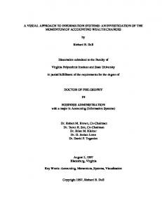
Fig. 7. The VRML model of the wing surface generated by the output visual expression shown in Fig. 9
5. CONCLUSION A visual approach to geometric programming and computing was discussed in this paper. The proposed visual PLaSM language is an extremely simple implementation of the data-flow paradigm in a pure functional sense, and still powerful as the textual sibling. The visual environment for PLaSM programming discussed in this paper is currently under development in the Eclipse environment and with the Qt Library, and only a preliminary (but well working) prototype was already produced. We intend to use the visual environment and the associated diagram compiler not only as a programming and debugging tool, but also as a scheduler for a parallel execution. A new progressive geometric kernel is in fact being developed, allowing continuous generation and streaming of geometric models at progressive levels of detail. We believe that coupling the visual and functional paradigms, with automatic detailing and streaming of geometry along a tree of pipelined data-flow processes, will be provably very useful to cope with the generation of complex assemblies with increasing requirements of data quality and size.
Fig. 8. (a) The VisualPLaSM prototype user interface. The expression trees of the open functions are on the left pane; the visual diagram of the body of the current function is on the right pane; the listener on the bottom pane.
Computer-Aided Design & Applications, Vol. 2, Nos. 1-4, 2005, pp 411-419
419
Fig. 9. (a) The complete executable dataflow code of the wing example. The only library function used is HermiteBasis:u that returns the cubic Hermite basis polynomials, whose textual code is given above.
6. REFERENCES [1] Backus, J., Williams, J., and Wimmers E. An introduction to the programming language FL. In Research Topics In Functional Programming, D. Turner, Ed. Addison-Wesley, Reading, Massachusetts, 1990, ch. 9, pp. 219247. [2] Costagliola, G., Deufemia, V., Ferrucci, F., and Gravino C. Using extended positional grammars to develop visual modeling languages. In Proceedings of the 14th international conference on Software engineering and Knowledge engineering (2002), ACM Press, pp. 201-208. [3] Cruz I.F. Doodle: a visual language for object-oriented databases. In Proceedings of the 1992 ACM SIGMOD international conference on Management of data (1992), ACM Press, pp. 71-80. [4] Davis A. L., and Keller R. M. Dataflow program graphs. IEEE Computer 15, 2 (1982), 26-41. [5] Hils D. D. Datavis: a visual programming language for scientific visualization. In Proceedings of the 19th annual conference on Computer Science (1991), ACM Press, pp. 439-448. http://www.plasm.net. [6] [7] Paoluzzi A. Geometric Programming for Computer Aided Design. John Wiley & Sons, Chichester, UK, 2003. [8] Paoluzzi A. Variable-free representation of manifolds via transfinite blending with a functional language, Mathematics of Surfaces, Wilson, Michael J.; Martin, Ralph R. (Eds.) Springer-Verlag, Lecture Notes in Computer Science, Vol. 2768, 2003. [9] Paoluzzi A., Pascucci V., and Scorzelli G. Progressive dimension-independent boolean operations. In Proceeding of the 9-th ACM Symposium on Solid Modeling and Applications (2004), G. Elber, N. Patrikalakis, and P.Brunet, Eds., pp. 203-212. [10] Paoluzzi A., Pascucci, V., and Vicentino M. Geometric programming: a programming approach to geometric design. ACM Transactions on Graphics 14, 3 (July 1995), 266-306.
Computer-Aided Design & Applications, Vol. 2, Nos. 1-4, 2005, pp 411-419