See-Through Vision: A Visual Augmentation Method for Sensing-Web Yuichi Ohta, Yoshinari Kameda, Itaru Kitahara, Masayuki Hayashi, and Shinya Yamazaki Department of Intelligent Interaction Technologies, University of Tsukuba Tennoudai 1-1-1, Tsukuba Science City, Ibaraki, Japan {ohta,kameda,kitahara}@iit.tsukuba.ac.jp,
[email protected]
Abstract. Many surveillance cameras are being installed throughout the environments of our daily lives because they effectively maintain safety and offer security to ordinary people. On the other hand, they can also cause serious discomfort and anxiety to the same people. This paper proposes a novel framework called See-Through Vision that utilizes surveillance cameras as a public sensing device by exploiting a state-of-the-art mixed-reality technique. Some advanced systems developed by us for See-Through Vision are introduced, and we discuss their advantages and how they actually maximize the benefits of surveillance cameras. Since See-Through Vision is a powerful tool that may violate the privacy of other people, we propose a sophisticated solution that can strike a good balance between the benefits and the drawbacks of such an approach. We propose privacy-safe See-Through Vision and demonstrate the system at a shopping mall in Kyoto. Keywords: Sensing-Web, Outdoor Mixed-Reality, Visual Augmentation, Privacy Control.
1 Introduction With increasing concerns about security, surveillance cameras continue to be ubiquitously installed in public places. When installing a surveillance camera, it is important to build a social consensus that reaches a good compromise between the security of the public space and the comfort of the monitored people. Although one crucial role of surveillance cameras is maintaining security, this benefit is not easily recognized since safety is invisible and access to such systems is not provided to the public. We are enhancing video surveillance systems with the additional role of letting people visually and intuitively understand the benefits of surveillance cameras. This paper introduces our visual augmentation methods for surveillance cameras to carry out the above approach by utilizing a mixed-reality (MR) technique. Users can see and use extra visual information that is captured by surveillance cameras, appropriately transformed in MR fashion, and superimposed by an MR technique onto their view through their mobile display devices such as personal digital assistants (PDAs) or cell phones. E. Hüllermeier, R. Kruse, and F. Hoffmann (Eds.): IPMU 2010, Part II, CCIS 81, pp. 690–699, 2010. © Springer-Verlag Berlin Heidelberg 2010
See-Through Vision: A Visual Augmentation Method for Sensing-Web
691
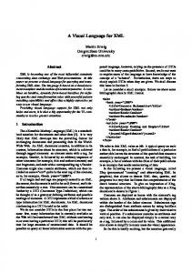
Fig. 1. Concept of See-Through Vision
We have been developing a See-Through Vision system [1] that allows users to observe such hidden areas as the blind corners of buildings (Fig. 1). It also helps people who might be the subject of surveillance cameras to easily understand the contents of the visual information and the properties of the capturing camera (e.g., resolution, field of view, and capturing angle) and thus decrease their level of discomfort.
2 See-Through Vision A see-through display is implemented using surveillance cameras installed in public outdoor spaces. By calibrating surveillance cameras beforehand and calibrating a handheld device’s camera on-line, objects in a hidden area can be displayed on the handheld device in MR style. Although it is easy to estimate the pose of a handheld device’s camera if artificial markers are available, there are few outdoor scenes where specially designed calibration markers such as checkerboards can be installed. Therefore, we propose a method to estimate the pose of the handheld device’s camera without using artificial markers. Instead, we use the substructures of buildings as calibration markers. Usually, the shapes of substructures (called landmarks) can be obtained from CAD data of the building or the scene. One of the critical problems of this approach is that the appearance of a landmark changes widely while the handheld device is moving. The major reasons for such appearance change are changes in light conditions, color fading, aging, etc. These phenomena cannot be prevented, even if relatively large and substantial parts of the buildings in a scene are set as landmarks. Therefore, we extract the live textures of landmarks from the videos of surveillance cameras to follow their texture changes. 2.1 Camera Registration Our handheld device is equipped with a GPS, a digital compass, an inertia sensor, and a color video camera. The GPS and digital compass obtain the initial estimation of location and the orientation of the handheld device. The inertia sensor can track the pose change of the handheld device at high frequency. However, it is not adequate for precisely superimposing 3D CG models and live video onto the handheld device’s camera images due to their problems of long-term instability such as drift.
692
Y. Ohta et al.
Fig. 2. Visualizing hidden areas; a rectangle on a wall becomes visible
We define landmarks in the outdoor scenes and use them as embedded natural markers. To accurately define the landmarks for image processing, they must be distinct in the scene. We adopt the substructures of buildings with good features for tracking [2] when they are captured on the handheld device’s camera image. Choosing these substructures reduces the chance of false extraction in image processing. Each landmark has geometric information given by the CAD and/or CG data and pictorial information obtained with a surveillance camera in real time. The best surveillance camera, which actually takes pictorial information of a landmark, is selected based on the location relationship of the handheld device’s camera, the landmark, and the surveillance camera. 2.2 Visualizing Hidden Areas To visualize objects in hidden areas, we use a simple yet effective rectangle-based video warping method. Rectangles are set perpendicular to the ground in the hidden areas. Corresponding video segments are transmitted from an appropriate surveillance camera capturing the area to the handheld device, and the segments are warped based on the projection matrices given by the calibration results. Figure 2 shows an example of the visualization. In this case, a rectangle is set on the wall of a building adjacent to the hidden area. The system holds the geometric 3D points of the rectangle (g0…g3) and the corresponding 2D points (c0…c3) in the live video frame taken by the most appropriate surveillance camera. With these corresponding points, a homography matrix can be calculated to project the captured live video segment onto an image shown on the handheld device’s display.
3 Advanced See-Through Vision With basic See-Through Vision as described in the previous section, users can only observe a hidden area occluded by a building in front of them. On the other hand, if more surveillance cameras were installed here and there, richer visual information of a target scene would be available. In this section, we introduce our two types of
See-Through Vision: A Visual Augmentation Method for Sensing-Web
693
advanced See-Through Vision systems designed with new functions that allow users to utilize visual information captured over a wider area. 3.1 See-Through Vision in Wider Areas The virtual viewpoint motion shown in Fig. 3 is a novel interface for improving the visibility of hidden areas. Users can virtually get close to their desired area and see objects there in high resolution [3]. Since the virtual viewpoint can go through buildings, users can clearly see even objects that are in distant blind areas hidden by blindfolds such as buildings.
Fig. 3. See-Through Vision in Wide Area
3D Model of Background Region 3D information is necessary to generate a view from an arbitrary viewpoint. We acquire the 3D shapes of such static background regions as roads and buildings in advance. The texture is updated online by mapping segments of images captured by surveillance cameras while referring to the projective matrix of the surveillance cameras. 3D Model of Foreground Objects The foreground objects are modeled by the billboard technique [4] with live texture captured by surveillance cameras. The object’s billboard is put at a position estimated from the image of surveillance cameras. Generally speaking, at least two cameras are necessary to estimate the 3D position of an object in a scene. However, surveillance cameras usually do not have overlapping areas among the cameras; consequently, we could not apply this method to our problem. Our system estimates the 3D positions of foreground objects using only a single camera while assuming that all of the objects stand perpendicular to the ground plane. Here, a foreground object is modeled by a rectangular polygon called a billboard (Fig. 4). By defining the billboard with a planner bounding box that encompasses the object, we can know the diagonal corners X lb and X ru of the billboard in 3D space. We
694
Y. Ohta et al.
assume that the height difference of X lb and X ru is the height of human beings, or h. Since the camera has already been calibrated, we can find the corresponding 2D points U lb and U ru in the camera image. By cutting out the image segment between U lb and
U ru and then by projecting the cut segment onto the billboard in 3D virtual space, the user can see the handheld camera’s synthesized image on his/her display with the objects superimposed at geometrically correct positions. Figure 5 shows a sequence of snapshots depicting virtual viewpoint motion. Initially, a user stands far from the white building that hides a court that the user wants to see. Then the user starts virtually moving toward the white building (2nd picture), walks through the building, and then reaches the other side of the building (3rd picture), where the user virtually sees the court. The user can continue ahead to walk through the court (4th and 5th pictures) and then finally the user happens to encounter a person wearing a white T-shirt who is represented by a billboard; actually, the texture comes from a surveillance camera on-line, which is installed to monitor the court.
Fig. 4. 3D position estimation of a billboard
Fig. 5. Example of virtual viewpoint motion. A user’s viewpoint comes through the building in front of him/her (left to right).
3.2 Smooth Video Hopping As more and more surveillance cameras are installed in public spaces, they are going to be more accessible to the public, and people may want to see these videos. In such scenarios, people often find it difficult to understand which place they are seeing because the viewer sometimes does not understand the spatial relationship among cameras in a real space. Therefore, a sophisticated camera-switching method is needed to enable viewers to understand how the camera viewpoints change. Smooth video hopping offers viewers the opportunity to intuitively understand the surrounding area by smoothly switching among multiple surveillance videos. It allows viewers to “hop” from one camera to another [5]. When a viewer is watching one
See-Through Vision: A Visual Augmentation Method for Sensing-Web
695
camera, the viewer only sees the video taken directly by the camera. Then when the viewer wants to change the viewpoint to another camera, our system shows a pseudo3D transition video sequence until the transition is complete. After the transition, the viewer can directly watch video taken from the new position. Since these transitions resemble flying over a scene from one viewpoint to another, viewers can easily understand the spatial relationship between the two cameras. Transitions between Cameras We created a pseudo-3D transition video of the hop from one camera to another using the projection mapping of live video textures onto such major static objects as buildings as well as the ground in a scene. An example of hopping video is shown in Fig. 6.
Hopping from one to another
Fig. 6. Smooth Video Hopping for Surveillance Cameras: snapshots of a pseudo-3D transition between two surveillance cameras
We model only the major objects and the ground because our purpose is to assist viewers in understanding what they see when they change the viewpoint. We believe that detailed scene observation can only be done when they view real video from a camera's viewpoint. Since people are not sensitive to shapes when they fly over a scene, it is not important to reconstruct a precise 3D world during the transition in this application. The textures of the models are updated on-line. The transition path between the two cameras is set by linearly interpolating the rigid translation matrices of the cameras; the intrinsic parameter matrix is also calculated using linear interpolation.
4 Privacy-Safe See-Through Vision Since the See-Through Vision is powerful, it may violate the privacy of other people. Therefore, we need a solution that strikes a good balance between system benefits and expectations of privacy. We propose a Privacy-Safe See-Through Vision system (P-S Vision for short) that utilizes images of the surveillance cameras. This new and unique enhanced vision lets people directly recognize the good aspects of having the cameras installed. P-S Vision is privacy-safe because we designed the system to work only when privacy is not violated. P-S vision is an extended system of the original See-Through Vision. The system consists of a mobile handheld device with a video camera and environmental cameras, and both types are connected via a sensor network given by [6]. Figure 7 shows an example situation of our scenario; there are some parasols on the ground level, and a
696
Y. Ohta et al.
user is at a higher level. If the user wants to see the spaces beneath the parasols to find free space available or to know where his/her acquaintances are resting, he/she directs the mobile device to a parasol. An environmental camera shooting beneath the parasol captures an image and extracts an appropriate image segment. Then, as shown in Fig. 7, they see objects behind the occluders on the screen. We demonstrated the system in a shopping mall in Kyoto. To operate, the system needs to know extrinsic parameters of both the environmental cameras and the mobile camera to synthesize the see-through vision images by an MR technique. We used ARToolkit [7] and devised indirect parameter estimation for placing the subjects at the right position. Our system provides a privacy-safe vision. If the subjects of an environmental camera have some relationship with the user, in other words, if they share the same privacy level, the system shows clear and detailed images of the subjects obtained by surveillance cameras on-line (Fig. 8(a) and (b)). If no such relationship exists, i.e., the subjects are not acquaintances of the user, the system shows blurred images and displays human-shaped icons (Fig. 8(c)). This privacy-safe presentation requires an identification mechanism of subjects, which is given by the technological results of the work entitled “Content Engineering for Social Use of Sensing Information” [8]. We installed the P-S Vision system at a shopping mall named “Shin-puh-kan” in Kyoto and conducted a demonstration. We installed two environmental cameras and selected two parasols. Figure 9 is a snapshot of the demonstration. In this experiment,
Fig. 7. Snapshot image of See-Through Vision. User can observe invisible space using the images from environmental cameras.
Fig. 8. Privacy-safe visualization. (a) An image segment captured by a surveillance camera. (b) Blurred image making recognition impossible. (c) Human-shaped icons.
See-Through Vision: A Visual Augmentation Method for Sensing-Web
697
privacy information and the number of subjects under the parasols were given manually. We asked users to evaluate the system in two aspects. One is an evaluation of the original See-Through Vision itself, and the other evaluation concerns the privacy-safe aspect. For the See-Through Vision evaluation, some users reported an uncomfortable feeling about the difference in view angle between the user and the surveillance cameras. We can ease the problem by using multiple cameras that shoot the same space from different positions and by selecting the camera that has the nearest view angle to the user’s viewpoint. In the situation of sharing the same privacy level with the people under the parasol, the system provided clear and detailed image segments (left of Fig. 9). Users could understand how many people were in the space. Most users also felt satisfied with the functionality of watching the people beneath the parasols. Some users complained that they could not clearly see the people beneath the parasol. One reason for this problem may be the smallness of the mobile device’s monitor, preventing users from seeing the image in detail. The other reason would be the lighting conditions. Sometimes an image from an environmental camera would become too dark to distinguish its contents.While viewing the parasol with the privacy-safe service implemented, users expressed satisfaction with the method of visualization using blurring and human icons.
Fig. 9. Snapshot from the experiment. A user can have a clear view under the left parasol because they share the same privacy level with the subjects. On the other hand, the privacy of the people beneath the right parasol is protected.
We conducted an open demonstration like that shown in Fig. 9 at the shopping mall for three days last year and posed two questions to investigate how ordinary people felt about our technology for providing Privacy-Safe See-Through Vision. Question-1: This technology enables users to look through walls and parasols so that they can see people, but these people are represented by stick shapes. Do you think this technology is convenient? Please mark 1 if you strongly agree, 3 if you feel neutral, and 5 if you strongly disagree.
698
Y. Ohta et al.
Question-2: This technology enables users to look through walls and parasols so that they can see people, but these people are represented by stick shapes. Do you think this technology is threatening from the viewpoint of privacy protection? Please mark 1 if you think this is not at all threatening, 3 for neutral, and 5 if you strongly feel that it’s threatening. We obtained 215 responses for question-1 and 214 for question-2. Note that 1 is the most positive and 5 is the most negative, 3 is neutral, and * means no response (left blank). As shown in Fig.10, negative users marking 4 or 5 account for only 3.2% in question-1 and 19.1% in question-2. That implies that users are ready to accept the proposed privacy-safe see-through vision.
Fig. 10. Results of subjective evaluations for P-S Vision
5 Conclusion We introduced our visual augmentation method for sensing-web, named See-Through Vision, by utilizing mixed-reality (MR) technology. Users can observe the visual information captured by surveillance cameras on the displays of mobile electronic devices such as PDAs or cell phones. The appearance captured by a surveillance camera is appropriately transformed and superimposed onto the observer’s view by an MR technique. Advanced See-Through Vision systems were also introduced to emphasize the intuitive interface that helps users to gather information on the target environment. In order to provide a solution for privacy issues, we proposed our Privacy-Safe See-Through Vision. We confirmed the effectiveness of this approach through a demonstration experiment at a shopping mall in Kyoto.
References 1. Kameda, Y., Takemasa, T., Ohta, Y.: Outdoor See-Through Vision Utilizing Surveillance Cameras. In: ISMAR 2004, pp. 151–160 (2004) 2. Shi, J., Tomashi, C.: Good features to track. In: IEEE International Conference on Computer Vision and Pattern Recognition (CVPR 1994), pp. 593–600 (1994) 3. Yamazaki, S., Kitahara, I., Kameda, Y., Ohta, Y.: See-Through Vision in Wide Area with Virtual Viewpoint Motion. In: The 1st Korea-Japan Workshop on Mixed Reality, KJMR 2008 (2008)
See-Through Vision: A Visual Augmentation Method for Sensing-Web
699
4. Koyama, T., Kitahara, I., Ohta, Y.: Live mixed reality 3D video in soccer stadium. In: International Symposium on Mixed and Augmented Reality (ISMAR 2003), pp. 178–187 (2003) 5. Tsuda, T., Kitahara, I., Kameda, Y., Ohta, Y.: Smooth Video Hopping for Surveillance Cameras. In: SIGGRAPH 2006, Sketches (2006) 6. Minoh, M., Kakusho, K., Babaguchi, N., Ajisaka, T.: Sensing Web Project - How to Handle Privacy Information in Sensor Data. In: 12th International Conference on Information Processing and Management Uncertainty in Knowledge-Based Systems, pp. 863–869 (2008) 7. Kato, H., Billinghurst, M.: Marker Tracking and HMD Calibration for a Video-Based Augmented Reality Conferencing System. In: Proceedings of 2nd IEEE and ACM International Workshop on Augmented Reality, pp. 85–94 (1999) 8. Pentenrieder, K., Meier, P., Klinker, G., Gmbh, M.: Analysis of Tracking Accuracy for Single-Camera Square-Marker-Based Tracking. In: Third Workshop on Virtual and Augmented Reality of the GI-Fachgrouppe VR/AR, p. 4 (2006)