Dipartimento di Automatica e Informatica. Corso Duca degli ... 1. Introduction. Electronic systems for military, avionic and .... signature for each branch free block.
Politecnico di Torino Porto Institutional Repository [Proceeding] A watchdog processor to detect data and control flow errors Original Citation: Benso A., Di Carlo S., Di Natale G., Prinetto P. (2003). A watchdog processor to detect data and control flow errors. In: IEEE 9th International On-Line Testing Symposium (IOLTS), Kos, GR, 7-9 July 2003. pp. 144-148 Availability: This version is available at : http://porto.polito.it/1499938/ since: January 2007 Publisher: IEEE Computer Society Published version: DOI:10.1109/OLT.2003.1214381 Terms of use: This article is made available under terms and conditions applicable to Open Access Policy Article ("Public - All rights reserved") , as described at http://porto.polito.it/terms_and_conditions. html Porto, the institutional repository of the Politecnico di Torino, is provided by the University Library and the IT-Services. The aim is to enable open access to all the world. Please share with us how this access benefits you. Your story matters.
(Article begins on next page)
A Watchdog Processor to Detect Data and Control Flow Errors Alfredo Benso, Stefano Di Carlo, Giorgio Di Natale, Paolo Prinetto Politecnico di Torino Dipartimento di Automatica e Informatica Corso Duca degli Abruzzi 24, I-10129, Torino, Italy Phone +39-011-564-7007 – Fax +39-011-564-7099 Email: {benso, dicarlo, dinatale, prinetto}@polito.it
Abstract A watchdog processor for the MOTOROLA M68040© microprocessor is presented. Its main task is to protect from transient faults caused by SEU’s the transmission of data between the processor and the system memory, and to ensure a correct instructions’ flow, just monitoring the external bus, without modifying the internal architecture of the M68040©. A description of the principal procedures is given, together with the method used for monitoring the instructions’ flow.
1. Introduction Electronic systems for military, avionic and aerospace applications require high reliability and availability [1] [2]. Fault-tolerance and FaultAvoidance have always been an essential attribute to keep them working in harsh environments. Radiations and electromagnetic interferences (EMI) are typical causes of faults. EMI can enter a system in two ways, through the system wiring harness or directly into the electronic modules. The interference gives rise to Radio Frequency (RF) currents and voltages causing the system or module to malfunction. EMI can be generated by two sources: external EMI sources (from commercial broadcast equipment or mobile telephones to Citizen's Band radio) and internal modules that can generate high frequency interferences transmitted through the system wiring harness or radiated to other modules. The amplitude of these fields range from a few volts per meter to a reported 200 V/m measured on public
Proceedings of the 9th IEEE International On-Line Testing Symposium (IOLTS’03) 0-7695-1968-7/03 $17.00 © 2003 IEEE
roads in the UK [3]. The effects of these noises do not damage any component, but temporary change the state of the system. This type of faulty behavior is called Transient Fault [4]. Because of their random and non-recurring nature, transient faults are difficult to detect and isolate, hence they become a source of major concern, especially in critical real-time applications. The use of high integration technologies in safety critical systems imposes the designer to introduce online error detection mechanisms to prevent the catastrophic effects of radiations and electromagnetic interferences. Many solutions for on-line error detection and correction have been proposed in literature. Mainly they are classified into circuit level solutions based on codes for memories, parity bits for data buses, residue codes for ALU’s [5] and system level techniques based on fault-tolerant data structures and replication [6] [7]. All of these approaches are effective in protect systems against transient errors but usually introduce high overhead and require major changes in the system layout making difficult their use in commercial or already designed circuits. An alternative solution is the use of so called watchdog processors. A watchdog processor [8] [9] is a small and simple coprocessor used to perform concurrent system-level error detection by monitoring the behavior of a main processor. Error detection and correction by means of a watchdog is a two phases process. In the first phase (setup phase) the watchdog is provided with information about the processor or process to be checked. During the second phase (checking) it monitors the processor
and collects the relevant information concurrently. Error detection is done by comparing the information collected at run-time with the information provided during the setup phase. The watchdog can be added to any system without major changes.
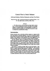
x Bus Fault: these errors can be caused by voltage or current glitches on the microprocessor I/O pins or on the system buses. They result in incorrect data transfer and, therefore, data corruption during processing (see Figure 1).
This work focuses on transient errors in systems based on the Motorola M68040© microprocessor. This processor is used in many critical systems like Automatic Traffic Control (ATC) of railways systems. Instead of using high costs military components or Triple Module Redundancy techniques, a dedicated watchdog processor is used to perform on-line system-level error detection. It interacts with the processor through the system bus, only. In order to detect and correct errors, the watchdog monitors the bus transfers and forces the processor to repeat unsuccessful transmissions. This technique allows high reliability also in case of long perturbations.
Despite the different locations and causes of faults, the error effects can be classified in two categories:
The paper is organized as follow: Section 2 describes the target fault model. Section 3 details the mechanisms used into the watchdog to tolerate different types of faults, whereas Section 4 gives an overview of the watchdog implementation. At last, Section 5 concludes the paper and presents the ongoing activities.
x Data Errors: they appear when the content of a variable stored in memory or inside a microprocessor register is altered. x Control Flow Errors: they appear when the content of a memory cell or a microprocessor register storing an instruction is altered, and the effect is the execution of an incorrect sequence of instructions. The Watchdog processor has been therefore designed with the goal of tolerating faults responsible of these two classes of errors.
2. The Fault Model In our work we deal with two main transient faults sources: radiations and electromagnetic interferences. The main effects of these sources are Single Event Upset (SEU) and voltage or current glitches. The SEU is one of the major sources of bit-flips in digital electronics. A bit-flip is an undesired change in the state of a memory cell. A SEU can cause the state of a memory cell to change from 0 to 1 or 1 to 0. Voltage and current glitches are noise induced on the circuit’s interconnections that can lead to a misinterpretation of a logic level. In a microprocessor based systems these errors can be located in three main areas: x Memory Fault: is one of the most common effects of noise in microprocessor systems. It usually consists of a SEU appearing in a memory location. Both program and data are stored in memory and can be affected by these errors. x Processor Fault: it is similar to the memory fault. The internal state of the processor is altered causing an erroneous execution of the program, with secondary effects like memory data corruption and incorrect operation of peripheral circuitries. It is caused by a SEU in an internal register of the processor.
Proceedings of the 9th IEEE International On-Line Testing Symposium (IOLTS’03) 0-7695-1968-7/03 $17.00 © 2003 IEEE
Figure 1: An Incorrect Data Transfer
3. The Watchdog Processor The main goal of the watchdog is to check the correctness of the data exchanged between the microprocessor and the external memory and to implement a control flow checking mechanism in order to guarantee the correct execution of a program. The watchdog is fully transparent to the processor, it is connected to the system bus, and monitors every transfer directed towards and from the M68040©. When it detects faults, it raises an interrupt in order to stop the execution of the program and to inform the processor that something is wrong. The two main strategies that have been implemented to address data and control flow errors
will be analyzed in the following sections. Section 3.3 describes the strategy used to detect bus faults.
Begin
Block1 [a]
3.1. Data protection Data stored in memory can be affected by transient faults during the execution of a program. To detect and correct data values, the watchdog has an internal memory where it stores a copy of the variables used by the program. In particular: x Each write operation of a variable performed by the processor to the memory is intercepted on the bus by the watchdog, which reads the value of the variable and creates a copy of it (shadow variable) inside its internal memory.
V3 V5 Block2 [b] Block3 [c] Block4 [d]
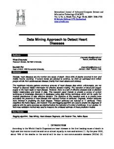
Control Node Branch Free Block
End
Figure 2: Control Flow Graph
x Each read operation performed by the processor is intercepted by the watchdog that checks between the value on the bus and the shadow value stored in its internal memory.
To check the control flow of a program the watchdog has solve two problems:
In this way every fault appearing in a variable stored in the system memory is detected. Obviously it is not possible to duplicate all the application variables inside the watchdog; only a subset of them can be duplicated through the watchdog mechanism. This subset is composed by the most critical variables (MCV) of the program. A variable is defined critical if, when affected by a fault, it can cause the program to terminate correctly but producing wrong results. The methodology to select the best subset of critical variables is explained in [10]. The addresses of the MCVs can be programmed in the watchdog before starting the execution of the target application.
x Check the branch free blocks are executed in a correct order.
The size of the memory used to store the MCVs allows trading-off between area overhead and reliability.
3.2. Control flow checking A bit flip in the application binary code stored in memory or occurring during an instruction fetch may cause a wrong execution of the program. Controlflow checking has become a widely studied approach to concurrently detect these classes of errors. The test aims at detecting erroneous sequences of instructions in a program execution [11] [12]. The main idea is to split the application program into elementary blocks with single entry. A generic program is represented by a so-called Flow Control Graph (FCG) (Figure 2) in which each Branch Free Block represents a sequence of consecutive instructions without branches whereas each Control Node represents a branch instruction.
Proceedings of the 9th IEEE International On-Line Testing Symposium (IOLTS’03) 0-7695-1968-7/03 $17.00 © 2003 IEEE
x Verify that the instructions inside a branch free block are correctly executed;
The first problem is addressed by calculating a signature for each branch free block. It is computed signing the opcode of the instructions of the branch free block. A golden signature is calculated off line and stored in the watchdog internal memory. At run time the watchdog computes again the signature of each block and compares it with the golden one. The second problem has been addressed in [13]. The authors proposed a signature scheme based on the regular expression formalism. The set of the allowed sequences of branch free blocks is represented using a complex regular expression. Each branch free block is coded using a label. The sequences of labels obtained by the execution of the branch free blocks are valid if they are recognized by the regular expression. The watchdog, by inspecting the sequence of instruction addresses on the address bus, is able to build the sequence of executed branch free block (i.e. the sequence of labels representing the blocks) and to check its correctness. It stores in its internal memory a table mapping each label with the address of the first instruction of the related branch free block. If one of the two signature mechanisms detects an error, the watchdog sends to the M68040© a bus error acknowledgment and updates its status register on an idle state, waiting for a reset.
3.3. Bus protection Data Protection and Control Flow Checking are
able to detect faults occurring on the system bus but they require modifying the target application. This is sometime not possible. To allow flexibility, the watchdog is able to implement a general bus protection strategy based on Automatic Repeat Request (ARR). Transient error occurring on the bus, are supposed to be extinguished until a limited number of bus cycles. When the ARR is activated, the watchdog starts to monitor the bus transfers between the M68040© and the system memory and ask the processor to repeat each transmission multiple times. The Watchdog stops to request new transfers when at least two consecutive transmissions return the same data. The watchdog receives all the information necessary to implements the ARR from the external bus and from the M68040© and not need any modification of the application. The ARR introduces a very high time overhead. Nevertheless it can be activate only when the target application cannot be modified or the level of reliability need to be very high. Furthermore the flexibility of the watchdog allows activating the ARR only for very critical portion of the program allowing to lower the final time overhead.
4. Watchdog implementation The watchdog has been described in VHDL. It receives all the information necessary to operate from the external bus and from the M68040©. The M68040©’s pins directly connected to the watchdog are TS (Transfer Start), TA (Transfer Acknowledge), and TEA (Transfer Error Acknowledge).
watchdog updates the MCV of the internal shadow memory. In both the two cases, if the watchdog detects an error at the very moment the M68040© reads or writes a datum, it sends to the processor an error signal, recognized as a bus error; x Check of signature (control of instruction flow): In the last case, if the data (correctly read) is a signature, it is subjected to a second check. The signature just read must be one of the possible ones, taking into account the whole structure of the program previously stored into the shadow memory. Only if the read signature is not one of the possible ones that can be received, the watchdog sends an error acknowledgment to the M68040© and stops working, otherwise it continues regularly. To evaluate the fault tolerance of the system, a testing program has been written. The testing program is endowed with a setup phase in which the MCVs are set and the signatures are properly chosen. The execution length of the testing program is of 30,22us, but this value is increased by the presence of the watchdog up to 50,22us due to the RETRY cycles. Faults are injected on the bus and the system memory by means of simulation. All the simulations differ each other for the duration of the single fault (fault’s length), ranging from 10ns to 200ns.
Every executable program that wants to make use of the watchdog has to transfer to its internal memory all the addresses of the chosen set of MCVs, the signatures and the structure of the program control flow. After that, the watchdog is initialized and the execution of the target application can begin to be monitored.
The fault injector is able to understand different execution of the testing program. A Wrong Execution is caused by undetected errors that can either modify the expected results or stop the execution of the program. Detection means that an error that has just occurred cannot be corrected by the watchdog. Correct Execution includes both those executions not affected by the injection of faults and also those executions in which errors have been corrected.
The watchdog is able to monitor the following operations:
Figure 3 shows the whole trend of the testing program’s results w.r.t. the injection’s length.
x Read and Write of generic data (no MCV or signature): the watchdog realizes that the data the M68040© is reading or writing is not a MCV or a signature and so it works in order to ensure the correctness of the data transfer, without involving the data stored in its internal memory; x Read and Write of MCV: when the watchdog realizes the data to be read is a MCV, after activating the bus-switch, it forces on the external bus the datum stored into its shadow memory. Whenever a MCV is to be written, the
Proceedings of the 9th IEEE International On-Line Testing Symposium (IOLTS’03) 0-7695-1968-7/03 $17.00 © 2003 IEEE
Figure 3: Fault injection results
5. Conclusions This paper presented a watchdog processor for the M68040© microprocessor. The main goal of the proposed architecture is to detect errors caused by radiations and electromagnetic interferences. The watchdog interacts with the processor through the system bus, in order to check the integrity of the most critical variables and the correct control flow of the executed application. We are currently finalizing the design in order to have an optimal synthesizable description of the circuit. The following step will be the implementation of fault injection experiments to demonstrate the capabilities of the implemented mechanisms.
6. References [1] B. W. Jonson, “Design and Analysys of Fault Tolerant Digital Systems”, Addison Wesley Publishing Company 1989. [2] D. K. Pradhan, “Fault-Tolerant Computer System Design”, Prentice Hall, 1996. [3] L.S Blanchard and D. Whitehead, “A study to assess the possible effects on radio based services of electromagnetic emission from the proposed increase of electrically powered public ad private transport”, Deliverable 5: Final Report, UK Transport Research Laboratory, October 2000. [4] M. Z. Ziaullah Khan and J. G. Tront, “Detection of upset induced execution errors in microprocessors”, IEEE International Test Conference, 1991, pp. 82–86 [5] D. P. Siewiorek, R. S. Swarz, Bedford, “The Theory and Practice of Reliable System Design”, MA:
Proceedings of the 9th IEEE International On-Line Testing Symposium (IOLTS’03) 0-7695-1968-7/03 $17.00 © 2003 IEEE
Digital, 1982, ch. 3. [6] R. E. Staehler, “Organization and objectives”, Bell Syst. Tech. J., vol. 56, pp. 119-124, Feb. 1977. [7] A. L. Hopkins, T. B. Smith, J. H. Lala, “FTMP – A highlyreliable fault-tolerant multiprocessor for aircraft ”, Proc. IEEE, vol 66, pp. 1221-1239, Oct 1978. [8] A. Mahmood, E. J. McCluskey, “Concurrent error detection using watchdog processors-a survey”, IEEE Transactions on Computers, Volume: 37 Issue: 2 , Feb 1988 Page(s): 160-174 [9] D. J. Lu, “Watchdog processor and VLSI”, National Electronic Conferenc, Volume: 34, Chicago, Oct 2728, 1980, Page(s): 240-245 [10] A. Benso, S. Chiusano, P. Prinetto, L. Tagliaferri, A C/C++ Compiler for Dependable Applications, The International Conference on Dependable Systems and Networks (FTCS-30), New York (NY), USA, June 2000, pp. 71-78 [11] S. S. Yau, F. Ch. Chen, “An Approach to Concurrent Control Flow Checking”, IEEE Transaction on Software Engineering, Vol. SE-6, No. 2, pp. 126-137, 1980. [12] R. Leveugle, T. Michel, G.Saucier, “Design of Microprocessors with Built-In On-Line test”, 20th International Symposium on Fault-Tolerant Computing (FTCS-20), pp. 450-456, 1990. [13] A. Benso, S. Di Carlo, G. Di Natale, P. Prinetto, L. Tagliaferri, Control-Flow Checking Via Regular Expressions, IEEE Asian Test Symposium (ATS 2001), Kyoto (J), November 2001, pp. 299-303