wavelet and the optimal number of level of resolution is carried out using the minimum description length (MDL) criteria. The proposed approach is tested for ...
Journal of Basrah Researches ((Sciences)) Volume 37. Number 4 A / 15 August ((2011)) 1-14
A Wavelet Packet Transform-Based Technique for the Discrimination of Inrush Currents from Faults in Three-Phase Transformer ISSN 1817 2695
Adel A. Obed, Majed A. Alwan and Waad N. Taboor Department of Electrical Engineering, College of Engineering, University of Basrah ((Received 6/4/2011, Accepted 22/6/2011))
Abstract: The inrush current occurs primarily when a transformer is energized. The magnitude of inrush current may be as high as ten times of transformer rated current which causes malfunction of differential protection system. Therefore, it is necessary to discriminate inrush current from faults. In this paper, a new approach of discrimination between inrush current and internal fault currents is proposed based on wavelet packet transform (WPT). The selection of optimal mother wavelet and the optimal number of level of resolution is carried out using the minimum description length (MDL) criteria. The proposed approach is tested for signal tripping using data collected from a simulink model of power three phase transformer for different cases that included inrush, internal fault currents and external fault currents. The simulated results clearly show that the proposed approach facilitates the accurate discrimination between inrush and fault currents in differential transformer protection. Keywords: Wavelet Packet Transform, Transformer Protection, Inrush and Faults Current
1- Introduction The power transformer is an important element in power system and it plays a basic role in both generation and distribution sites of a power system. The main protection for transformer is the differential protection because of its simple operation and sensitivity. One of the main reasons for wrong operation of differential protection for the transformer is the magnetizing inrush current. A possibility for false tripping may be caused by the magnetizing inrush current during energization. Inrush current occurs due to the flux saturation in the core. It contains harmonics due to nonlinearities of core saturation of currents, over excitation, residual magnetization and switching instant. The key problem of differential protection for the transformer is how to discriminate inrush current from internal fault currents [1-3]. Several techniques have been proposed in the literature. The conventional
approaches use the second harmonic component to restrain operation of the differential relay and to avoid tripping during inrush current [4,5]. However the methods based on second harmonic component are not sufficiently effective for differential protection relay because this component may be generated during some internal faults of the transformer windings due to current transformer (CT) saturation. In addition, the new low-loss amorphous core materials in modern power transformers is capable of producing inrush currents with low 2 nd and 5 th harmonic contents [6,7]. Beside the second harmonic approach, the previous works on differential protection of transformers include also artificial neural network (ANN)[8,9], fuzzy logic[10-12] and different features using S-transform [13,14]. These methods assumed some parameters of transformer artificially and the theories demand further researching. The magnetizing inrush current and the internal faults are non-stationary signals. Thus signal processing techniques can be employed for the discrimination between inrush and internal
Obed, Alwan & Taboor: A Wavelet Packet Transform-Based Technique for the Discrimination of Inrush …
faults in power transformer. The wavelet (WL) is more effective than short time Fourier transform (STFT) because the later does not track the signal dynamic property due to the limitations of the fixed window width. The wavelet packet transform (WPT) decomposes a signal from high frequency to low frequency bands according to time scale through an iteration procedure. The wavelet analysis has been used in differential protection [1,15] where current diagnosis is based on comparing the first level approximation with a predefined threshold value. The WPT is also employed to extract certain feature of the differential current to distinguish between the magnetizing inrush and different internal
2-Wavelet Packet Transform The advantage of analyzing a signal with wavelet is that enables one to study the local features of the signal with details matched to their characteristics scale. Moreover, the WPT enables making multiresolution analysis of a signal because it is possible to have both smooth wavelet with compact support and symmetry of the associated scaling functions which avoids bias for the locations of maxima and minima of the signal. Each level of resolution j in WPT consists of 2 j boxes generated by a tree of low pass and high pass filtering operations. The frequency bandwidth of a box decreases with increasing box number, i.e. with increasing box number, the frequency of resolution becomes higher while the time resolution is reduced [2]. The wavelet packet basis functions are localized at the time offering better signal approximation and decomposition. These basic functions are generated from one base function, the mother wavelet (t ) , or the scaling function (t ) if exists at scale S , dilation a and translation b as follows [2,7,16]. wS ,a ,b ( n ) 2 j / 2 W a ( 2 j ( n b )) (1)
fault currents [2]. The features are used as signatures which represent the values and the time locations of the coefficients of the second level details (dd 2 ) . In this paper, a new approach based on WPT is used for the discrimination of inrush currents from faults. Signatures which represent the values and the time locations of the coefficients depend on the second level details (ad 2 ) and (dd 2 ) are considered to discriminate between inrush currents and different fault currents. The method has been applied by considering different behaviors of the differential currents of internal faults, external faults as well as magnetizing inrush current.
f [n] is represented as a sum or orthogonal wavelet basis functions wS ,a ,b ( n ) as follows
f [n]
wS ,a ,b [n]Wa [n ] S
a
(2)
b
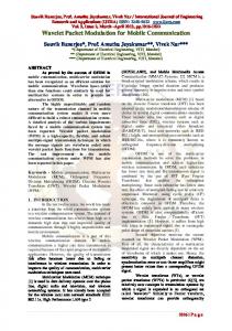
The implementation procedure of the WPT is shown in the decomposition tree of Fig.1. The vectors G and H stand for the low pass (LP) and high pass (HP) filters respectively. At the first level of decomposition, the original signal f [n ] with length N is divided into two sub-bands, a 1 ( n / 2) and d 1 (n / 2) , of the frequency bandwidth and sent to both HPF and LPF. Then the output of each half is farther cut in half of the frequency bandwidth to generate four sub-bands 2 2 2 aa (n / 4), ad (n / 4), da (n / 4), dd2 (n / 4) , then sent to a new level. This procedure is repeated until the original signal is being sampled to a certain level of F H Z which represents the highest frequency that the signal could contain.
where W a (n ) is the wavelet function coefficient matrix. In WPT, a discrete signal
2
Journal of Basrah Researches ((Sciences)) Volume 37. Number 4 A / 15 August ((2011)) 1-14
N 1
a 1 [ n]
f [n]
g (k ) f (n k )
(3)
h( k ) f ( n k )
(4)
k 0 N 1
d 1 [n ]
G
H
k 0
and the second level four sub-bands [2,7]: 1
G
G
H
aa
2
N /2 1
d1
a
ad
2
da
aa 2 [n]
dd
ad 2 [ n]
2
dd 2 [n ] The first level two sub-bands can be expressed as follows [2,7]: 3.Minimum Description Length (MDL) Criterion The minimum description length (MDL) criterion is an approach to select the best wavelet filter (mother wavelet function) and the best number of decomposition level to be retained for signal reconstruction [17]. This criterion is free from any parameter setting or thresholding which can be particularly useful for real data where the noise level is difficult to estimate [16]. The algorithm for this criterion is basically picking a function known as MDL ( k , n ) index defined for a discrete signal f [n ] as follows [2,7,17]: (k , j )
min{
3 k log N 2
N log 2
(k) 2 xj
W xj f [n] denotes to the vector of decomposition coefficients of f [n ] up to xj
(k )
(k )
Wxj f [n] denotes to the vector that contains k non-zero level j ,
xj
g (k ) d 1 ( n k )
(7)
h(k ) d 1 (n k )
(8)
k 0
MDL criteria index represents the penalty function that is increasing linearly with the number of the retained wavelet coefficients k , while the second term describes the logarithmic energy residual between x, j (k )
and . It should be noted that the x, j residual energy decreases as k increases. The number of coefficients k for which the MDL function reaches the minimum value, is considered as an optimal one. The wavelet filter can be optimized using the MDL criteria as well. It should be noted that a wavelet filter which is optimal for a signal, is not necessarily the best for another type of signals [2].
xj
(9) where 0 k N which represents the length of the signal f [n ] , 1 j M the total number of wavelet filter (level of resolution) used for the decomposition of the signal
f [n ] ,
(6)
k 0 N /2 1
Fig.1 Implementation procedure of WPT
X
h( k ) a 1 ( n k ) k 0 N /2 1
da 2 [ n]
MDL
(5)
k 0 N /2 1
H 2
g (k ) a1 (n k )
elements and (k ) is the hard threshold operation that keeps the k largest elements of xj in absolute value intact and set all other elements to zero. The first term of the
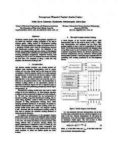
4. System Studied The system under consideration is the simulation model which is developed using Matlab/Simulink as shown in Fig. 2. The system comprises a 1MVA generator and 1kVA with 220/110 V three-phase transformer with both sides star connected and grounded naturals. The load taken is 1kW and the CT’s are represented by a gain for each side of primary and secondary. There are a large number of different type of internal faults and external faults before and after energization with and without load and different shapes for the magnetizing inrush current with and without load. The data collected in this simulation is
Obed, Alwan & Taboor: A Wavelet Packet Transform-Based Technique for the Discrimination of Inrush …
chosen for the differential current between the primary and the secondary current for a selected cases as follows 1- Magnetizing inrush current, unloaded 2- Internal fault current:
-
Primary double line to ground (DLG) fault loaded after energization 3- External fault current; - Secondary single line to ground (SLG) fault loaded after energization
Scope -K-K-
-KCT rati o
CT ratio
-K-
-K-Kdata
a
B
B
b
C
C
c
geneator
Breaker
+
A
a
+
i -
B
b
+
i -
C
c
+
i -
+
i -
To workspace
Three-Phase Transformer A
current measurement
i -
C
A
+
B
A
i -
load
Fig.2 Matlab/Simulink differential protection model
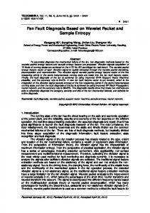
5.1.Optimal Selection of Mother Wavelet Filter and Level of Decomposition The optimal wavelet filter , mother wavelet function, can be selected by calculating the MDL index using equation (9). The procedure of MDL index is realized in flowchart shown in Fig.3. The MDL index is calculated after determining the wavelet coefficients by the decomposition procedure. There are several known wavelet families that can be used for power system application [7]. In this paper, the mother wavelets used are: *Orthogonal Wavelet Families 1-Daubechies(db4) 2-Daubechies(db10) 3-Coiflet(coif1)
5-Simulation Results In data collected waveforms, the differential current is taken for a simulation time of 0.2 sec. The sampling rate is 3.2 kH Z and it contains 64 samples to be processed using Matlab Wavelet toolbox . It is mentioned here that the primary line-to-line voltage is taken as is rated value of 220V for the cases of external and internal faults rather than reducing it in an actual cases to avoid any damage in the testing equipments.
4
Journal of Basrah Researches ((Sciences)) Volume 37. Number 4 A / 15 August ((2011)) 1-14
4-Symlet(sym2) *Biorthogonal Wavelet Families -B-Spline (bior1.1) The MDL is applied with three types of collected data. which are unloaded magnetizing inrush current, primary double line-to- ground fault loaded, and external single-line to ground fault loaded as mentioned in the previous section. The MDL index is calculated up to the second level of decomposition for each mother wavelet. The results of the MDL index for the inrush current are shown in Table I. The results of the MDL index for the primary side double phase to ground are shown in Table II and the results of the MDL index for the external single line- to-ground are shown in Table III TABLE I TWO-LEVEL MDL INDEX FOR INRUSH CURRENT DATA Mother Wavelet MDL(1) MDL(2) db4 1.5399 0.9865 coif1 5.68 4.7957 sym2 20.8061 1.8741 bior1.1 112.7782 11.1746 db10 10.1095 7.5879 TABLE II TWO-LEVEL MDL INDEX FOR DLG INTERNAL FAULT CURRENT DATA Mother Wavelet MDL(1) MDL(2) db4 3.3744 1.0476 coif1 70.7034 7.8594 sym2 62.5534 0.1653 bior1.1 174.3035 38.151 db10 4.592 3.3369 TABLE III TWO-LEVEL MDL INDEX FOR EXTRNAL SLG FAULT CURRENT DATA Mother Wavelet MDL(1) MDL(2) db4 3.1112 0.6934 coif1 6.0301 4.4436 sym2 15.4894 0.2691 bior1.1 184.4074 2.0319 db10 6.345 3.465
From the previous tables, it can be noted that (db4) has the smallest value of MDL index in the first level. Therefore it can be considered the optimal mother wavelet function. These low values of MDL(1) are due to the jumps of the data at the switching instant and some missing data.
Thus, MDL(1) may not provide accurate indication and the higher levels of resolution will include more detailed representation of the signal. The optimal level of decomposition j is reached when MDL( j ) is less than levels of higher j . Table IV presents four levels of MDL index using db4 mother wavelet. The second level has the lowest values of MDL index. Therefore, the second level is selected as the optimal level of decomposition TABLE IV FOUR-LEVEL MDL INDEX (db4) MDL(1) MDL(2) MDL(3) MDL(4) Current data Unloaded inrush Primary DLG fault External SLG fault
1.5399
0.9865
2.3746
1.8191
3.3744
1.0476
1.7611
1.8733
3.1112
0.6934
2.5005
1.7593
Re ad I a , I b , I c
I a2
f [n ]
I b2
Ic 2
Re ad level N
Calculate xj
xj
(k )
and
Wxj f [n],
xj (k ) xj
u sin g db4 (k )
Wxj f [ n]
Calulate & Write MDL index N 3 MDLx ( k , j ) min{ k log N log xj 2 2
No
MDL(( j ) MDL( j 1)
(k ) 2 xj
yes
stop
Fig (3) Flow chart of MDL index algorithm.
Obed, Alwan & Taboor: A Wavelet Packet Transform-Based Technique for the Discrimination of Inrush …
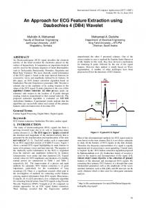
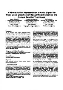
Figures (4) to (7) show the details coefficients in both first level ( d 1 ) and second level ( dd 2 ) and approximation coefficient on the second level ( ad 2 ). These figures show the time location of the WPT coefficients for different current data using the optimal wavelet mother ( db4 ) filter and optimal level of decomposition (level 2). It clearly shows the existence of the ( dd 2 ) coefficients in the cases of internal fault (secondary loaded SLG fault), and its absence in both cases of unloaded magnetizing inrush current and external loaded SLG fault. Figure (4) shows the WPT
coefficients d 1 , ad 2 , dd 2 and the time location for the unloaded magnetizing inrush current. Figure (5) shows the WPT coefficients d 1 , ad 2 , dd 2 and the time location for the external loaded SLG fault, while Fig (6) shows the WPT coefficients d 1 , ad 2 , dd 2 and the time location for the primary loaded internal DLG fault.
1
Scales 1/2
Detail ( d )
0
300
600 2
Scales 1/4
Approximation ( ad )
0
150
300 2
Scales 1/4
Detail ( dd )
0
150
300
Time (or space) 1
2
Fig.4 WPT first level details ( d ), second level details ( dd ) and 2 second level approximation ( ad ) coefficients of the unloaded magnetizing inrush current
6
Journal of Basrah Researches ((Sciences)) Volume 37. Number 4 A / 15 August ((2011)) 1-14
1
Scales 1/2
Detail ( d )
0
300
600 )
Scales 1/4
Approximation ( ad
2
0
150
300 2
)
Scales 1/4
Detail ( dd
0
150
300 Time (or space) 1
2
Fig.5 WPT first level details ( d and second level details ( dd ) and 2 second level approximation ( ad ) coefficient of the secondary loaded external single line to ground fault current
Obed, Alwan & Taboor: A Wavelet Packet Transform-Based Technique for the Discrimination of Inrush …
1
Scales 1/2
Details ( d )
0
300
600 2
Scales 1/4
Approximation ( ad )
0
150
300 2
Scales 1/4
Details ( dd )
0
150 Time (or space) 1
300 2
Fig.6 WPT first level details ( d ), second level details ( dd ) and 2
second level approximation ( ad ) coefficient of the primary loaded internal double line to ground fault current
8
Journal of Basrah Researches ((Sciences)) Volume 37. Number 4 A / 15 August ((2011)) 1-14
5.2 Testing of the Proposed Approach for Tripping Signal Two methods are used to discriminate between the inrush current and different fault currents, the first one is the proposed wavelet packet transform (WPT) and the other is the discrete Fourier transform (DFT). 5.2.1 Proposed wavelet packet transform method The (WPT) algorithm for power transformer protection is proposed by evaluating the coefficient of the (WPT) details ( dd 2 ) and the approximation ( ad 2 ) and comparing their values to a threshold values obtained from the power of these sub-bands which are helpful for all cases studied. The evaluation of the (WPT) coefficient can be down by filtering the signal with filters created by the optimal mother wavelet ( db4 ). This procedure is realized in Flowchart Fig.(7). Re ad I a , I b , I c
f [ n]
Ia
2
Ib
2
Ic
2
Calculate first level of decomposti on d 1 , a1 u sin g db 4
Calculate sec ond level of decompostion dd 2 , ad 2 u sin g db4
No
If dd 2 threshold 1 and ad 2
yes
threshold 2 tripping signal int ernal fault
Fig.7 Flow chart of the proposed (WPT)
5.2.2 Discrete Fourier transform (DFT): The harmonic restraint approach for differential protection is tested with the same collected data for comparison
purposes. A DFT with a window length of 16 samples is used to extract the 1st, the 2nd, and the 5th harmonics from the collected samples of the differential current. The sine and cosine components of the Fourier coefficients are computed using the following equations[16]
SK CK
2 N 2 N
N 1
2 kn ) N n 0 N 1 2 kn ) X ( n ) cos ( N n 0 X ( n ) sin (
(10) (11)
where N is the window length (16) samples, f [n] is the vector of collected differential current samples, n is the sample number, and k ( k 1,2,... N ) is the harmonic order. The magnitude of the kth harmonic ( FK ) can be determined as [6,16]
FK
Sk
2
Ck
2
(12)
The magnitudes are computed at each sampling step when the vector f [n] is updated. It was found that if the ratio F2 / F1 is higher than 95.5%, no tripping signal will appear (inrush current or external fault). Otherwise, a tripping signal will appear and will stop the algorithm. The ratio F5 / F1 has another effect on tripping signal. If this ratio is higher than 84.5%, no tripping signal will appear. For the case of magnetizing inrush current, the transformer is unloaded at the supply phase voltage of 220 V. Fig. (8) shows the three phase differential currents I a , I b , I c and the tripping signals representing the DFT and the WPT responses. It is to be noted that both trip signals remain low indicating a no-fault condition. The single line-to-ground external fault (phase A) occurred on the secondary side with a balanced Y connected load of the P=1000w. Fig.(9) shows the three phase differential currents I a , I b , I c and the tripping signals representing the DFT and
Obed, Alwan & Taboor: A Wavelet Packet Transform-Based Technique for the Discrimination of Inrush …
the WPT responses. It is to be noted that both trip signals remain low indicating a nofault condition. In the case of double line to ground internal fault between phases B and C, the transformer is loaded, and the fault takes place on the primary side of the transformer at t=1sec. after the transformer has been energized. Fig. (10) shows the three phase
Ic[A]
Ib[A]
Ia[A]
WPT
DFT
differential currents I a , I b , I c and two trip signals representing the WPT trip signal changed its status from low to high indicating that an internal fault has been detected in less than quarter a cycle, while the DFT trip signal changed its status in more than three quarters of a cycle.
Time[sec] Fig.8.Three-phase currents for the case of the unloaded magnetizing inrush current and both DFT and WPT response signals
10
WPT
DFT
Journal of Basrah Researches ((Sciences)) Volume 37. Number 4 A / 15 August ((2011)) 1-14
Time[sec]
Fig .9.Three-phase currents for the case of the external loaded single phase to ground fault current and both DFT and WPT response signals
WPT
DFT
Obed, Alwan & Taboor: A Wavelet Packet Transform-Based Technique for the Discrimination of Inrush …
Time[sec]
Fig.10 Three-phase currents for the case of the primary loaded double phase to ground internal fault current and both DFT and WPT response signals
12
Journal of Basrah Researches ((Sciences)) Volume 37. Number 4 A / 15 August ((2011)) 1-14
6. Conclusions This paper proposes a new approach to discriminate inrush current from faults based on WPT for using in differential protection of three-phase transformer. The selection of the optimal mother wavelet and the optimal number of decomposition is carried out using MDL criterion. The proposed approach evaluates the WPT coefficients of the second level ad 2 and dd 2 in which the values of these coefficients and their time location represent the features to discriminate the type of the investigated currents. Different simulated differential References 1- O. A. S. Youssef, “ A Wavelet-Based Technique for Discrimination Between Faults and magnetizing Inrush Currents in Transformers”, IEEE Trans. Power Delivery, Vol. 18, No. 1, PP. 170-176, Jan., 2003. 2- S. A. Saleh and M. A. Rahman, “Modeling and Protection of a ThreePhase Power Transformer Using Wavelet Packet Transform”, IEEE Trans. Power Delivery, Vol. 20, No. 2, PP. 1273-1282, April, 2005. 3- Q. Zhang and S. J. Sha Wang, “Identification Inrush Current and Internal Faults of Transformer based on Hyperbolic S-Transform”, Conference on Industrial Electronics and Applications, PP. 258-263, May, 2009. 4- R. L. Sharp and W. E. Glassburn, “ A Transformer Differential Relay with Second Harmonic Restraint,” Trans. AIEE, vol. 77, pp. 884–892, 1958. 5- B. A. Sykes and I. F. Morrison, “A Proposed Method of Harmonic Restraint Differential Protection of Transformers by Digital Computer,” IEEE Trans. Power App. Syst. vol. PAS-91, pp. 1266-1272, May 1972. 6- M. R. Zaman, “Artificial Neural Network Based Protection of Power Transformer,” Ph.D. dissertation, Memorial Univ. Newfoundland, St. John’s, NL, Canada, 1996.
currents data which are used to test the mentioned method and the simulation results show that the proposed approach facilitates the accurate discrimination between inrush and fault currents. The DFT harmonic restraint is used for comparison purposes. The proposed approach reveals fast, accurate and reliable method which can be used in differential protection of power transformers.
7- S. A. Saleh, “A Wavelet Packet Transform-Based Differential Protection of Three-Phase Power Transformers,” Master’s Thesis, Memorial Univ.f Newfoundland, St. John’s, NF, Canada, 2003. 8- L. D. Periz, A. J. Flechsig, J. L. Mendor, and Z Obradovic, “ Training of Artifical Neural Network to Discriminate between Magnetizing Inrush and Internal Faults”, IEEE Trans. Power Delivery, Vol. 9, No. 1, PP.434-441, 1994. 9- A. L. Oville-Fernandez, N. K. J. Ghonaim, and J. A. Valencia, “A FIRANN as a Differential Relay for Three Phase Power Transformer Protection”, IEEE Trans. Power Delivery, Vol.16, No. 2, PP. 215-218, 2001. 10- A.Wiszniewski and B. Kasztenny, “A multi criteria differential transformer relay based on fuzzy logic, IEEE Trans.Power Delivery, 10 (4), 17861792, 1995. 11- M.C.Shin, C.W.Park and J.H.Kim, “Fuzzy Logic -Based Relaying for Large Power Transformer Protection”, IEEE Trans.Power Delivery, 18 (3), 718-724, 2003. 12- H. Khorashadi, “Fuzzy-Neuro Approach to Investigating Transformer Inrush Current,” Transmission and Distribution Conference and Exhibition, pp. 1302-1306, May, 2006.
Obed, Alwan & Taboor: A Wavelet Packet Transform-Based Technique for the Discrimination of Inrush …
13- S. Jiao, S. Wang and G. Zheng, “A New Approach to Identify Current Based on Generalized S-Transform,” International Conference on Electrical Machines and Systems, pp. 4317-4322, Oct. 2008. 14- S. Jiao and H. Huang, “Research on Identification Between Inrush Current and Internal Faults of Power Transformer Based on H-S Transform,” 3rd International congress on Image and signal processing, pp. 3619-3624,2010. 15- M. G. Morante and D. W. Nicoletti, “A Wavelet-Based Differential Transformer Protection,” IEEE Trans. Power
Delivery., vol. 14, No. 4, pp. 1351– 1358, Nov. 1999. 16- E. Y. Hamid and Z. I. Kawasaki, “Wavelet-Based Data Compression for Power Disturbances Using Minimum Description Length Data,” IEEE Trans. Power Delivery, Vol. 17, No. 2, PP. 460–466, Apr. 2002. 17- N. Saito, “Simultaneous Noise Suppression and Signal Compression using a Library of Orthogonal Basis and the Minimum Description Length Criterion” in Wavelet in Geophysics. E. Foufoula-Georgiou and Kumar, Eds. New York: Academic, PP. 299-324, 1994
–
:
.
.
.
.
.
.
.
14