AbstractâWe present an FPGA accelerator for the Non- uniform Fast Fourier ..... and Xilinx EDK. (version 10.1) is used to run synthesis and place and route.
2010 18th IEEE Annual International Symposium on Field-Programmable Custom Computing Machines
Accelerating the Nonuniform Fast Fourier Transform using FPGAs Srinidhi Kestur, Sungho Park, Kevin M. Irick and Vijaykrishnan Narayanan Microsystems Design Laboratory (MDL), Department of Computer Science and Engineering, The Pennsylvania State University, University Park, PA - 16802 {kesturvy, szp142, irick, vijay}@cse.psu.edu FPGAs have been used mostly for custom-precision fixedpoint applications, GPUs have mostly been used for applications requiring floating-point computations. However, the computational and memory resources on FPGAs have tremendously increased, which has led engineers to adopt FPGAs for floating-point applications as well [6] [7]. In this paper, we describe an FPGA implementation for the NuFFT interpolation. We perform a sorting of the arbitrary samples using a Geometric Tiling based technique, which is implemented using a novel dynamic linked-list based memory mapping scheme. The actual convolution computation is performed by a Data Translator pipeline which utilizes novel multi-port memory structure and dynamic coordinate generation with multiple parallel kernel pipelines. The kernel itself is designed to be a plug-andplay module which uses a look-up-table based framework to support various kernel functions. We compare our implementation with a relevant CPU and GPU version and show that the FPGA provides an energy efficient acceleration for various kernel functions and convolution window sizes, which is scalable with the data-size. The rest of the paper is organized as follows. Section II provides the background and problem specification, Section III describes the algorithm for FPGA implementation, Section IV describes the hardware implementation in detail, Section V gives the experimental setup and Section VI discusses the results. Finally, Section VII discusses the related work and the conclusion is provided in Section VIII.
Abstract—We present an FPGA accelerator for the Nonuniform Fast Fourier Transform, which is a technique to reconstruct images from arbitrarily sampled data. We accelerate the compute-intensive interpolation step of the NuFFT Gridding algorithm by implementing it on an FPGA. In order to ensure efficient memory performance, we present a novel FPGA implementation for Geometric Tiling based sorting of the arbitrary samples. The convolution is then performed by a novel Data Translation architecture which is composed of a multi-port local memory, dynamic coordinate-generator and a plug-and-play kernel pipeline. Our implementation is in single-precision floating point and has been ported onto the BEE3 platform. Experimental results show that our FPGA implementation can generate fairly high performance without sacrificing flexibility for various data-sizes and kernel functions. We demonstrate up to 8X speedup and up to 27 times higher performance-per-watt over a comparable CPU implementation and up to 20% higher performance-per-watt when compared to a relevant GPU implementation.
I. I NTRODUCTION The Fast Fourier Transform (FFT) has been applied in almost every area of modern science including fields as diverse as astronomy, digital signal processing, computational biology and medicine. While FFT provides an efficient way to compute the Discrete Fourier Transform (DFT) with O(N logN ) complexity, it can only be applied when the captured data is on a regularly sampled grid such as a cartesian grid. In applications such as synthetic aperture radar(SAR), medical imaging, geosciences and seismic analysis, the data acquisition is carried out using irregular/nonequispaced sampling. The class of problems which deal with reconstruction from non-equispaced data is called the Nonuniform Fast Fourier Transform(NuFFT) [1] also referred to as Non-equispaced Fast Fourier Transform(NFFT) [2] [3] and Generalized Fast Fourier Transform(GFFT) [4]. A popular technique for NuFFT is the Gridding method [5] [2] which provides high computation efficiency with reasonable reconstructed image quality. The basic idea of gridding is to re-sample the raw measurement data on the cartesian grid by performing an interpolation. Then, the inverse FFT is used to reconstruct the target image. The interpolation step is known to be most time-consuming - in some cases up to 90% of overall NuFFT execution time [3] - and in this paper we focus on accelerating this step. Since the interpolation is to be performed on arbitrarily sampled data, cache-based computing platforms such as CPUs suffer due to lack of inherent data locality. Traditional computing paradigms have provided scientists and engineers with the desired performance for various applications. However, over the past few years, the performance gains from CPUs have slowed down and FPGAs and GPUs have emerged as the platforms of choice for accelerating computationally demanding applications. While 978-0-7695-4056-6/10 $26.00 © 2010 IEEE DOI 10.1109/FCCM.2010.13
II. BACKGROUND AND P ROBLEM S PECIFICATION A. Nonuniform Fast Fourier Transform (NuFFT) Let M denote the number of non-equispaced samples x in a given sampling set. Let fj denote the complex Fourier coefficient corresponding to the sample positioned at xj . Let IN denote the set of equispaced cartesian grid cells of dimension d and N denote the number of cells in this set. For a finite number of complex Fourier coefficients fc k corresponding to grid cells k, the Non-uniform Discrete Fourier Transform (NuDFT) [2] can be given as ∑ −2πikxj fj = fc (1) k · exp kϵIN
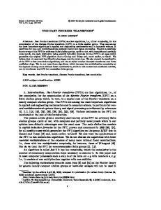
This computation requires O(M N ) arithmetic operations. The main idea of NuFFT is to use standard FFTs in combination with an approximation scheme that is based on a window function. This function needs to be mutually well localized in time and frequency domain. Several such window functions have been proposed [4] [8]. The Gridding algorithm for NuFFT is shown in fig 1. It consists of the following steps - (i) To compensate for non-uniform 19
sampling, the samples are scaled with a weighting function in density-compensation step. (ii) This is followed by a convolution of the non-uniform samples on to a regular cartesian grid using a suitable kernel function. (iii) The inverse FFT is computed to transform the grid to time domain. (iv) Finally a convolution roll-off correction is done where the input grid is divided by the fourier transformed convolution kernel. An oversampling factor (σ > 1) is used to reduce aliasing artifacts which allows the use of smaller interpolation kernels. The NuFFT computes the approximate NuDFT with O(M + N logN ) complexity [2].
Figure 1.
III. T HE FPGA A PPROACH The main challenge to extract peak performance for the NuFFT interpolation is to ensure efficient memory bandwidth utilization, for which data locality is necessary. Since the target array is a uniform 2D array, we use the rowmajor order to store it in FPGA Main memory(DRAM). Multiple target samples in contiguous memory locations can be accessed by doing a memory read/write in burst mode. This inherent data locality in the target array is absent for the source array which is an array of arbitrarily ordered samples. Hence, it is necessary to intelligently reorder the source array before convolution computation. We use a simple Geometric Tiling as a pre-processing stage, to sort the source points based on their spatial locality. This is followed by the actual Convolution with the specified kernel function in the Data Translator. A. Data Representation Both the source and target are complex data arrays where the coefficients and the coordinates of each source sample are represented in single precision floating point. The input source samples are stored in the memory (DRAM) in the following format - (x, y, re, im) where x and y are the x and y coordinates of the source sample and re and im are its real and imaginary coefficients. Hence, each source point is 128bits wide. However, the target array is a regular 2D array and we choose to generate its coordinates on-the-fly. Hence each target point is stored in memory as - (re, im), which is 64bits wide. The arithmetic operations are implemented using the pipelined Xilinx floating point operators [11] generated using Xilinx Core Generator.
The Gridding algorithm for NuFFT
B. BEE3 FPGA Platform We map our FPGA implementation on to the BEE3 [9] platform, which is a distributed computing platform having four Virtex5 LX155T FPGAs [10], with each FPGA having 24320 logic slices, 212 Block RAMs and 128 DSP48E units. Each FPGA has access to 16 GB of DDR2-400 SDRAM organized in two DRAM channels with two DIMM slots per channel giving a total memory footprint of 64 GB per BEE3 platform [9].
B. Geometric Tiling Geometric Tiling is an indexing technique used for indexing and partitioning a matrix computation [12], and many variations of Geometric Tiling have been applied to the interpolation problem for optimizing performance on a CPU [13]. However, for the FPGA, the goals of Geometric Tiling are - (i) To enable multiple independent sub-blocks for convolution computation and (ii) To perform the indexing and sorting in just 1 pass through the data-set. So, we choose a simple tiling scheme where the cartesian grid is logically partitioned into equal-sized rectangular tiles as shown in Fig 2. Each tile is assigned a unique tile-index in row-major order. All source samples located within a particular tile are assigned its tile-index and are stored in the DRAM in a pseudo-contiguous memory space. Within a tile, the source samples can be in any order. Similarly, the target array is also logically divided into tiles but no reordering is necessary since it is already stored in a contiguous memory space. Every source tile has an associated target tile (both share the same region on the grid and hence the same tileindex) and convolution is carried out on every source, target tile pair. A tile is hence considered as the macro unit of computation and the entire convolution operation can be seen as a loop over all the tiles. This reordering procedure creates data locality for memory accesses within a source tile which enables efficient bandwidth utilization even for source array. In order to make the computation of each tile independent of other tiles, the target tile needs to have all the target
C. Problem Specification We refer to the arbitrarily sampled input data array as the source array (S) and the resulting uniformly sampled array on the cartesian grid as the target array (T ). The window for convolution can be given by the distance metric c or by an integer convolution window (W ). Each source sample needs to be convolved with a W × W window of target samples around it. We refer to the NuFFT interpolation step as Data Translation, which can be represented by the following equation M −1 ∑ G(i, j) · S(j) if ∥ti − sj ∥2 1 cycles). The MPLM is used in the DT pipeline as the target buffer. The target tile is fetched from DRAM and stored in the target buffer in row-major format. Since, each PE requires a read and write from/to the target buffer, DT can support up to 2B PEs, by careful address generation to avoid conflicts. The data-width of each port is equal to the bit-width of a target sample (64 bits) and the depth of each bank is a HDL parameter. We have set the number of banks, B = 4 which enables up to 8 parallel PEs.
Figure 7.
Local Source Reorder Stage Input parameters: N x × N y: Size of the target array W : Convolution window size 1. Synthesis-time parameters: (dx, dy): unit sample distance in X and Y dimensions dx = (Xmax − Xmin)/(N x − 1) dy = (Y max − Y min)/(N y − 1) 2. Run-time hardware computation while(source buffer is not empty) Read a source sample from the source buffer; 1 Xstep = f loor(x − Xmin) × ( dx ); 1 Y step = f loor(y − Y min) × ( dy ); ′ if ((Xstep − Xstep < W )and(Y step − Y step′ < W )) Write the source sample back into the FIFO; else Dynamic Coordinate Generation;
Figure 8.
Pseudo-code for Local Source Reorder Stage
N x × N y × 8 bytes. The goal of this stage is to generate the coordinates of the target samples in the W × W window of the source sample. An additional requirement is to generate N umP E coordinates per cycle since each PE operates on a unique target sample. Since W and N umP E are both HDL parameters, this task is not very straight-forward.The algorithm to generate N umP E indices and hence the coordinates is shown in Fig 9. The first step is to generate the array indices (Xindex, Y index) of each target sample in the W × W window around (Xstep, Y step). The target index generation is handled by the parameterized and completely pipelined index generator. This module is implemented in fixedpoint precision since the array indices are integers. It uses the parameters W and N umP E, accepts an array index (Xstep, Y step) as input and generates N umP E indices every cycle for ceil(W ×W/N umP E) cycles. Then the coordinate generator generates the coordinates by multiplying the array indices by dx and dy and adding the coordinates of the frame origin (Xmin, Y min) as shown in Fig 9.
Multi-port Local Memory with 4 banks
3) The Local Source Reorder stage: The pseudo-code for Source Reorder stage is as shown in Fig 8. The computation of a source tile begins with reading a source sample from the source buffer. The x and y coordinates of the source sample are used to determine the array indices (Xstep, Y step) of the nearest target sample, where Xstep and Y step are the column-index and row-index respectively. If two source samples are spatially very close to each other, then several of the target samples in the W × W window of the sources will be reused among the source samples. In such a case, since the same target sample will be read and written multiple times, it is essential to prevent read-after-write(RAW) data hazards, which might occur due to the deep data translation pipeline. We handle this by doing a selective reordering of the source samples as and when required, by implementing a reorder buffer. The reorder buffer consists of a fifo along with some control logic and hence is a conditional circular buffer. We check to determine if there are target samples common between successive source samples. This can happen if the Xstep and Y step of successive source samples are within the window W . If they are, we then feed the source sample back into the fifo, so as to defer the computation to a later stage. 4) Dynamic Coordinate Generator: The coordinates of the source and target samples are the operands for the kernel function. While the coordinates of the source samples are stored in memory, we generate the target coordinates dynamically. This approach results in memory savings of
Dynamic Coordinate Generator: 1. Index Generation W for(i = −(ceil( W 2 − 1)); i