carrier frequencies of the two femtosecond lasers has been achieved. It is also ... 100 MHz. The phase shift between the two 100 MHz signals can be used to control ... Figure 1. Experimental setup for timing synchronization of two fs lasers. ... 0 Hz B. 1.0. 0.8. 0.6. 0.4. 0.2. 0.0. 40. 30. 20. 10. 0. 8 GHz PLL. 100 MHz PLL.
journal of modern optics, 2002, vol. 49, no. 3/4, 401 ±409
Active synchronization and carrier phase locking of two separate mode-locked femtosecond lasers ROBERT K. SHELTON, LONG-SHENG MA, HENRY C. KAPTEYN, MARGARET M. MURNANE, JOHN L. HALL and JUN YE JILA, National Institute of Standards and Technology and University of Colorado, and Department of Physics, University of Colorado, Boulder, CO 80309-0440, USA (Received Received 15 March 2001, revision received 5 May 2001) Abstract. Two independent mode-locked femtosecond lasers are synchronized to an unprecedented precision. The rms timing jitter between the lasers is 4.3 fs observed within a 160 Hz bandwidth over tens of seconds, or 26 fs within a 50 kHz bandwidth. Novel multi-stage phase-locked loops help to preserve this ultrahigh timing resolution while setting on arbitrary delay between the two pulse trains (0±5 ns). Under such synchronization, phase locking between the carrier frequencies of the two femtosecond lasers has been achieved. It is also demonstrated that the same level of synchronization can be achieved with two lasers at di erent repetition frequencies.
The ability to synchronize a passively mode-locked laser to an external reference, or to a second laser, has many applications in science and technology. Previous work in synchronizing two mode-locked Ti:sapphire lasers has demonstrated timing jitter of at best a few hundred femtoseconds (fs) [1, 2]. Since it is now routine to generate pulses with duration 4 .3 fs tim ing jitte r (1 6 0 H z b a nd wi d th)
10 0 0
1
2
3
4
5
Tim e (se c o nd ) 2
(d) Timing Jitter (fs/sqrt(Hz))
10
Timing Jitter (fs)
1000
4 2
1 4 2
0.1 -6
10
-5
10
-4
10
-3
10
-2
10
Averaging Time (s)
-1
10
0
10
(e)
Small gain
100 10
Intermediate gain
1
High gain 0.1 Phase detector noise floor 0.01
3
4 5 6 7 89
1
2
3
4 5 6 7 89
10
2
3
4 5
Fourier Frequency (kHz)
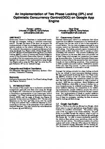
Figure 5. Timing jitter noise analysis. (a) A 10 ms direct digitization record of the sum frequency generation. Also shown is the time-expanded trace. The pulse-to-pulse intensity ¯uctuation is below 0.4%, similar to the original laser intensity ¯uctuation. (b) Sum frequency generation observed with a 50 kHz bandwidth. The left trace shows two pulses optimally overlapped and the right trace shows two pulses o set by a half width. (c) Sum signal observed under a 160 Hz bandwidth, showing an rms timing jitter noise of 4.3 fs. (d) Allan variation of the timing stability, showing the maximum jitter occurs around 10±100 ms. (e) Fourier frequency spectrum of the error signal from the 8 GHz phase-locked loop.
the intensity ¯uctuations can be translated linearly into timing jitter noise using the calibrated slope of the correlation peak. For a maximum intensity of the sum frequency light at 50 units, and the FWHM of the cross-correlation peak at 164 fs, we can conservatively estimate the conversion scale of the slope at 3.3 fs/unit. The rms timing noise from the right trace is thus determined to be ¹26 fs at a 50 kHz bandwidth. At higher bandwidths, the jitter does not increase. If we use a bandwidth of 160 Hz (equivalent to 1 ms averaging time) the resultant intensity ¯uctuations of the summing light shown in ®gure 5 (c) indicates rms timing jitter noise of 4.3 fs. We have recorded such stable performance over periods extending to nearly a minute. The advantage of the high harmonic PLL over the 100 MHz loop is particularly clear from the recorded sum frequency intensity, which exhibits ¯uctuations more than 20 times bigger when under the 100 MHz control.
Synchronization and locking of two mode-locked fs lasers
407
The synchronization lock can be maintained for durations of several hours, limited by the dynamic range of the servo PZT and by thermal expansion. A simple integrator stage can be implemented to control the temperature of the laser baseplate to extend the lock time even further. It is interesting to explore further the issue of the timing jitter noise vs its characteristic time scales (or equivalently its frequency spectrum). Allan variance analysis [12] is a powerful technique developed for the study of frequency noise of stable oscillators in the time domain. The approach compares adjacent measurements segmented within certain time windows. In this ®rst-di erence calculation one is able to separate and isolate processes based on their time scales. This is useful to identify time scales at which ¯uctuations are the largest. From the time record of the timing jitter noise shown in ®gure 4 (b) and (c), we calculate the Allan variance of the timing jitter. The result is shown in ®gure 5 (d). The data points ‰&Š correspond to the fast time record [the right trace in ®gure 5 (b)] while the data points (*) correspond to the longer record [shown in ®gure 5 (c)]. It is clear from this analysis that the dominant timing jitter noise occurs within 10±100 ms, a region where the gain of the PLL loop is rolling o from the low frequency end while the external perturbations to the laser are increasing from the high frequency end. However, it is satisfying to ®nd that the timing jitter noise never exceeds 20 fs at any time scale. These results can be con®rmed through the equivalent analysis of the error signal within the PLL servo loop [13]. Figure 5 (e) shows the Fourier spectrum analysis of the error signal at di erent gain settings. When the loop is operated stably with a high gain, within a frequency p range from DC to 5 kHz the error signal is very close to the limit (µ 0:1 fs= Hz) set by the intrinsic noise ¯oor of the 8 GHz mixer, i.e. the phase comparator used in the PLL. (We have removed the last two data points below 250 Hz that were a ected by the DC o sets of the Fouriertransform spectrum analyser.) A small servo p bump appears near 10 kHz and rolls o to a ¯at noise ¯oor near 0:14 fs= Hz. Integrating the noise density over the interested spectral range (from DC to 50 kHz) would yield an rms timing jitter noise of ¹30 fs, slightly larger than that indicated by the direct time domain data. When the two lasers are well synchronized, heterodyne beat between the two corresponding sets of combs can be recovered with impressive S=N. Figure 1 shows the beat detection at another beam port independent from the synchronization work. A grating (1200 line/mm) is used to limit the optical bandwidth for the heterodyne beat. The beat detection e ectively measures the di erence in the carrier-envelope o set frequency between the two fs combs. Therefore by stabilizing the beat frequency to a mean value of 0 Hz, the carrier-envelope phase evolution dynamics of one laser will be closely followed by the second laser. Locking of this beat frequency to 0 Hz can be conveniently implemented using an acousto-optic modulator (AOM). One laser beam passes through the AOM, picking up the AOM’s frequency o set. The beat is then phase locked to the AOM’s drive frequency, e ectively removing the AOM frequency from the beat. Figure 6 (a) illustrates the di erence between the phase-locked and unlocked cases. When unlocked, the carrier beat frequency has a standard deviation of a few MHz with 1 s averaging time. Figure 6 (b) shows the recorded beat frequency signal under phase locked condition. With an averaging time of 1 s, the standard deviation of the beat signal is 1.3 Hz.
408
R. K. Shelton et al.
(d1 - d2)
(a) Phase lock activated
Frequency Hz (d 1 - d 2)
10
(b)
5 MHz
Sdev = 1.3 Hz with 1-s counter gate time
5
0
-5 -10 0
500
1000
1500 2000 2500 3000 3500 Time (second) Figure 6. (a) Di erence in the carrier frequency beat between phase-locked and unlocked cases. When unlocked, the standard deviation of the beat frequency is a few MHz at 1 s averaging time. (b) Record of the carrier beat signal between the two fs lasers when they are synchronized and phase locked. The beat frequency under the locked condition shows a standard deviation of 1.3 Hz at 1 s averaging time.
The ¯exibility of this synchronization system is demonstrated by locking two independent lasers working at di erent repetition frequencies. The 81st harmonic of the repetition rate of laser 1, still operating at 100 MHz, is compared to the 90th harmonic of laser 2, now running at 90 MHz. The two pulse trains will then collide in the time domain every 100 ns, leading to a sum-frequency pulse train at a 10 MHz repetition-rate. The result is shown in ®gure 7, where the top trace re¯ects the summing frequency generation and the bottom trace is the second harmonic generation of the 100 MHz laser. Notice the slight decrease in the second harmonic intensity when sum frequency generation occurs with two pulses overlapped. This approach can be generalized to produce sum- and di erencefrequency generations with arbitrary repetition rates, yet perfectly synchronized to the master frequency. In summary, we have synchronized two independent mode-locked femtosecond lasers to an unprecedented precision. The remaining rms timing jitter between the lasers is 4.3 fs observed within a 160 Hz bandwidth over tens of seconds, or 26 fs within a 50 kHz bandwidth. This ultrahigh timing resolution is available through the entire dynamic range of pulse repetition period (10 ns). Such a degree of synchronization is the basis for realization of an optical carrier phaselocked loop between independent femtosecond lasers [14]. We have also demonstrated that such synchronization can be achieved with two lasers at di erent repetition frequencies. The techniques developed should prove to be invaluable in many research areas of ultrafast science and extreme nonlinear optics.
409
SHG
(from 100 MHz laser)
SUM
Synchronization and locking of two mode-locked fs lasers
0
100
200
300
ns
Figure 7. Sum frequency generation from two synchronized fs lasers that have di erent repetition rates, one at 90 MHz and the other at 100 MHz. The second harmonic signal from the 100 MHz laser is also shown. Notice the slight decrease in the second harmonic signal when sum frequency generation occurs with two pulses overlapped.
Acknowledgments We are indebted to D. Anderson and KMLabs for the loan of pump lasers. We also thank S. T. Cundi for stimulating discussions. The work at JILA is supported by the National Institute of Standards and Technology, NASA, National Science Foundation and the Research Corporation.
References [1] Spence, D. E., Dudley, J. M., Lamb, K., Sleat, W. E., and Sibbett, W., 1994, Opt. Lett., 19, 481. [2] Crooker, S. A., Betz, F. D., Levy, J., and Awschalom, D. D., 1996, Rev. Sci. Instru., 67, 2068. [3] Schoenlein, R. W., Leemans, W. P., Chin, A. H., Volfbeyn, P., Glover, T. E., Balling, P., Zolotorev, M., Kim, K.-J., Chattopadhyay, S., and Shank, C. V., 1996, Science, 274, 236. [4] Kobayashi, K., Miura, T., Ito, S., Zhang, Z. G., Torizuka, K., and Endo, A., 2000, Nucl. Instrum. Methods A, 455, 239. [5] Teets, R. , Eckstein, J., and HAÈnsch, T. W., 1977, Phys. Rev. Lett., 38, 760. [6] Baklanov, Y. V., and Chebotayev, V. P., 1977, Appl. Phys., 12, 97. [7] Udem, Th., Reichert, J., Holzwarth, R., and HAÈnsch, T. W., 1999, Phys. Rev. Lett., 82, 3568; Udem, Th., Reichert, J., Holzwarth, R., and HAÈnsch, T. W., 1999, Opt. Lett., 24, 881. [8] Diddams, S. A., Jones, D. J., Ye, J., Cundiff, S. T., Hall, J. L., Ranka, J. K., Windeler, R. S., Holzwarth, R., Udem, Th., and HAÈnsch, T. W., 2000, Phys. Rev. Lett., 84, 5102. [9] Ye, J., Hall, J. L., and Diddams, S. A., 2000, Opt. Lett., 25, 1675. [10] Jones, D. J., Diddams, S. A., Ranka, J. K., Stentz, A., Windeler, R. S., Hall, J. L., and Cundiff, S. T., 2000, Science, 288, 635. [11] Asaki, M. T., Huang, C.-P., Garvey, D., Zhou, J., Kapteyn, H. C., and Murnane, M. M., 1993, Opt. Lett., 18, 977. [12] Allan, D. W., 1966, Proc. IEEE, 54, 221. [13] Tsuchida, H., 1999, Opt. Lett., 24, 1641. [14] Shelton, R. K. , Ma, L.-S., Kapteyn, H. C., Murnane, M. M., Hall, J. L., and Ye. J. (to be published, 2001).