Rice University, Houston, Texas 77005 and. M. Q. Phan§. Dartmouth College, Hanover, New Hampshire 03755-8000. A novel technique is introduced to detect ...
JOURNAL OF GUIDANCE, CONTROL, AND DYNAMICS Vol. 28, No. 5, September–October 2005
Actuator Failure Detection Through Interaction Matrix Formulation B. H. Koh∗ Dongguk University, Seoul 100-715, Republic of Korea Z. Li,† P. Dharap,† and S. Nagarajaiah‡ Rice University, Houston, Texas 77005 and M. Q. Phan§ Dartmouth College, Hanover, New Hampshire 03755-8000 A novel technique is introduced to detect and isolate the failures of multiple actuators connected to a system. The failure of actuator considered in this study could be any type of erroneous input that is different from the commanded one. The interaction matrix technique allows the development of input-output equations that are only influenced by one target input. These input-output equations serve as an effective tool to monitor the integrity of each actuator regardless of the status of the other actuators. Although the procedure requires the knowledge of analytical model of the system being tested, the analytical redundancy can be experimentally predetermined through standard input-output-based system identification algorithms such as observer/Kalman-filter identification (OKID) and eigensystem realization algorithm (ERA). This method is capable of real-time actuator failure detection and isolation under any type of input excitation. Both numerical simulations of a spring-mass-damper system and a laboratory experiment using eight-bay NASA truss structure verify the feasibility of the proposed method.
I.
Introduction
tures such as aircraft wings, bridges, space structures, and buildings rapidly adopt the smart materials that inherently incorporate control theory into their host structure. A smart structure with a network of robust sensors and high-performance actuators can elaborately accomplish either vibration control or structural health monitoring.8 Accordingly, the performance of a smart structure relies on the integrity of embedded sensors and actuators. For instance, unexpected actuator failure, such as debonding of piezoelectric material from its host structure, can destabilize the closed-loop system to pose a significant threat to the safety of structure.9 It is thought that actuator failures occur when the inputs to the system are different from the command inputs at some unknown actuators for some unknown time instants. In many situations when a structure has multiple actuators and sensors in different locations, each output of the structure is simultaneously influenced by all different inputs. Hence, simply comparing the response of individual measurement point on the structure does not give us much information about which actuator or when it has failed. For successful identification of actuator failure, each input and output relationship should be decoupled in a systematic way, that is, influences from all other actuators on output measurements should be eliminated except the only actuator being examined. This paper provides a novel technique to identify actuator failure in dynamic systems. The concept of interaction matrix is introduced and employed to achieve this objective. Previous studies10−12 show that the condition of the existence of interaction matrix can eliminate state variables so that only input-output relationship represents the system’s dynamics. The application of interaction matrix spans from predictive control,10 state estimation,11 and disturbance separation in system identification.12 In the study of identifying the system of disturbance-free dynamics, the interaction matrix explicitly eliminates the dependence of the state variables so that unknown disturbance inputs can be separated from the system and its inputoutput model. The key idea of this study is to eliminate the influences of unexamined inputs from measured outputs so that the deviation or failure of specific actuator can be manifested as a nonzero residual signal. The imposed condition of the existence of interaction matrix allows for the elimination of the dependence of all other inputs except the one being examined. Specifically, the interaction matrix provides a mathematical framework in which a series of special input-output
T
O accommodate a fault-tolerant control system, successful detection and isolation of actuator/sensor failure should be guaranteed along with reliable system identification. There have been several studies to diagnose actuator failure in control systems, and many of them exploit model-based analytical redundancy strategies.1,2 The analytical redundancy approaches became more popular in many industrial applications because hardware redundancy, such as a replication of identical hardware components (actuator/sensor), is more expensive, restricted, and sometimes difficult to implement in practice. The key element of analytical redundancy is to diagnose faults in a system by analyzing the generated residuals between a priori analytical model and available system measurements. Theoretically, residual or error signals should be zero-valued for a healthy case, whereas deviated nonzero values are considered to be an indication of system failure.3 Hence, the first step for failure detection is to develop a mathematical algorithm that accentuates the residual signal when a fault has occurred in a system. So far, parity space (consistency checking4,5 ) and observer-based methods6,7 have been widely used for the residual generation. Once residual signals are detected, the next step is to separate the source of the failure, a so-called fault isolation. The significance of the studies related to actuator failure detection is attributed to the effort of developing an adaptive control system that can compensate for the consequence of actuator failure in flight, power, or process control systems. Recently, various types of strucReceived 1 July 2004; revision received 11 November 2004; accepted c 2004 by the American for publication 17 November 2004. Copyright � Institute of Aeronautics and Astronautics, Inc. All rights reserved. Copies of this paper may be made for personal or internal use, on condition that the copier pay the $10.00 per-copy fee to the Copyright Clearance Center, Inc., 222 Rosewood Drive, Danvers, MA 01923; include the code 0731-5090/05 $10.00 in correspondence with the CCC. ∗ Assistant Professor, Department of Mechanical Engineering, 3-26 Pildong, Chung-gu; formerly Research Associate, Department of Civil and Environmental Engineering, Rice University, Houston, TX 77005. Member AIAA. † Graduate Student, Department of Civil and Environmental Engineering. ‡ Associate Professor, Departments of Civil and Environmental Engineering and Mechanical Engineering and Material Science. § Associate Professor, Thayer School of Engineering. Member AIAA. 895
896
KOH ET AL.
equations (or error functions) can be formulated to detect and isolate each unknown actuator failure. Because the underlying theory is to decouple the influence of specific input error from the overall outputs of the system, the method does not require a bank of failure hypotheses from an a priori model. The proposed method successfully identifies actuator failures in both numerical simulation of a springmass-damper system and experimental tests on eight-bay NASA truss structure. Note that this method is directly applicable to online system monitoring and allows any type of input excitation.
II.
( p)
Ci ends with ABi , not Bi . Also, u i (k), and Ti are
x(k + p) = A p x(k) + Cu p (k),
y p (k) = O x(k) + T u p (k) (2)
where u p (k) and y p (k) are column vectors of input and output data going into p steps into the future starting with u(k) and y(k), respectively,
u p (k) =
u(k) u(k + 1) .. .
,
y p (k) =
u(k + p − 1)
y(k) y(k + 1) .. .
(3)
y(k + p − 1)
For a sufficiently large value of p to be determined later, C is an (extended) n × pr controllability matrix, O is an (extended) pq × n observability matrix, and T is a pq × pr “Toeplitz” matrix of the system Markov parameters, C = [A p − 1 B, . . . , AB, B],
0 CB
T = C AB .. . C Ap −2 B
O = [C, C A, . . . , C A p − 1 ]T
0 0
0 ···
··· ···
CB .. .
0 .. .
··· .. .
0
···
C AB
CB
0
0 0 .. .
(4)
( p)
+ B1 u 1 (k + p − 1) + · · · + Br u r (k + p − 1)
(5)
( p)
y p (k) = O x(k) + T1 u 1 (k) + · · · + Tr u r( p) (k)
�
Ci = A p − 1 Bi , . . . , A2 Bi , ABi
0 0
··· ···
C Bi .. .
0 .. .
···
C ABi
0 0 .. .
0 C Bi
Comparing the definitions in Eq. (6) to those in Eq. (4), notice that they are defined for each input i. Furthermore C ends with ABi (not Bi ), and Ti leaves out the last zero column. The reason for this will become clear later. An interaction matrix Mi is introduced by adding and subtracting the product Mi y p (k) to Eq. (5) as follows: ( p)
x(k + p) = A p x(k) + C1 u 1 (k) + · · · + Cr u r( p) (k) + B1 u 1 (k + p − 1) + · · · + Br u r (k + p − 1) + Mi y p (k) − Mi y p (k)
( p)
= A p + Mi O x(k) + (C1 + Mi T1 )u 1 (k) + · · · + (Cr + Mi Tr )u r( p) (k) − Mi y p (k) + B1 u 1 (k + p − 1) + · · · + Br u r (k + p − 1)
(7)
Premultiplying the preceding equation by C yields
( p)
y(k + p) = C A p + C Mi O x(k) + (CC1 + C Mi T1 )u 1 (k) + · · · + (CCr + C Mi Tr )u r( p) (k) − C Mi y p (k) + C B1 u 1 (k + p − 1) + · · · + C Br u r (k + p − 1)
(8)
For each input i, we now impose conditions for the product C Mi in the preceding equation so that in Eq. (8) coefficients of state x(k) ( p) terms and the input vectors u j (k) vanish identically except for that input, C A p + C Mi O = 0 CC j + C Mi T j = 0,
∀ j �= i
(9)
For example, for the first input (i = 1), C M1 is required to satisfy
�
C M1 [O, T2 , . . . , Tr ] = − C A p , CC2 , . . . , CCr
�
(10)
Let us examine the conditions for the existence of the product C Mi (which implies the existence of Mi for independent outputs) by taking advantage of the fact that Eq. (9) is a set of linear equations. There are q( pq) = pq 2 unknown elements in C Mi vs a total of qn + (r − 1)q( p − 1) = qn + q(r − 1)( p − 1) equations. A necessary condition for the existence of C Mi is pq 2 ≥ qn + q(r − 1)( p − 1) p(q − r + 1) ≥ n − r + 1
x(k + p) = A p x(k) + C1 u 1 (k) + · · · + Cr u r( p) (k)
B = [B1 , B2 . . . , Br ],
(11)
Therefore p must be chosen such that
Because we are dealing with actuator failure detection, it is necessary to expand the preceding equation to show the contribution of each individual input i = 1, 2, . . . , r :
where
C A p − 2 Bi
(1)
An actuator failure is considered to occur when an actuator produces an input to the plant that is different from a commanded input. In the following, r special input-output equations will be developed, one for each actuator. Each equation will reveal if an actuator is experiencing a failure regardless of the status of any remaining actuators. This is possible if there exists for each actuator an input-output equation that involves the only actuator being examined, whereas the output measurements are influenced by inputs from all actuators. At first sight, it is not intuitively obvious if such relationship exists, what structure these equations possess, and how they are related to and can be designed from the preceding state-space model. The interaction matrix (M-matrix) formulation provides a mechanism to answer these questions in a straightforward manner. The derivation starts from the state-space model [Eq. (1)] as follows. By repeated substitution for some p ≥ 0,
0 C Bi
Ti = C ABi .. .
Consider an nth-order, r -input, q-output controllable and observable discrete-time model of a system in state-space form: y(k) = C x(k)
u i (k + p − 2)
Mathematical Formulations
x(k + 1) = Ax(k) + Bu(k),
( p)
u i (k) =
u i (k) u i (k + 1) .. .
�
(6)
(12)
The preceding condition causes the matrix and the product C Mi to have at least as many rows as columns. An examination of the structure of this matrix and its information content further reveals that it is generally full (column) rank for independent inputs in which case the existence of C Mi is ensured as long as Eq. (12) is satisfied. Satisfaction of Eq. (12) also requires that q − r + 1 > 0, which means that the number of independent sensors must be at least equal to the number of independent actuators (q ≥ r ) so that failures among actuators can be distinguished. A similar analysis can be performed by imposing the condition for Mi instead of C Mi , and this leads to the same conclusion. In other words, the imposed condition of interaction matrix Mi is independent from output matrix C.
897
KOH ET AL.
For each input i, we have ( p)
y(k + p) = (CCi + C Mi Ti )u i (k) − C Mi y p (k) + C B1 u 1 (k + p − 1) + · · · + C Br u r (k + p − 1)
(13)
To detect whether the ith actuator fails, we are interested in obtaining a relationship among the input and output measurements that does not involve any other actuators except the ith actuator. Up to this point, the interaction matrix Mi has eliminated all such dependence except for the remaining terms C B1 , C B2 , . . . , C Br for which it has no influence. The remaining terms (except C Bi ) can be eliminated by premultiplying Eq. (13) with a row vector that is orthogonal to all remaining column vectors C B j , j �= i, NiT (C B j ) = 0,
∀ j �= i
(14)
Because q ≥ r , such a vector Ni can be easily found (subject to normalization factor). Premultiplying Eq. (13) by Ni produces a scalar equation that involves all measured outputs and the ith input alone ( p)
Fig. 1
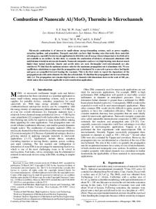
Three-input, three-output spring-mass-damper system.
by solving the set of linear equations given in Eq. (9), and Ni is determined from Eq. (14). In general the product C Mi that satisfies Eq. (9) is not unique. The pseudoinverse solution via the singular value decomposition produces a minimum-norm solution for C Mi while satisfying Eq. (9) exactly. Such a minimum-norm solution is expected to be advantageous because it results in small gains for Eq. (20) and thus does not amplify the effect of measurement noise. The singular value decomposition also provides the opportunity to eliminate sources of numerical ill-conditioning by truncating relatively small singular values if desired. Once C Mi and Ni are determined, Eqs. (21) and (22) give the formulas for the required coefficients of the ith actuator failure detection equation.
NiT y(k + p) = NiT (CCi + C Mi Ti )u i (k)
III.
− NiT C Mi y p (k) + NiT C Bi u i (k + p − 1)
(15)
To arrive at an actuator failure detection equation, we replace the actual input u i (k) to the plant by a sum of commanded (thus known) input u¯ i (k) and actuator error z i (k) in Eq. (15): NiT
y(k + p) =
NiT (CCi
+ C Mi Ti )
�
( p) u¯ i (k)
+
( p)
ei (k + p) = NiT (CCi + C Mi Ti )z i (k) + NiT C Bi z i (k + p − 1) (17) Equation (16) becomes ei (k + p) = NiT y(k + p) + NiT C Mi y p (k) ( p)
− NiT (CCi + C Mi Ti )u¯ i (k) − NiT C Bi u¯ i (k + p − 1)
(18)
Failure of the ith actuator can be detected by monitoring ei (k). When there is no actuator failure, z i (k) = 0, it follows that ei (k) = 0. Thus when ei (k) �= 0, it can be interpreted that ith actuator fails. Let us now examine the structure of the actuator failure detection equation (18) from the perspective of design and usage. Shifting time index back by p results in ei (k) = NiT y(k) + NiT C Mi y p (k − p) ( p)
− NiT (CCi + C Mi Ti )u¯ i (k − p) − NiT C Bi u¯ i (k − 1)
(19)
First, it is a scalar equation, one for each actuator. Second, it assumes the general form ei (k) = α0 y(k) + α1 y(k − 1) + · · · + α p y(k − p) + β1 u¯ i (k − 1) + β2 u¯ i (k − 2) + · · · + β p u¯ i (k − p)
(20)
For an r -input and q-output system (q ≥ r ), each coefficient α0 , α1 , . . . , α p is a 1 × q row vector, whereas each coefficient β1 , β2 , . . . , β p is a scalar. For the ith actuator, these coefficients are related to those of the original state-space model by
�
[β p , β p − 1 , . . . , β2 , β1 ] = − NiT (CCi + C Mi Ti ), NiT C Bi
03 × 3
I3 × 3
−M−1 K
−K −1 C
C = [I3 × 3
Finally, the actuator error terms are separated from the rest of the equation by defining
�
Ac =
�
− NiT C Mi y p (k) + NiT C Bi [u¯ i (k + p − 1) + z i (k + p − 1)] (16)
�
�
( p) z i (k)
[α p , α p − 1 , . . . , α1 , α0 ] = NiT C Mi , NiT
Simulation Results
Consider the following three-input, three-output, sixth-order dynamical system (Fig. 1):
(21)
�
(22)
Thus given a state-space model A, B, C, D, it is straightforward to form A p , O, Ci , Ti , Di from which the product C Mi is calculated
� ,
Bc =
03 × 3
M−1
03 × 3 ]
(23)
where m 1 = m 2 = m 3 = 1 kg, c1 = c2 = c3 = 0.05 N·s/m, and k1 = 20, k2 = 30, k3 = 50 N/m,
m1 M= 0 0
0 m2 0
0 0 , m3
k1 + k2 −k2 K= 0
c1 + c 2 −c2 C= 0 −k2 k2 + k3 −k3
−c2 c2 + c 3 −c3
0 −k3 k3
0 −c3 c3 (24)
The system is sampled with an interval �t = 0.1 s from which a discrete-time representation is derived (with the usual assumption of a zero-order-hold on the input) for the subsequent determination of the actuator failure detection equations. Because n = 6, q = 3, and r = 3, the condition p(q − r + 1) ≥ n − r + 1 is satisfied with p ≥ 4. Although any value of p ≥ 4 can be used, let us choose p = 4 in this numerical example. For each actuator i, the product C Mi is calculated by solving Eq. (9) and Ni from Eq. (14). The length of Ni is normalized to one. The coefficients for the actuator error equations given in Eq. (20) are computed from Eqs. (21) and (22). During a 50-s time interval, suppose the following failure profile occurs. Actuator number 1 fails during the time interval 10 ≤ t ≤ 15 s and 30 ≤ t ≤ 35 s, actuator number 2 fails during 10 ≤ t ≤ 15 s, and actuator number 3 fails during 15 ≤ t ≤ 35 s. An actuator is considered to fail when it produces an input to the plant that is different from a commanded input. The commanded inputs are taken to be random excitation in this case although any other input histories can be used. The actuator errors e1 , e2 , e3 describe correctly the preceding failure profile as shown in Fig. 2. Note that the failure profile for each actuator is determined correctly regardless of whether any other actuator fails or not.
IV.
Experimental Results
This section discusses the experimental validation of aforementioned actuator failure detection algorithm. Two key elements of the experiment are system identification and failure detection. The portion of system identification provides a baseline model, which represents a healthy state of the system and constitutes the coefficients of scalar function defined in Eq. (20). Failure detection
898
KOH ET AL.
a)
b)
c) Fig. 2
Error function profile for a spring-mass-damper system: a) actuator 1, b) actuator 2, and c) actuator 3.
Table 1
Three sensor sets: (A), (B), and (C) in Fig. 4b
Location set
Bay (sensor) number
(A) (B) (C)
Fig. 3
Picture of eight-bay NASA truss structure.
process begins by feeding the measured outputs into Eq. (20) and monitoring its residual signal in real time. If the residual signal exhibits nonzero value, the corresponding actuator is considered to be malfunctioning. A.
Test Setup
Two electromagnetic shakers serve as independent actuators that are attached to the test structure. The test bed is a 4.0-m-long, standard NASA truss structure with 109 struts and 32 node balls, which connect the struts in truss assembly.13 This cantilevered truss spans eight square bays as shown in Fig. 3. Each strut is made of hollow aluminum tube having 0.5-in. outer diameter with 0.1-in. thickness. The Young’s modulus of strut is E = 7.03e10 N/m, and each shaker connects with the structure through a flexible stinger rod to transmit the input force only in axial direction. The first shaker is located at the free end, and the second one is installed in the middle section of the truss. Figure 4 shows a schematic of the truss structure, illustrating the position of two shakers, boundary conditions,
Bay 4 (sensor 1), bay 8 (sensor 4) Bay 5 (sensor 2), bay 6 (sensor 3) Bay 5 (sensor 2), bay 8 (sensor 4)
and locations of sensors. Notice that two hangers vertically support the truss to prevent vertical motions as shown in Fig. 4a. Also, both shakers are placed on the same plane to ensure the excitation of only horizontal modes. In this experiment, accelerometers are used as output sensors. For a two-input system, the minimum number of independent sensors to identify each actuator failure is two (q ≥ r ). Hence, a pair of accelerometers is installed at three different sets of locations, (A), (B), and (C), as shown in Table 1. The location (A) is collinear with two actuators at bay 4 (sensor 1) and 8 (sensor 4), whereas (B) is located at bay 5 (sensor 2) and bay 6 (sensor 3) so that both accelerometers are not collinear with actuators as shown in Fig. 4b. The location (C) lies in bay 5 (sensor 2) and bay 8 (sensor 4) such that one accelerometer becomes collinear with actuator, whereas the other one does not. The experiment has been repeated to collect input-output data from each different sensor location. In the experiment, shakers are driven by band-limited white-noise inputs from the amplifier, which is connected to a dSPACE boardimplemented computer. The driving inputs to the structure are measured from force transducers installed between stinger and node-ball joint of truss structure. Because Eq. (1) does not hold a direct transmission term D, the derivation of error function has been slightly modified to accommodate acceleration output. The Toeplitz matrix in Eq. (4) can be modified as
D CB
T = C AB .. . C Ap −2 B
0 D
0 ···
··· ···
CB .. .
D .. .
··· .. .
0
···
C AB
CB
D
0 0 .. .
(25)
KOH ET AL.
899
a)
b) Fig. 4 Configuration of three-dimensional truss structure: a) schematic of truss, showing boundary conditions; and b) overhead view of truss, showing the location of shakers and accelerometers.
Similar to Eq. (8), we include the product of Mi y p (k) and premultiply the equation with C such that
p
y(k + p) = C A p + C Mi O x(k) + (CC1 + C Mi T1 )u 1 (k) + · · · + (CCr + C Mi Tr )u r( p) (k) − C Mi y p (k) + D1 u 1 (k + p) + · · · + Dr u r (k + p)
(26)
Here, the necessary condition for the existence of C Mi becomes p(q − r + 1) ≥ n, and the imposed condition eliminates the state terms and input vectors similar to Eq. (9) as follows: ( p)
y(k + p) = (CCi + C Mi Ti )u i (k) − C Mi y p (k) + D1 u 1 (k + p) + · · · + Dr u r (k + p)
(27)
If we premultiply Eq. (27) with a row vector Ni to get rid of D1 , D2 , . . . , Dr except Di , the actuator failure detection equation with acceleration output finally becomes ei (k) = NiT y(k) + NiT C Mi y p (k − p) ( p)
− NiT (CCi + C Mi Ti )u¯ i (k − p) − NiT Di u¯ i (k)
(28)
The major difference in developing an error function with acceleration measurement is the presence of D terms in diagonal components in the Toeplitz matrix [see Eq. (25)]. Also, C Bi terms are replaced with Di in most of the derivation. B.
Results
The test structure is simultaneously excited by random inputs from both shakers. Acceleration measurements are recorded with
sampling time, �t = 0.001 s up to 50 s. Based on collected inputoutput data, observer/Kalman-filter identification–eigensystem realization algorithm (OKID-ERA) has been employed for system identification.14−17 The order of the identified state-space model has been retained as 160 states. The number of retained states is chosen from numerous trials having different number of states, and the identified model with 160 states shows the most accurate estimation and prediction result among all others. From this identified state-space model, natural frequencies of the truss structure for the first two modes are identified as 13.1 and 61.3 Hz, which correspond to first two in-plane bending modes, respectably. The third global mode is not distinguishable from individual member’s local modes, which typically show up after 80 Hz (Ref. 13). The identified state-space model has been formulated to an input-output equation (i.e., actuator error function) for each individual actuator. Having obtained baseline input-output data, failures of actuators are simulated, experimentally, by turning off and on the shakers intermittently. Similar to the spring-mass-damper simulation, shaker 1 turns off for the interval 20 ≤ t ≤ 40 s, whereas shaker 2 sequentially turns off during the interval 10 ≤ t ≤ 15 s and 30 ≤ t ≤ 40 s. In other words, the actuator failure in this experiment is simulated by turning off the power of shakers for unknown time intervals. Figure 5 exhibits test result in which the profile of error function ei (k) correctly indicates the instant of failure of ith actuator. Each scalar function independently generates nonzero error signal corresponding to the correct failure instants, regardless of the condition of other actuator. In Fig. 5, two sensors are collinear with each actuator, implying that input forces are directly transmitting to the outputs through a strut member [sensor location (A)]. Figures 6 and 7 also present the test result of different sets of sensor locations (B) and (C), respectively.
900
KOH ET AL.
Fig. 5
Error function profile from measurements of sensors 1 and 4: location (A).
Fig. 6
Error function profile from measurements of sensors 2 and 3: location (B).
Comparison of Figs. 5–7 reveals that the location of the sensors is not a critical factor in terms of quality of error signal. Furthermore, it appears that a small number of sensors (only two accelerometers) sufficiently identifies actuator failure in a considerably complicated system. However, the directional properties of sensors are crucial because the unexcited mode of dynamics such as vertical motion cannot be measured. In this experiment, both shakers and sensors are aligned with the same horizontal direction. Therefore, two sensors are enough to distinguish the failure of actuators. It is intuitively obvious that only the observable dynamics of the system can be attributed to the formulation of input-output error function.
The proposed method does not require a mathematical model of the test structure in physical coordinates such as stiffness, mass, and damping matrices. The formulation of individual actuator error function only requires input-output data, measured from the healthy state of the system. However, as is obvious from both experiment and the formulation of input error function, the quality of identified state-space model is a critical factor to obtain distinguishable error signals over the general level of measurement noise. Because the measurement noise could be significant in practical application, the closed-loop type technique8 that enhances the sensitivity of error signal would be a reasonable approach to improve the signal-tonoise ratio.
KOH ET AL.
Fig. 7
V.
Error function profile from measurements of sensors 2 and 4: location (C).
Conclusions
This proof-of-concept study demonstrates the performance of newly developed actuator failure detection algorithm. Through the concept of interaction matrix in state-space framework, a series of decoupled input-output error functions have been formulated. Each error function provides an indicative measure for actuator failures by producing nonzero residual signal when the actuator fails to produce command inputs. In the NASA eight-bay truss experiment, the proposed algorithm successfully identifies failures of two electromagnetic shakers that are attached to the truss structure. Considering the limited number of measurements and the complexity of the structure, test results are in close agreement with simulated example, ensuring the capability of the proposed procedure in detecting and isolating the simultaneously and arbitrarily occurring multiple actuator failures.
Acknowledgments The authors acknowledge the support of the Texas Institute for the Intelligent Bio-Nano Materials and Structure for Aerospace Vehicles, funded by NASA Cooperative Agreement NCC-1-02038. At the time of the study, B. H. Koh was affiliated with Rice University.
References 1 Menke,
901
T. E., and Maybeck, P. S., “Sensor/Actuator Failure Detection in the Vista F-16 by Multiple Model Adaptive Estimation,” IEEE Transactions on Aerospace and Electronic Systems, Vol. 31, No. 4, 1995, pp. 1218–1229. 2 Frank, P. M., “Fault Diagnosis in Dynamic Systems Using Analytical and Knowledge-Based Redundancy—A Survey and Some New Results,” Automatica, Vol. 26, No. 3, 1990, pp. 459–474. 3 Chen, J., and Patton, R. J., Robust Model-Based Fault Diagnosis for Dynamic Systems, Kluwer International Series on Asian Studies in Computer and Information Science, Vol. 3, Kluwer Academic, 1999, pp. 35–44. 4 Chow, E. Y., and Willsky, A. S., “Analytical Redundancy and the Design of Robust Failure Detection Systems,” IEEE Transactions on Automatic Control, Vol. 29, No. 7, 1984, pp. 603–614. 5 Lou, X., Willsky, A. S., and Verghese, G. C., “Optimally Robust
Redunancy Relations for Failure Detection in Uncertain Systems,” Automatica, Vol. 22, No. 3, 1986, pp. 333–344. 6 Clark, R. N., Fosth, D. C., and Walton, V. M., “Detecting Instrument Malfunctions in Control Systems,” IEEE Transactions on Aerospace Electronic Systems, Vol. 11, No. 4, 1975, pp. 465–473. 7 Seibold, S., and Weinert, K., “A Time Domain Method for the Localization of Cracks in Rotors,” Journal of Sound and Vibration, Vol. 195, No. 11, 1996, pp. 57–73. 8 Koh, B. H., “Damage Identification of Smart Structures Through Sensitivity Enhancing Control,” Ph.D. Dissertation, Thayer School of Engineering, Dartmouth College, NH, March 2003. 9 Sun, D., and Tong, L., “Closed-Loop Based Detection of Debonding of Piezoelectric Actuator Patches in Controlled Beams,” International Journal of Solids and Structures, Vol. 40, No. 10, 2003, pp. 2449–2471. 10 Phan, M. Q., Lim, R. K., and Longman, R. W., “Unifying Input-Output and State-Space Perspectives of Predictive Control,” Dept. of Mechanical and Aerospace Engineering, Princeton Univ., TR 3044, Princeton, NJ, Sept. 1998. 11 Lim, R. K., Phan, M. Q., and Longman, R. W., “State Estimation with ARMarkov Models,” Dept. of Mechanical and Aerospace Engineering, Princeton Univ., TR 3046, Princeton, NJ, Oct. 1998. 12 Goodzeit, N. E., and Phan, M. Q., “System Identification in the Presence of Completely Unknown Periodic Disturbances,” Journal of Guidance, Control, and Dynamics, Vol. 23, No. 2, 2000, pp. 251–259. 13 Kashangaki, T. A.-L., “Ground Vibration Tests of a High Fidelity Truss for Verification of on-Orbit Damage Localization Techniques,” NASA TM 107626, May 1992. 14 Phan, M. Q., Horta, L. G., Juang, J.-N., and Longman, R. W., “Linear System Identification via an Asymptotically Stable Observer,” Journal of Optimization Theory and Applications, Vol. 79, No. 1, 1993, pp. 59–86. 15 Juang, J.-N., Phan, M. Q., Horta, L. G., and Longman, R. W., “Identification of Observer/Kalman Filter Markov Parameters: Theory and Experiments,” Journal of Guidance, Control, and Dynamics, Vol. 16, No. 2, 1993, pp. 320–329. 16 Phan, M. Q., Horta, L. G., Juang, J.-N., and Longman, R. W., “Improvement of Observer/Kalman Filter Identification (OKID) by Residual Whitening,” Journal of Vibration and Acoustics, Vol. 117, April 1995, pp. 232–238. 17 Juang, J.-N., and Pappa, R. S., “An Eigensystem Realization Algorithm for Model Parameter Identification and Model Reduction,” Journal of Guidance, Control, and Dynamics, Vol. 8, No. 5, 1985, pp. 620–627.