ADAM: Run-time Agent-based Distributed Application. Mapping for on-chip Communication. Mohammad Abdullah Al Faruque, Rudolf Krist, and Jörg Henkel.
42.2
ADAM: Run-time Agent-based Distributed Application Mapping for on-chip Communication Mohammad Abdullah Al Faruque, Rudolf Krist, and Jörg Henkel University of Karlsruhe, Chair for Embedded Systems, Karlsruhe, Germany {alfaruque, krist, henkel} @ informatik.uni-karlsruhe.de
ABSTRACT Design-time decisions can often only cover certain scenarios and fail in efficiency when hard-to-predict system scenarios occur. This drives the development of run-time adaptive systems. To the best of our knowledge, we are presenting the first scheme for a runtime application mapping in a distributed manner using agents targeting for adaptive NoC-based heterogeneous multi-processor systems. Our approach reduces the overall traffic produced to collect the current state of the system (monitoring-traffic), needed for runtime mapping, compared to a centralized mapping scheme. In our experiment, we obtain 10.7 times lower monitoring traffic compared to the centralized mapping scheme proposed in [8] for a 64×64 NoC. Our proposed scheme also requires less execution cycles compared to a non-clustered centralized approach. We achieve on an average 7.1 times lower computational effort for the mapping algorithm compared to the simple nearest-neighbor (NN) heuristics proposed in [6] in a 64 × 32 NoC. We demonstrate the advantage of our scheme by means of a robot application and a set of multimedia applications and compare it to the state-of-the-art run-time mapping schemes proposed in [6, 8, 19]. Categories and Subject Descriptors: C.3[Special-purpose and application-based systems]: Real-time and embedded systems General Terms: Algorithms, Design Keywords: Agent-based application mapping, On-chip communication
1. INTRODUCTION AND RELATED WORK2 Intel projects the availability of 100 billion transistors on a 300mm die by 2015 [4] which allows to integrate thousands of processors or equivalent logic gates on a single die. Heterogeneous Processing Elements (PEs), i.e. different types of instruction set processors or reconfigurable hardware on such an architecture, are proposed for building an energy-efficient system [19]. Besides the low power concern regarding computation, communication in such an architecture is another dominant factor since a scalable but light-weight communication infrastructure is needed on-chip [4]. This motivates toward the development of a tile-based heterogeneous Multiprocessor System on Chip (MPSoC) interconnected by a Network on Chip (NoC) [1, 7, 9, 13]. In general, all related work proposes to design an application-specific system where the parameters for the fabricated chip are adjusted at design time. The more complex a system grows the more it must be able to handle those situations efficiently that are unpredictable at design time. In this case the system needs to adapt itself to the new situation and therefore, the System on Chip (SoC) needs to be designed with the capability of self-adaptiveness in mind. Self-adaptation in SoC design is relatively new. The idea of adaptivity in future SoC design is introduced in [11, 14]. Taking the same spirit into NoC-based architecture design, we are the first to propose an adaptive on-chip communication scheme into [11]. An adaptive system needs to map the tasks of an application to various PEs at run-time without interfering the currently executing applications. To do this in a transparent way is a challenging research topic.
To solve the problem of mapping tasks to respective processing elements, several design-time (off-line) mapping algorithms have been proposed in related work. In [15], Branch and Bound-based, in [16] Genetic Algorithm-based, and in [12] heuristic-based mapping algorithms are proposed. But an adaptive system that changes its configuration over time requires a re-mapping/run-time mapping of applications. Possible reasons for the necessity of a run-time mapping are listed in Section 2. In [19] the authors extend the MinWeight algorithm proposed in [5] for solving the problem of runtime task assignment on heterogeneous processors. The task graphs are restricted to a small number of vertices or a large number of vertices with a degree of no more than two. Authors in [6] investigate the performance of several mapping heuristics promising for runtime use in NoC-based MPSoCs with dynamic workloads, targeting NoC congestion minimization. The work presented in [8] proposes an efficient technique for run-time application mapping onto a homogeneous NoC platform with multiple voltage levels. Their work is limited to a homogeneous architecture. A separate control network besides the data network is used which represents an extra overhead in terms of area and energy consumption. The state-ofthe-art run-time mapping work [6, 8, 19] has used a Centralized Manager (CM) for conducting the job of mapping which is not scalable in the context of hundreds or even thousands of cores that may soon be integrated on a SoC. It suffers from a single point of failure, larger volume of monitoring traffic1 , central point of communication around the CM (hot-spot), and scalability issues. The concept of task migration is an integral part of the run-time application mapping. The study of task migration to move a currently executing task between different processors which are connected by a network has already been a research focus in the distributed and parallel computing domain [20]. Now it is used to facilitate run-time application mapping in adaptive heterogeneous MPSoCs. Work presented in [2, 17] discuss the issues related to the task migration for MPSoC design, i.e. the cost to interrupt a given task, save its context, transmit all data to a new IP, and restart the task in the new IP. In our work we use this approach though the details of task migration are out of the scope of this paper. The rest of the paper is organized as follows: In Section 2, we present our motivation and novel contribution. In Section 3, we introduce our ADAM architecture whereas in Section 4, our novel clustering algorithm and agent-based run-time application mapping are explained in detail. Experimental results are discussed in Section 5 with Section 6 concluding the paper.
2. MOTIVATION AND NOVEL CONTRIBUTIONS Let us motivate the need of an agent-based distributed application mapping for NoCs by means of a simple scenario. We study a 32 × 32 NoC with a mesh topology. Some events that may require a re-mapping at run-time for an adaptive system where design-time mapping algorithms fail are given below: • On-line detection of hardware faults. • To minimize run-time system costs (i.e. to save energy because of the low battery status). • When the user requirements change, e.g. the user wants to switch video playback to a higher resolution.
Permission to make digital or hard copies of all or part of this work for personal or classroom use is granted without fee provided that copies are not made or distributed for profit or commercial advantage and that copies bear this notice and the full citation on the first page. To copy otherwise, to republish, to post on servers or to redistribute to lists, requires prior specific permission and/or a fee. DAC 2008, June 8–13, 2008, Anaheim, California, USA. Copyright 2008 ACM ACM 978-1-60558-115-6/08/0006 ...$5.00.
1 Monitoring-traffic is defined in this paper as the traffic which is caused by collecting information about the state of the tiles, ni ∈ N (see Def. 2)
760
• When an adaptive system tries to configure the underlying NoC infrastructure (i.e. changing the routing algorithm and the buffer assignment) and if it fails, then the mapping instance of the application needs to be changed [11].
state mapping request received
State-of-the-art run-time mapping is handled using a Centralized Manager (CM) which may bear the following problems: • • • •
Single point of failure. Higher computational cost to calculate mapping inside CM. Large volume of monitoring-traffic. Point of hot-spot as every tile sends the status of the PE to the CM after every instance of mapping. It increases the chance of bottleneck around the CM.
global agent negotiation
application mapping
suitable cluster found QoS reqr. not met
To solve the problem of a static design-time mapping algorithm which may require a high computational effort, we need a scheme that can perform a low-cost (execution time) mapping scheme inside a virtual cluster (see Def. 3) constructed at run-time. We solve the problems of a centralized mapping scheme by using a distributed mapping inside each virtual cluster. This distributed mapping is accomplished by software modules that are autonomous, modifiable, and exhibit adaptation capabilities. To the best of our knowledge we are the first to design an agent-based distributed application mapping for a NoC platform. The system is analyzed during run-time and self-adapts in terms of when and how a mapping algorithm should be invoked. Our novel contributions are as follows: (1) We provide a run-time agent-based distributed mapping algorithm for next generation self-adaptive heterogeneous MPSoCs. Our mapping algorithm is composed of two main parts: (a) virtual cluster selection and cluster reorganization at run-time, and (b) a mapping algorithm inside a cluster at run-time. (2) We propose a run-time cluster negotiation algorithm that generates virtual clusters to solve the problems of the centralized mapping algorithm. (3) We present a low cost heuristic-based mapping algorithm in terms of execution cycles on any instruction set processor that minimizes the communication related energy consumption.
task migration
QoS reqm. met
QoS reqr. not met
After migration suitable cluster found
no suitable cluster exists, migration or reclustering possible
searching for next cluster, suitable after migration
QoS reqm. not met further migration not possible
no cluster suitable after migration exists After reclustering suitable cluster found searching for next
reclustering QoS reqm. met app. mapped successfully
searching for next suitable cluster
cluster, suitable after reclustering
QoS reqm. not met further reclustering not possible
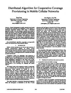
Figure 1: Flow of our ADAM approach Definition 5: A cluster agent CA ∈ Ag is an agent that is responsible for mapping operations within the cluster Ci . The cluster i agent is located in the processing element pC j where the index j of pj denotes that the cluster agent can be mapped to any PE of the cluster. The CA stores the information about the cluster that the agent is responsible for (see Table 1, 2). Definition 6: A global agent GA is an agent that stores the information for performing the mapping operations to a selected cluster. It stores information regarding the current usage of communication and computation resources for each cluster and this information is used for selection and re-organization of the clusters (see Table 1). GA is movable and the stored information is light-weight and easily recoverable (there are multiple instances of the global agents). Definition 7: The application mapping function is given by m : T � ti �→ nj ∈ N and the run-time mapping function mrun maps the instance of task graph set Gt at time t to HM P SoCN oC . Definition 8: A binding is a function b : T � ti �→ tpP E ∈ T ps, where T is the set of all tasks of an application and T ps is the set of the PE types that are used on the HM P SoCN oC . The function assigns each task ti of the CTG to a favorable type of PE. After the binding operation is completed, the tasks are allowed to be mapped only to PEs of the type given by the binding function b.
3. OUR ADAM SCHEME In the following we introduce our run-time Agent-based Distributed Application Mapping (ADAM) for a heterogeneous MPSoC with a NoC.
3.1 Some Definitions Definitions necessary to explain our run-time ADAM concept are described in the following: Definition 1: An application communication task graph (CTG) is a directed graph Gk = (T, F ), where T is a set of all tasks of an application and fi,j ∈ F is a set of all flows between connected tasks ti and tj annotated by the inter-task bandwidth requirement. Definition 2: A heterogeneous MPSoC architecture in a NoC platform HM P SoCN oC is a directed graph P = (N, V ), where vertices N is a set of tiles ni and vi,j ∈ V present an edge, the physical channel between two tiles ni and nj . A tile , ni ∈ N is composed of: a heterogeneous PE, a network interface, a router, local memory and a cache. Definition 3: A cluster is a subset Ci ⊆ N , where N is the set of tiles nj that belong to the HM P SoCN oC and a virtual cluster Cvi , is a cluster where there are no fixed boundaries to decide which tiles are included and which tiles are not. It can be created, resized and destroyed at run time. Definition 4: An agent Ag is a computational entity, which acts on behalf of others. The construction of an agent is motivated from [3] where agents are used for distributed network management. The properties of an agent in our scheme are: an agent (1) is a smaller task closer to the system, (2) it must do resource management, (3) it may need memory to store state information for the resources, (4) it must be executable on any processing element, (5) it must be migratable, (6) it must be recoverable, and (7) it may be destroyed if the cluster no longer exists. An agent-based mapping scheme provides a flexible framework for run-time mapping because it has the negotiation capability among the clusters distributed over the whole chip and it is not dependent on the design-time parameters (see above properties).
3.2 The ADAM Flow An overview of our ADAM system is presented in Fig. 1. The run-time mapping in our scheme is achieved by using a negotiation policy among Cluster Agents (CAs) and Global Agents (GAs) of a certain instance of time distributed over the whole chip. In Fig. 1 an application mapping request is sent to the CA of the requesting cluster which receives all mapping requests and negotiates with the GAs. There can be multiple instances of the GAs that are synchronized over time. The GAs have global information about all the clusters of the NoC in order to make decisions onto which cluster the application should be mapped to. Possible replies to this mapping request are: 1. When a suitable cluster of the application exists then the GAs inform the requesting source CA and the requesting source CA asks the suitable destination CA for the actual mapping of the application. 2. When no suitable clusters are found by the GAs then the GAs report the next most promising cluster where it is possible to map the application to after task migration which is negotiated between the GA and the CA to make this cluster suitable for the mapping. The number of iterations is a configuration parameter.
761
the flow, respectively bwreq is the required bandwidth of the flow, lat is the communication latency and RRtp is the resource requirement on each PE type that is needed for a task to ensure a successful execution. • The state information about all clusters are stored in a summarized format by the GAs (Table 1 and data object nhistc ). More detailed information is stored in the CA (Table 2). field req. memory short description tpP E log2 #T ps PE type id, #T ps= #of PE type q_tiles log2 #Cmax #Cmax = #of tiles in a cluster r_reqtot log2 #Cmax total comp. reso. req. by the PE type q_cl0 log2 #Cmax #tiles in res. req. class (0, n1 ] ... ... q_cln log2 #Cmax #tiles in res. req. class ( n−1 , 1] n
3. When neither a suitable cluster nor a candidate cluster for task migration are found, then the re-clustering concept is used. It tries to acquire PEs from the neighboring clusters (see Subsection 4.1). If the requirements are met after reclustering then the application may be mapped to that cluster. This step is iterated for a number of times specified by the configuration. If all the above-mentioned options do not lead to a successful mapping (the application and the system constraints are not met), then the mapping request is refused and reported to the requester. The requester waits until some resources are freed to proceed with the mapping. In the next section the detailed description of the runtime mapping algorithm using our ADAM concept is presented. Algorithm 1 Suitable cluster negotiation input: CT G, {nhistc [] | c is cluster} (a),(f) output: c, b[] (suitable cluster and binding) (f),(g) u(tp, t): the comp. res. req. when the task t is bound to tp (c) u[tp]: the total comp. res. req. for the PE type in CT G E(tpj , ti ): computation energy when task ti is bound to tpj (d) nloop : constant, num. of matching loop iterations 1: for all ti ∈ CT G do // min energy binding (d) & // thist calc. & summrz. u(tp) in CT G 2: b[ti ] = mintpj {E(tpj , ti ) = u(tpj , ti ) · (E[100] (tpj ) − E[0] (tpj )) + E[0] (tpj )} // initial binding, // min. energy (d) 3: u[b[ti ]] = u[b[ti ]] + u(b[ti ], ti ) // columns of res. // req. profile (c) 4: k = �u(tpj , ti ) · ncl � 5: thist[b[ti ], k] = thist[b[ti ], k] + 1 (e) 6: end for 7: sort thist by u[tp] desc 8: tpmax = maxtpj {u[tpj ]} 9: sort {c ⊆ N |c is a cluster} by uc [tpmax ] 10: for all c ⊆ N, c is a cluster do 11: sort nhistc by u[tp] asc (eq. (1)) 12: match thist and nhistc 13: store mismatch[c, iloop ] = (tpj , kmis , qnttsk,mis ) 14: if matched or iloop = nloop then 15: leave loop 16: end if 17: end for 18: if iloop = nloop then 19: for all c ⊆ N, c is a cluster, (init : iloop = 0) do 20: (tpj , kmis , qnttsk,mis ) = mismatch[c, iloop ] 21: move qnttsk,mis tasks with maxt {u[b[t]]} from tpj to another PE type with mintp {E(tp, tasks)} 22: match thist and nhistc 23: if not matched or iloop = nloop then 24: restore b[] to min energy binding; leave loop 25: end if 26: end for 27: end if 28: if not matched: find cluster and tasks to migrate 29: if not matched: find cluster and tasks to re-cluster 30: return b[], c
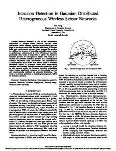
Table 1: Global agent: entry of the cluster PE type LUT • Energy Model: To make a binding decision (see Def. 8), the amount of energy consumption for different PE types at different resource requirement levels is needed. To explain the energy model we take an example from Fig. 2 (b), where for the PE type tp2 the energy consumption is specified by two values: tp2 : (4X, 12X) that means that each PE of type tp2 consumes 4 units of energy (static energy consumption) in a fixed time when it uses no processing resources and 12 units of energy when it consumes the complete PE resources and otherwise E = u · (E[100%] − E[0%] ) + E[0%] . • thist[] and nhistc [] are two data objects that store the resource requirement histograms within the local memory of the CAs and GAs, thist for the required resources for the tasks and nhistc for the actual PE resource usage status of the cluster c (i.e. Fig. 2 (e), (f)). Each entry thist[tp, k] gives the number of tasks of a given type that is part of resource , k ] and each entry nhistc [tp, k] requirement class ( k−1 ncl ncl gives the actual number of tiles of a given type in resource requirement class ( k−1 , k ]. ncl ncl • The output data is the selected virtual cluster where the application will be mapped to and the binding of the tasks to the PEs, ∀ti ∈ T : b(ti ) ∈ T ps (see Def. 8). t1 10
7 3
t2
t3
t5
11 t4
5
tp PE 1 2 3 4
E [0%] 2X 4X 1X 5X
E [100%] 11 X 12 X 17 X 21 X
task E [100%](tp 3)
(b) energy by resource req.
res. req. tp 1 tp 2 9 12 33 16 51 22 42 30 61 55
by tp PE tp 3 tp 4 17 8 39 15 49 21 45 20 46 21
tp PE resource req. by classes 1/5 2/5 3/5 4/5 5/5 1 1 0 1 15 1 1 1 1 2 2 2 2 5 4 5 5 3 3 2 2 4 4 4
(c) resource req. profile
(a) task graph energy task tp 1 tp 2 1 2.81 4.96 2 4.97 5.04 3 6.59 5.76 4 5.78 6.4 5 7.49 8.4
1 2 3 4 5
= 17 X
by tp PE tp 3 tp 4 3.72 6.28 7.24 7.4 8.84 8.36 8.2 8.2 8.36 8.36
tp PE 1 2 3 4
(f) PE availability in a cluster
resource req. by classes 1/5 2/5 3/5 4/5 5/5 1 1 1 1 0 0 1 0 0 0 0 0 0 0 0 0 0 0 0 0
(e) task comp. res. reqirements
t1 10
t2
t3
t5
11 t4
5 Legend PE type 1 PE type 2
(d) energy consumption/ min-energy binding
7 3
t1
task t1 7 flow, with bw
(g) binding
Figure 2: Suitable cluster and binding example The matching of the two data objects nhistc and thist is the heart of Alg. 1 and is given below in Eq. (1).
4. ALGORITHM FOR RUN-TIME MAPPING In this section we present our detailed algorithm of run-time Agent-based Distributed Application Mapping (ADAM) which has the following two components: (1) a cluster negotiation algorithm and (2) a mapping algorithm inside a virtual cluster.
ncl −1
∀i ∈ 1, .., ncl − 1 :
X
j=ncl −i
thist[tp, j] ≤
i X
nhistc [tp, j] (1)
j=1
In Fig. 2 we present an example of the cluster searching procedure. The task graph of an application that is requested to be mapped is shown in Fig. 2(a). The energy consumed by various PE types in different resource requirement levels is given in 2(b) and it is used to calculate the actual required energy consumption for every task on different types of PEs (see 2(d)). The resource requirements of the tasks is given in 2(c). Using the tables 2(c) and 2(d) the minimum energy binding for the tasks of the application is derived. Using the task binding, Fig. 2(e) shows the resource requirement profile to create a histogram corresponding to the data object thist[]. Fig. 2(f) presents the histogram nhistc [] for a cluster. In
4.1 Cluster Negotiation Algorithm Here we present our run-time suitable cluster negotiation algorithm (see Alg. 1). The algorithms (Alg. 1 and Alg. 2) have the following important input and output data objects: • The application CTG, G with required computational resource profiles for each task. G is given by a set of entries for each flow: entry = (idsrc , iddst , bwreq , lat, RRtp ). Here, idsrc and iddst are the id of the source and destination task of
762
Algorithm 2 Run-time mapping CT G: input data, application CTG mpng: output data, mapping of tasks to tiles tileLU T,clu : state of the physical network T ps ∈ tileLU T,clu : types contained in model tpP E : type of a tile’s PE, tpP E ∈ T psmodel rs_avail(tpP E ): gives the available computational resources of all PEs of the given type tpP E binding: ∀ti ∈ CT G : ∃b(ti ), b : see Definition 8 sorted: T ps, asc, by rs_avail(tpP E ) // sorting by // avail. of PE types 1: for all a ∈ T ps do 2: f a = {fij ∈ tg | bound(ti , a) ∨ bound(tj , a)} 3: sort(f a , desc, by bw_req(fij ∈ f a )) k ∈ f a do 4: for all fij 5: select ni� , nj � ∈ tileLU T,clu , for ti , tj by min(cmp ) 6: insert(ni� , nj � to mpng) 7: end for 8: end for 9: allocate(mpng); update(tileLU T,clu by mpng)
this example task 2 needs to be rebound to a new PE type to find a suitable cluster which has better energy consumption during the algorithm execution. Finally, Fig. 2(g) presents the new binding and the selection of the cluster. The complexity of our cluster negotiation algorithm is O(m + r · log r) where m is the number of tasks and r is the number of virtual clusters. Due to the low complexity, this part of our approach is suitable to be applied at run-time. Parent task
Cluster agent
Source tile
(1)Send a mig req
Destination tile
Connected tiles
(2)Freeze the connected tiles
(2)Freeze the source tile
(3)mig(tsk,c_txt_swt) (4)Succ_mig
(4)Succ_mig
(2)Freeze the destination tile (5)Release the freeze (5)Release the freezes
(6)/*done*/
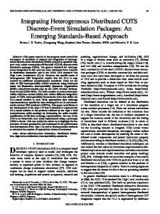
whenever the current instance of the mapping needs to be modified. The pseudo code of the run-time mapping algorithm inside each cluster is presented in Alg. 2. The input data is the CTG of the application and the model tileLU T,clu of the HM P SoCN oC that stores the current state of the used computation and communication resources of that particular cluster. The CTG contains the required energy consumption for each task to be executed on a particular PE type. The task binding is done in the cluster negotiation step with the GAs before the mapping step inside a virtual cluster. The CTG contains the communication costs for each flow fij between the tasks ti and tj . The tile-LUT tileLU T,clu contains each tile’s current computation resource usage, the type of the PE of this tile tpP E , and the current bandwidth usage for each link. The output (mpng) is the mapping of tasks to tiles of the network which is used to allocate the tiles physically on the network and to update the tileLU T,clu by the added application.
Figure 3: Task migration to support run-time application mapping In case a suitable cluster cannot be found in Alg. 1, it starts looking for the clusters which support task migration. Task migration2 as an integral part of our run-time mapping algorithm is demonstrated in Fig. 3. The parent task sends a migration request to the CA and upon receiving the request it freezes the source tile, tiles connected to the source, and the destination tile for successful and transparent migration. Then, the migration is performed with all local data within the executing task, the state of the task and even the modified binary of the task (the binary of the application may need to be changed to make it executable for different instruction set processors). The feedback is then provided to the CA. QoS reqr. not met
taking PEs from neighb. clusters no free PEs and no
requesting neighb’s left neighb’s for free PEs
no free PEs and no
requesting neighb’s left neighb’s for migration
req. neighb’s for least utilized PEs
10
t1
t2
Legend
7
t3
no free PEs reported and neighb’s left
take freed PE
take unoccupied PE
Re-clustering successful
Legend:
Start state End state
neighb’s left, PE not shared
map app
tp_i tp_1 tp_2 tp_3 tp_4 tp_5
no reclustering possible
Re-clustering failed find another cluster
a
f
d
t1
(b) tiles (part of cluster)
b e
t2 t3
c f
t5 t4
PE type 1 PE type 2
t1 7
PE type 3
avail_rs( tp_i) 1730 % 210 % 370 % 530 % 505 %
ord(tp_i) 5 1 2 4 3
task t1 flow, with bw
(c) tasks placed on tiles
flows 1-2 1-3 3-4 4-5
bw 10 7 5 11
(e) flows by PE types
(d) available computation resources
Figure 4: The re-clustering algorithm flow When the migration of tasks does not deliver a suitable cluster, then the re-clustering operation shown in Fig. 4 is invoked. First negotiation is done between neighboring clusters to see if there are some unoccupied PEs that can be given away to the requesting cluster. If no unoccupied PEs are available, the neighbors are requested to migrate tasks from some PEs to other PEs of that cluster without losing its performance and run-time constraints. If that is not successful either, then the neighboring cluster is requested for the least utilized PEs that may be shared with the requesting cluster.
4.2
c
e
(a) task graph
share PE
QoS reqr. met
b
d
5
t5 11 t4 no free PEs reported and neighb’s left
a
tasks cmp_req t1 30 % t2 25 % t3 29 % t4 40 % t5 38 % (f) required comput. costs
PE a b c d e f
res. in use 10 % 40 % 20 % 10 % 33 % 25 %
(g) current comp. resources in use by tasks on tiles
Figure 5: Run-time application mapping example To decide to which tile of a particular PE type a task should be mapped, a heuristics is used, described by the cost function c(t, n), for the selection of a tile nj for a given task ti . X c(ti , nj ) = α(D(nj )+bwt (nj )+RR(nj ))+β d(k)vol(k) k∈Tcon,m 1 #tilesclu
P
where, D(n) = l∈N d(n, l): D(n) is the average distance of a tile to all other tiles of the cluster, d(n, l) is the Manhattan distance between tiles n and l, Tcon,m is the set of all connected and mapped tasks ti , d(k) is the Manhattan distance between the mapped tasks, vol(k) is the communication between the connected tasks, RR(nj ) is the resource requirement of the PE that will be assigned for the task, and bwt (nj ) is the total bandwidth requirement of the tasks on the tile. In the following, Alg. 2 is explained using an example (see Fig. 5). In Fig. 5 (a) we present a task graph, whose tasks are grouped by the binding function (shown in different colors) in the earlier negotiation stage. In 5 (b) a part of the tiles of the current cluster is presented, 5 (g) shows the current resources in use of some of these
The Mapping Algorithm
Our run-time mapping algorithm inside a cluster managed by the CA is motivated by the static mapping algorithm presented in [12] as it is light-weight in terms of execution cycles and provides a near-optimal mapping solution. The given algorithm is executed once at design time. But for using the algorithm at run-time it needs to be modified to keep the current instance of the mapping. It is then executed in the background reacting to mapping requests 2 Details of task migration are not discussed in the scope of this paper. Our scheme uses the approach presented in [17]
763
1000000 (a) Mapping Computational Effort (Fixed cluster size)
8x8 NoC 16x16 NoC
ADAM (Our Scheme) centralized NN (app. from [6]) centralized MAC (app. from [6]) centralized PL (app. from [6])
100
10
1000 64
100
144
256
400
NoC Size [Tiles]
1024
2048
4096
ADAM (Our Scheme)
centralized MAC (app. from [6])
centralized NN (app. from [6])
centralized PL (app. from [6])
100000 X * Cycles
10000
(c) Mapping Computational Effort (1 Cluster)
1000000
32x32 NoC 64x64 NoC
1000 X * Cycles
X * Cycles
100000
(b) Mapping Components (ADAM)
10000
Comparison to Centralized Scheme [6]
preparation
match
rebind match
migration re-clustering mapping
10000
1000 64
100
Components
144 256 400 Cluster Size [tiles]
1024
2048
4096
Figure 6: Computation complexity of mapping compared to [6] 12 bits), and a connection input FIFO (5 × 18 bits). The additional monitoring events for our ADAM scheme are added on top of this existing monitoring infrastructure and therefore, it increases the size of the LUT and FIFO. Detailed description of the monitoring module is out of the scope of this paper.
tiles and 5 (f) presents the computational resource requirements for each task of the task graph. In this example the availability of the resources is presented by the ordered column in a table (Fig. 5 (d)). In Fig. 5 (e) we see the first set of flows f tp2 that connect PEs of PE type 2: {f12 , f13 , f34 }. The flows are sorted in a decreasing order according to their bandwidth requirements. The result of a successful mapping is illustrated in Fig. 5 (c). To achieve a mapping instance we iterate over the set of flows and select tiles where the previously un-mapped tasks connected by the flows will be mapped. Then the algorithm continues with the next set of flows f tp1 that are connected to PEs of type 1. The complexity of our mapping algorithm is O(m · log m + m · n) where m is the number of tasks and n is the number of tiles in a particular cluster. The complexity is low compared to the heuristics in [6] when it is used in a distributed manner. This fact is verified in the result section (see Fig. 6). field req. memory short description id log2 #N tile id, Def. 2 tpP E log2 #T ps type of tile’s PE (Def. 8) r_reqcomp log2 #Lv computation resource req. bwused communication bw. usage All directions log2 #Lv output port, e.g. North q_vc virtual channel quantity All directions max. #VCs output port, e.g. North
5.
RESULTS AND CASE STUDY ANALYSIS
We have evaluated our ADAM approach using different application scenarios: a robot application (Image Processing Line [18]), some multi-media applications, and applications from TGFF [10]. We show the performance in terms of execution time and the volume of the generated monitoring traffic and compare our results to state-of-the-art centralized approaches [6, 8, 19]. In addition, we compare our cluster-level mapping algorithm to an exhaustive offline mapping algorithm in order to see how far it is off from an optimum solution. In Fig. 6(a) we compare our approach to the centralized one [6]. We have partitioned our mapping computation into several steps shown in Fig. 6(b). The configuration parameters for this experiment are as follows: the average cluster size is 64 and the number of tasks is 48. In this experiment the number of cycles to check whether a task can be mapped to a tile is represented by “X” (it may differ depending on the instruction set). We consider that each task has to be checked for a possible assignment to each tile inside a virtual cluster while in the non-clustered approach the tiles of the whole NoC have to be considered. Therefore, our approach can reduce the mapping computation complexity e.g. on a 32x64 system we have an approx. 7.1 times lower computational effort compared to the simple nearest-neighbor (NN) heuristics proposed in [6]. Fig. 6(c) shows that our approach scales in the same way as the non-clustered architecture when we do not consider the clustering approach in our algorithm.
Table 2: Fine-grained tile information inside each cluster agent We study which data objects are needed by the mapping algorithms and what kind of filtering mechanism may be used to reduce the amount of data stored in the GAs. The state information about the tiles and the links of the HM P SoCN oC have to be stored by agents on different levels (GAs, CAs). CAs will need the fine grained information about the cluster to provide the distributed mapping shown in Table 1 and 2. Table 1 contains the histogram of computational resource requirements of the PEs. For each cluster there is also an instance of this PE type LUT stored in the GA. The filtering process is as follows: (1) using the “raw” data from the data object described by Table 2, (2) calculating the information stored in data object described by Table 1, and (3) transmitting this data from the CAs to the GAs. Another data object stored within each CA is the variable mpng, a LUT shown in Alg. 2. The structure of each entry within this LUT consists of the id of the source task, destination task, assigned tile, application, resource requirements for execution, communication volume, and the required latency. The run-time flexibility of the mapping algorithm compared to a design-time static mapping algorithm comes at some extra penalties: near-optimal mapping solution (Fig. 8), extra computation at run-time (Fig. 6(b)), additional traffic to collect information about the current state of the chip (Fig. 7), and finally monitoring infrastructure implemented in each router to collect information about the current state of the MPSoC. Monitoring hardware is already an integral part of our adaptive on-chip communication scheme presented in [11]. The monitoring module implemented for our adaptive router requires 46 slices on a XILINX Virtex2 FPGA [21], an LUT (number of entries × 26 bits), an event input FIFO (5 ×
100000
ADAM 8x8 (our scheme) centr. 8x8 (app. from [7,19]) distr. 8x8 ADAM 32x32 (our scheme) centr. 32x32 (app. from [7,19]) distr. 32x32
ADAM 64x64 (our scheme) centr. 64x64 (app. from [7,19]) distr. 64x64
10000
[Kbytes]
Amount of Data by Each Instance of Mapping
Traffic produced to collect the current MPSoC state 1000000
1000
100
10
1 10
20
40 100 Application Size [Tasks]
200
500
Figure 7: Our ADAM approach compared to approaches [7,19] Fig. 7 demonstrates the advantage of our approach when we consider the communication volume generated by the monitoring module of the router needed by the mapping algorithm. We compare our cluster-based distributed approach to a centralized approach [8, 19] and a fully distributed approach (each tile acts as an individual cluster). The experimental setup is as follows: number of classes and PE types are 16, resource requirement encoding requires 1 Byte, task id encoding requires 4 Bytes, number of tasks encoding requires 4 Bytes, and bandwidth encoding requires 1 Byte of memory space. To calculate the mapping traffic produced by our
764
approach we need to break down the communication into the following parts: (1) transmission of the task histogram thist[] to the GA, (2) transmission of the task graph to the CA of the suitable cluster, (3) reporting the cluster state to the CA, and (4) transmission of the cluster state to the GA. The experiment shows that our approach has noticeable advantages in reducing the amount of communication volume (10.7 times lower on a 64 × 64 NoC) caused by the mapping when the HM P SoCN oC has many tiles. Communication Cost [MB/s]
14000 12000 10000
Resulting Communication Volume after Mapping ADAM (Our Scheme) Exhaustive optimization for mapping resulting mapping solution using ADAM
8000 6000 4000
[3] [4]
Mapping Instance of the Robotics Application Gauss 2
Input
Grad
RGB 2 HSV
Gauss 1
Post
Shirt Filter
Skin Filter
Output
[6]
2000 0
[5]
[7] MPEG
Image VOPD MWD Processing Line ( x 1/100 MB/s )
Applications
[8]
Figure 8: Comparing ADAM to exhaustive off-line mapping algo. In Fig. 8 we present a comparison of the suitability of our clusterlevel mapping algorithm. It shows that our approach does not produce optimum results as they can be produced by the off-line exhaustive algorithm which requires a far higher computational effort. But relative to the consumed computation effort our approach provides a reasonable near-optimal solution. The communication volume serves as the optimization criteria for the mapping algorithm (it reduces the communication related energy consumption [15]), and we found on an average a deviation of a mere 13.3% compared to the exhaustive mapping algorithm. To make the comparison to the off-line exhaustive mapping algorithm realistic, a homogeneous tile has been considered. The near-optimal result can be used for the run-time task mapping as this result may be traded-off with the adaptivity and the lower computational effort. We have also evaluated our mapping algorithm by means of a robot application presented in [18]. We found in our algorithm the near optimal communication volume to be 120.1 MB/s whereas, in the exhaustive off-line mapping algorithm it can be reduced to 106.9 MB/s. The result is acceptable as we are doing it at run-time using a heuristic algorithm and consuming 2 times lower execution cycles compared to NN heuristics. The Image Processing Line application takes only 11241 × X cycles using our ADAM algorithm orthogonal to any instruction set processor compared to NN heuristics (takes 20480 × X cycles) proposed in [6] on a 32 × 64 NoC. Therefore, we observe that our run-time agent-based distributed application mapping approach reduces the overall monitoring-traffic compared to a centralized mapping scheme and requires less execution cycles compared to a non-clustered centralized approach.
[9] [10] [11]
[12]
[13]
[14] [15]
[16]
6. CONCLUSION We have introduced the first scheme for a run-time application mapping in a distributed manner using an agent-based approach. We target adaptive NoC-based heterogeneous multi-processor systems. The ADAM scheme generates 10.7 times lower monitoring traffic compared to a centralized scheme like the ones proposed in [8, 19] in a 64 × 64 NoC. Our scheme also has a smaller number of execution cycles compared to a non-clustered centralized approach. In our experiments we achieve on an average 7.1 times lower computational effort for the run-time mapping algorithm compared to the simple nearest-neighbor (NN) heuristics proposed in [6] on a 64 × 32 NoC. The flexibility of a run-time adaptive mapping, a 7.1 times lower computational effort and a 10.7 times lower monitoring traffic counterbalance the optimization result compared to an optimized run-time centralized mapping algorithm.
7.
[17]
[18]
[19]
REFERENCES [20]
[1] L. Benini and G. De Micheli. “Networks on Chips: A new SoC paradigm”. IEEE Computer, 35(1):70–78, 2002. [2] S. Bertozzi, A. Acquaviva, D. Bertozzi, and A. Poggiali. “Supporting task migration in multi-processor systems-on-
[21]
765
chip: a feasibility study”. DATE’06: Proc. of the Conf. on Design, Automation and Test in Europe, pages 15–20, 2006. A. Bieszczad, B. Pagurek, and T. White. “Mobile agents for network management”. IEEE Comm. surveys and tutorials, 1(1):2–9, 1998. S. Borkar. “Thousand core chips – A technology perspective”. DAC’07: Proc. of the 44th annual Conf. on Design Automation, pages 746–749, 2007. H. Broersma, D. Paulusma, G. J. M. Smit, F. Vlaardingerbroek, and G. J. Woeginger. “The computational complexity of the minimum weight processor assignment problem”. WG’04: Proc. of the 30th int. Workshop on Graph-theoretic concepts in computer science, pages 189–200, 2004. E. Carvalho, N. Calazans, and F. Moraes. “Heuristics for dynamic task mapping in NoC-based heterogeneous MPSoCs”. RSP’07: Proc. of the 18th IEEE int. workshop on Rapid System Prototyping, pages 34–40, May 2007. J. Chan and S. Parameswaran. “NoCGEN: A template based reuse methodology for networks on chip architecture”. VLSID’04: Proc. of the 17th int. Conf. on VLSI Design, pages 717–720, 2004. C.-L. Chou and R. Marculescu. “Incremental run-time application mapping for homogeneous NoCs with multiple voltage levels”. CODES+ISSS’07: Proc. of the 5th IEEE/ACM int. Conf. on Hardware/software Codesign and system synthesis, pages 161–166, 2007. W. J. Dally and B. Towles. “Route packets, not wires: Onchip interconnection networks”. DAC’01: Proc. of the 38th Conf. on Design Automation, pages 684–689, 2001. R. P. Dick, D. L. Rhodes, and W. Wolf. “TGFF: Task graphs for free”. CODES/CASHE’98: Proc. of the 6th int. workshop on Hardware/software Codesign, pages 97–101, 1998. M. A. A. Faruque, T. Ebi, and J. Henkel. “Run-time adaptive on-chip communication scheme”. ICCAD ’07: Proc. of the 2007 IEEE/ACM int. Conf. on Computer-aided design, pages 26–31, 2007. A. Hansson, K. Goossens, and A. Rˇadulescu. “A unified approach to constrained mapping and routing on networkon-chip architectures”. CODES+ISSS’05: Proc. of the 3rd IEEE/ACM int. Conf. on Hardware/software Codesign and system synthesis, pages 75–80, 2005. J. Henkel, W. Wolf, and S. Chakradhar. “On-chip networks: A scalable, communication-centric embedded system design paradigm”. VLSID’04: Proc. of the 17th int. Conf. on VLSI Design, pages 845–851, 2004. P. Horn. “Autonomic computing: IBM’s perspective on the state of information technology”. IBM Corporation, 2001. J. Hu and R. Marculescu. “Exploiting the routing flexibility for energy/performance aware mapping of regular NoC architectures”. DATE’03: Proc. of the Conf. on Design, Automation and Test in Europe, pages 10688–10693, 2003. T. Lei and S. Kumar. “A two-step genetic algorithm for mapping task graphs to a network on chip architecture”. DSD’03: Proc. of the Euromicro symposium on Digital Systems Design, pages 180–189, 2003. V. Nollet, T. Marescaux, P. Avasare, D. Verkest, and J.-Y. Mignolet. “Centralized run-time resource management in a network-on-chip containing reconfigurable hardware tiles”. DATE’05: Proc. of the Conf. on Design, Automation and Test in Europe, pages 234–239, March 2005. P. Azad, A. Ude, T. Asfour, G. Cheng, and R. Dillmann. “Image-based markerless 3D human motion capture using multiple cues”. Proc. of the int. workshop on Vision Based Human-Robot Interaction, 2006. L. Smit, G. Smit, J. Hurink, H. Broersma, D. Paulusma, and P. Wolkotte. “Run-time mapping of applications to a heterogeneous reconfigurable tiled system on chip architecture”. FPL’04: Proc. of the IEEE int. Conf. on Field-Programmable Technology, pages 421–424, 2004. P. Smith and N. C. Hutchinson. “Heterogeneous process migration: The Tui system”. Software – Practice and Experience, 28(6):611–639, 1998. Xilinx. ”Virtex2 datasheets”. http://www.xilinx.com/.