360
IEEE TRANSACTIONS ON VISUALIZATION AND COMPUTER GRAPHICS,
VOL. 8,
NO. 4,
OCTOBER-DECEMBER 2002
Adding Support for High-Level Skeletal Animation Francisco J. Seron, Member, IEEE, Rafael Rodriguez, Eva Cerezo, and Alfredo Pina Abstract—We hereby present a data structure specially geared toward the definition and management of synthetic actors in real-time computer graphics. The relation between our proposed data structure and the Silicon Graphics API Performer1 makes its implementation possible on a low-cost real-time platform thanks to current accelerating cards. We demonstrate how our data structure is used to generate motion by means of two different applications. Both of them make use of direct (DK) and inverse kinematics (IK) and may use motion capture. ARTgraph is a development environment devoted to the creation of high-quality real-time 3D-graphics applications (basically, 3D games) and the ALVW system is a general platform that provides and coordinates a sensing-analysis-acting loop to provide behavior for synthetic actors in their own scenario. The aim of this paper is to contribute to the standardization process of multiplatform synthetic actor programs or libraries. Index Terms—Synthetic actors, real-time, computer animation, Performer1, API.
æ 1
INTRODUCTION
T
HE
need for synthetic actors [1] in simulation environments is obvious: In a driving simulation, streets and cars are necessary, but so are pedestrians and car-instructors; historical reconstructions need virtual guides, architectural environments need characters to inhabit them, etc. Increases in computational power and control methods enable the creation of 3D virtual characters even for real-time interactive applications. In spite of this, current real-time simulation systems direct their effort toward the visualization of static environments or environments with objects that feature simple movements such as cars, planes, etc. The complex articulated structures that define a synthetic actor raise different issues that need to be addressed using specific data structures and management methods. When we speak about synthetic actors, we do not mean only human-like actors. Actually, this is a wide concept that includes any kind of complex articulated structure with a natural or artificial appearance. Thus, a machine, a robot, an animat, or a human-like actor, a plant moved by the wind, or a deformable metallic mainframe, can be considered a synthetic actor. There are several methods for classifying synthetic actors [2], [3], [4]. One of them is to use the nature of the information required for controlling actors’ motion and behavior. There are two primary mechanisms to specify motion and behavior for a synthetic computer-generated character:
. F.J. Seron and E. Cerezo are with the Advanced Computer Graphics Group (GIGA), Computer Science Department, Technical School of Engineering, University of Zaragoza, C/ Maria de Luna, 1, E-50015 Zaragoza, Spain. Email: {seron, ecerezo}@posta.unizar.es. . R. Rodriguez is with Brainstorm Multimedia, Valencia, Spain. E-mail:
[email protected]. . A. Pina is with the Mathematics and Computer Science Department, Public University of Navarra, Campus de Arrosadia s/n, E-31006 Pamplona, Spain. E-mail:
[email protected]. Manuscript received 7 July 2000; revised 5 Mar. 2001; accepted 27 Sept. 2001. For information on obtaining reprints of this article, please send e-mail to:
[email protected], and reference IEEECS Log Number 112411.
Replication mechanisms that reproduce the motion or behavior of a real actor. . Modeling mechanisms where the motion and behavior are based on an algorithmic approximation. Several techniques can be used to model or replicate motion and behavior. The final goal of current leading animation systems is to create free synthetic actors in nonpredictable virtual environments. These systems make use of different kinds of mechanisms: perception-action systems [5], [6], intelligent agents-based systems [7], [8], [9], neural networks-based systems [10], action-selection mechanisms [11], [12], [13], [14], [15], [16], cognitive modeling [17], [18], and other techniques [19], [20], [21]. For completeness, in Table 1, important research groups working on innovative areas in computer animation are shown. In any case, it does not try to be exhaustive; a more comprehensive and deeper survey can be found in [4]. Regardless of the chosen method, working in real-time requires certain “additions,” such as efficient storage, to optimize data access and to avoid unnecessary computation. Real-time computer graphics and data structures specially geared toward the definition and management of synthetic actors are mature areas of computer science. There are a number of previous efforts on which our work relies to a certain degree. We have divided them into two different groups: First of all, we revise current general purpose graphic APIs and, then, we present two relevant experiences trying to standardize data structures for human bodies animation. Despite vast differences between computer graphics applications, today there is one general commonality in the description of the scene structure, the data structure called “scene graph.” Several applications programming interfaces (APIs) have been built to avoid the difficulties involved in programming computer graphics at such a low level. The scene graphs are usually designed to optimize the graphics rendering pipeline and, especially, the culling procedures [22]. Although different applications may use .
1077-2626/02/$17.00 ß 2002 IEEE
SERON ET AL.: ADDING SUPPORT FOR HIGH-LEVEL SKELETAL ANIMATION
361
TABLE 1 Different References of Research Groups Currently Working on Innovative Areas of Computer Animation (Alphabetically Ordered)
different scene graph libraries, the underlying features of each scene graph are generally quite similar and reasonable mappings between them can be made. The most widely used are: .
.
.
.
SGI’s Open Inventor1 (http://www.sgi.com/ software/inventor/tech_info.html): very flexible, extensible scene graph API for rapid prototyping, but not very quick; provides many interaction techniques [23]. SGI’s Performer1 (http://www.sgi.com/software/ performer/tech_info.html): monolithic scene graph API geared toward performance (visual simulation, guaranteed update times, etc.). The principal design goal is to allow applications developers to get maximum performance from 3D graphics platforms which feature multiple CPUs and support an immediate-mode rendering library [24]. SGI’s OpenGL1 Optimizer (http://www.sgi.com/ software/optimizer/): toolkit geared toward the CAD/CAM market; Optimizer itself is not a scene graph API, but works on a scene graph API specially optimized to handle large models [25]. SUN’s Java3D (http://java.sun.com/products/ java-media/3D): platform independent scene graph
.
.
.
API. Java 3D introduces some concepts not commonly considered part of the graphics environment, such as 3D spatial sound [26]. VRML 97 (Virtual Reality Modeling Language, International Standard ISO/IEC 14772) (http:// www.web3d.org/): contains hierarchically grouped geometry to provide audio-visual representation of objects; whereas Java 3D, Performer1, or Optimizer pursue the highest performance, VRML 97 pursues the highest flexibility [27]. Microsoft’s Direct3D Retained Mode: basic scene graph API with animation support (http:// www.microsoft.com/directx/dxm/help/d3drm/); not so widely used. Others: there are some other scene graphs, such as RMScenegraph (http://www.r3vis.com/RMScene Graph), a general purpose OpenGL-based scene graph API currently available for Unix/Linux/ Win32 [28]. Or Openscenegraph, a cross-platform C++/OpenGL library (currently supported platforms are IRIX, Linux, and Windows) for real-time visualization, with uses ranging from visual simulation, scientific modeling, and virtual reality to games (http://www.openscenegraph.org).
362
IEEE TRANSACTIONS ON VISUALIZATION AND COMPUTER GRAPHICS,
Regarding standardization, great efforts have been made in the field of human animation due to its significance. In particular, two important standardization projects are being developed: The VRML Humanoid: The VRML Humanoid is a proposal for the definition of a standard representation of human beings in VRML97 developed by the Humanoid animation working group (http:// h-anim.org) [29]. Their goal is to allow a character created with a specific tool to be animated by different independent applications. It totally fixes the number and topology of human joints, as well as the names that have to be used to access them. A VRML file containing a human specification uses five kinds of specific nodes. Joint nodes, for joint parameters, Segment nodes, for describing the body part associated with the joint, Site nodes that define positions relative to the segments that could be used as auxiliary points to attach cloths or jewels, and a Humanoid node to store general characteristics such as the author or copyright and which contains references to all the Joint and Segments nodes for easy access. The standard file may also contain keyframing sequences or Script nodes to access the joints directly via different motion control methods. . The MPEG4 Body Model: The MPEG-4 standard will include coding of integrated audio and visual data, both synthetic and natural, in bandwidth and storage-capacity-limited systems with real-time synchronization and scalability [30]. The MPEG4 Body model proposal from the MPEG-4 Face and Body Animation Ad Hoc Group (FBA) is based on the EPFL-LIG (Computer Graphics Lab (LIG) at the Swiss Federal Institute of Technology (EPFL) in Lausanne (http://ligwww.epfl.ch/) human model [31]. One of the more relevant aspects of this format is the codification of facial and bodily 3D human characters, as well as their synchronization with natural or synthetic voice. Facial and corporal animation is controlled independently. MPEG-4 does not standardize the geometrical models for the face or the body, but the parameters that can be used to personalize and animate both of them in real-time. Standard face and body anthropometric parameters together with those concerning facial expression and bodily posture are set forth. An MPEG-4 FBA-compliant decoder is assumed to have a default body model. Body definition parameters (BDPs) allow this local model of the receiver site to be customized by a particular body model. A set of body animation parameters (BAPs) that contain the joint angles connecting different body parts is used to modify the posture of the virtual body during animation. In the same way, facial definition parameters (FAPs) are used to characterize the synthetic face, whereas facial animation parameters (FAPs) control its animation. The aim of this paper is the definition of data structures specially designed to move real-time synthetic actors, not only human-like actors, in sophisticated computer anima.
VOL. 8,
NO. 4,
OCTOBER-DECEMBER 2002
tion applications that can be easily integrated within any animation system. The structure of the article is as follows: Section 2 introduces the new nodes in a scene graph context. Sections 3 and 4 describe the Skeleton and Actor nodes, respectively. Section 5 discusses implementation using Performer1. Section 6 presents two systems where the new data structure has been used. Finally, in Section 7, some conclusions are outlined.
2
THE SCENE GRAPH
AND THE
NEW NODES
As previously pointed out, current scene graphs are usually geared toward the visualization of large static objects stored in huge databases, such as terrain, buildings, etc., or the visualization of objects with simple movements, i.e., vehicles: Their nodes are not suitable for defining and managing scenes involving several synthetic actors. In this paper, we present two new types of nodes specially oriented to the definition and management of synthetic actors in real-time computer graphics. These selfdependent nodes are called actor and skeleton nodes. They attempt to make the capability of providing the user with high-level control over the actors compatible with a lowlevel management task that reduces the high computational cost of these kinds of structures. The actor node functions as the root node of the complex articulated structure comprised of several skeleton nodes (see Fig. 1). Each skeleton node plays the role of an actor’s joint, i.e., a shoulder, an elbow, a neck. The posture of an actor at a specific time depends on the affine transformation applied by the skeleton nodes to the scene graph. The transformation applied by each skeleton node is controlled by a set of variables, corresponding to the degrees of freedom stored in the corresponding actor node (not in the skeleton node). The actor node contains a list with the parameters that control the posture and the skeleton nodes have access to this list whenever they want to know the current values of these parameters. In this way, each modification of the actor’s posture is brought about by modifying the values of the parameters stored in this actor node’s list. This kind of relationship between actor and skeleton nodes is not very common in a scene graph; usually, each node’s data are isolated from those of the other nodes. However, such a relationship makes the hierarchical complexity of the synthetic actor transparent to the user that only has to perform high level operations in the actor node.
3
SKELETON NODES
Skeleton nodes are a special type of nodes capable of storing the information needed to define the actor’s topological structure as well as the information associated with the joint points belonging to the actor. Each of an actor’s joint points can store information relative to several degrees of freedom (dofs). It is common in 3D animation to define articulated structures using two types of elements: segments and joints. The former are used to represent rigid structures such as bones and the latter the joints between them, as depicted in Fig. 2. In spite of the visual intuitiveness of this model, it is not fully adequate for integration, as it stands, as nodes
SERON ET AL.: ADDING SUPPORT FOR HIGH-LEVEL SKELETAL ANIMATION
363
Fig. 1. Diagram of the articulated structure of a simplified human actor and his corresponding scene graph representation based on actor and skeleton nodes.
inside a scene graph. In fact, it is only necessary to store the relations of interdependence among joints as well as the affine transformations applied to each of them. The role of the joints is clear: They contain the information regarding the degrees of freedom. However, the segments’ role does
not have a direct interpretation in the nodes’ model. Our goal is to integrate virtual actors inside a scene graph for real-time applications, so hierarchical representation should be as simple as possible. One way of obtaining this simplicity is to avoid the creation of a segment node if it proves to be possible. Therefore, a few conclusions about segments can be established: A segment is directly dependent on a single joint. Any joint has at least one dependent segment, even though it may have more than one. . Segments are used to define the gap between two joints. That means that a segment works as an offset between the reference systems of two joints. . A segment acts as an interface graphic element referred to a joint. Usually, the values of a joint are changed by selecting one of the segments directly linked to it. As we can see, in essence, a segment has two basic functions: It applies an offset to a joint, indicating the relative position of this joint regarding the higher level joint, and it is an interface element for the joints that directly depend on it. This double role is the rule in the majority of segments, though some only act as offsets and others are only used as interfaces (see Fig. 3). Taking into account the above considerations and aiming to reduce the number of nodes necessary to describe a synthetic actor, we have defined a unique structure (node), called skeleton, which stores all the information concerning the segments and joints in an actor’s skeletal hierarchy. The skeleton node works as a storage structure for all the information regarding an articulated part of an actor. Specifically, it stores the following information: . .
Fig. 2. Traditional representation of a human leg by means of segmentjoint pairs and corresponding scene graph representation of hypothetical segment and joint nodes.
364
IEEE TRANSACTIONS ON VISUALIZATION AND COMPUTER GRAPHICS,
VOL. 8,
NO. 4,
OCTOBER-DECEMBER 2002
Fig. 3. Segment nodes and their mission as offset and interface elements.
.
. .
An offset that represents spatial differences between the reference system of the father node and the reference system of the articulation this node belongs to. An articulation point that stores the information regarding the degrees of freedom. An auxiliary element that acts as an interface to select and modify the current values stored in the joint point.
In Fig. 4, the previous example has been redefined using this new type of node. The different constituent elements of a skeleton node are also shown.
3.1 Skeleton Offset Usually, the joint point of a skeleton node will be located in a spatial point different to its father node’s joint point. This distance between both coordinate systems is called offset. The difference between the joint points of two skeleton nodes is understood as a translation matrix from the father skeleton
Fig. 4. Representation of a human leg by means of skeleton nodes. Constitutive elements of a Skeleton Node and Scene Graph representation of the human leg.
SERON ET AL.: ADDING SUPPORT FOR HIGH-LEVEL SKELETAL ANIMATION
node’s relative coordinate system to the coordinate system of the son node. Besides, some joints’ coordinate system have the same orientation as their father node’s coordinate system, i.e., the wrist regarding the elbow or the elbow regarding the shoulder. However, other joints have a very different orientation from their father joint; the ankle, for example, has a very different orientation than the knee. This is why it is necessary to use a rotation matrix that stores the orientation differences between a joint and its father joint.
3.2 Skeleton Articulation Point As already mentioned, the main purpose of the skeleton node is to store the affine transformations caused by the modification of any degree of freedom of the joint in this node. However, the different programs focusing on synthetic actors’ design have different criteria. Some impose a single degree of freedom per node, others distinguish between rotational joints and translational joints, and still others have different kinds of joints based on an anatomical model (single degree of freedom joints, kneecaps with two or three degrees of freedom, etc.). The solutions proposed for this problem are varied, but, basically, they are all focused on topological description, as well as on interface possibilities, without considering the efficiency of these joints in a real-time application. The skeleton nodes also take these facts into account and are designed for real-time uses. We have set down the following guidelines to fix the information to be stored inside the skeleton nodes: All the information has to be stored inside a single skeleton node in order to avoid unnecessary increase in the amount of nodes in the hierarchy. . This model focuses on organic-like actors’ management, but has to be able to manage other articulated mechanisms. . Efficiency in running time is a priority, although this implies that working with data structures will not be as comfortable as in traditional 3D animation programs. Following these criteria, we have chosen a type of node containing four degrees of freedom: Three of them contain the rotational information corresponding to rotations in the three local axes X Y Z and one of them contains the translation information (along X-axis). Therefore, processing of skeleton node information implies the creation of transformation matrices corresponding to the spatial offset of the preceding skeleton node, the rotation offset, the rotational dof around the Y-axis, the rotational dof around the Z-axis, the rotational dof around the Y-axis, and, finally, the translational dof along the X-axis. A global matrix skl_m is then calculated by multiplying the former matrices in the order in which they appeared. .
3.3 Strategies for Computational Cost Reduction These are the strategies used to improve the computational cost of managing the skeleton nodes: .
A transformation matrix will only be created if the corresponding dof has been activated to avoid this time-consuming process.
365
All the offset transformations will be accumulated in a single matrix (offset_m) owing to the fact that once the definition of a skeleton node is finished, its rotation and translation offset values remain fixed. We are assuming that the values of all skeleton nodes are modified in each frame. But, this is not usually the case. For instance, a person who is typing modifies the position of his/her fingers and eyes, but perhaps his/her legs and backbone remain still. As they remain in the same state, it would be unnecessary to recalculate their matrices. In order to consider this situation, an updated field has been included in the data structure to indicate whether the values of the joint must be recalculated or not. Each time the node skeleton is modified, the global matrix skl_m is recalculated. Besides, in certain circumstances, it may be advisable not to visualize the geometry of the entire object. For instance, an actor could be a car driver whose legs are hidden by other objects. Therefore, it would not be necessary to process and draw any node used in the definition of the actor’s legs, be they skeleton nodes or other types of nodes. To deal with this kind of situation, the skeleton node includes a hide flag that signals the drawing algorithms not to go on drawing the nodes controlled by this skeleton node. .
4
ACTOR NODES
The actor node is in charge of positioning the actor within the scene. It establishes the coordinate reference system for the ensemble of joints that constitutes the actor. Concerning the scene graph, this node is the father node of the rest of the actor’s nodes which makes access to the set of skeleton nodes that integrate the actor’s articulate structure easy.
4.1
Positioning the Synthetic Actor in the Scene by Means of the Actor Node Only three translations and three rotations are necessary to define the position of an actor in 3D space. But, this model, which suffices for traditional 3D animation programs, has its shortcomings when defining actors for real-time programs. We suggest the use of two groups of transformations: The first one defines the position of the reference point, which may be considered as the center of mass of the actor, although it can be used for other purposes. The second one defines the position of the skeleton’s root, a fixed point located in the actor’s bone structure considered as the father node of the rest of the skeleton’s nodes; for example, the lower point of the backbone in a human being. For instance: Suppose we have a bird flying in a circular trajectory. The skeleton root would be placed at the joint point between the backbone and the coxa. The flapping cycle causes minor displacements of this point in the vertical axis and small changes in its orientation. An observer moving parallel to the bird’s trajectory would see only these movements. In addition to these movements, the bird describes a curved trajectory in space. This means that, at the same time, the center of mass is suffering modifications in position and orientation. Although the global trajectory of the bird can be described by way of one set of transformations, it is very useful to divide it in two groups. The first one, called pretransformations, defines
366
IEEE TRANSACTIONS ON VISUALIZATION AND COMPUTER GRAPHICS,
VOL. 8,
NO. 4,
OCTOBER-DECEMBER 2002
Fig. 5. Positioning a human actor in the scene by means of pretransformations and posttransformations. Different positions of an actor’s reference point.
the position of the reference point (the center of mass) of the actor in the scene and, in this case, it would be useful to describe the circular trajectory of the bird within the scene. The second one, called posttransformations, defines the position of the actor skeleton’s root regarding the reference point and it would be useful to describe the cyclical movement during flight (see Fig. 5). The division of the actor’s transformations in two groups fulfills two basic functions: The use of the concept of center of mass of the actor during its movement. . The definition of an offset between the skeletons’ root of the actor and an appropriate point to place the actor in the scene. This is the secondary role of the reference point. For instance, in the case of an actor who is standing up, the reference point can be a point on the floor centered between the feet. In Fig. 5, examples of useful reference points can be seen. .
4.2
Strategies of Computational Cost Reduction when Processing Actors It is possible to improve the efficiency in the management of the actor’s nodes if we generate a matrix containing the results of the pretransformations (named pretr_m). In the same way, it is possible to define the matrix posttr_m to store the result of multiplying all the matrices related with posttransformations. These two matrices could be joined in a single matrix that contains the whole transformation applied by the actor node. Storing the information of the pretransformations and posttransformationsinside the matrices pretr_m and posttr_m, as well as storing the whole
transformation in actor_m, can drastically decrease the calculations associated with an actor node. Although the values stored in the matrices of an actor node should be updated with a high periodicity (about 25 times per second), normally, the stored values do not change from one frame to the next and, therefore, updating them is unnecessary. In order to avoid efficiency losses due to these unnecessary updating operations, the actor node includes the flags pretr_m_updated, posttr_m_updated, and actor_ m_updated. To understand the use of these flags, let’s consider an example. A skater is sitting on the side of the ice rink; because of the static position pretr_m_updated, posttr_m_updated flags would be TRUE. He then stands up and begins to perform static warm-up exercises. This action implies that pretransformations do not change because the position of the skater does not change, but posttransformations would change to describe the movements of the exercises: posttr_m_updated flag would now be FALSE. After this, he begins to move forward with increasing speed: This movement would imply changes in both matrices, so pretr_m_updated and posttr_m_updated flags would now be set to FALSE. Finally, he stops accelerating and moves with a constant speed in inertial movement gliding over the ice; in this case, only the pretransformation should be modified: pretr_m_updated would be FALSE. Usually, the content of the actor_m_ updated flag is the result of the Boolean operation AND between the other two flags. However, the user can block the calculus associated with the actor node in specific circumstances.
SERON ET AL.: ADDING SUPPORT FOR HIGH-LEVEL SKELETAL ANIMATION
367
Fig. 6. Relationship between actor and skeleton nodes and the high level lists.
4.3 Actor Nodes and High-Level Interface The basic role of the actor node is to be the father node of the entire virtual actor’s hierarchy. The actor node places the actor in the scene. A secondary and useful role of this node is to encapsulate all the actions performed on the virtual actor; in other words, to keep the hierarchical complexity of the actor from the user. There are basically two types of low-level operations the user can perform on an actor: To ask for the spatial position of a specific joint. To modify the value of any degree of freedom of a joint. The operations involved in accessing the degrees of freedom are simple because it is the actor node that contains these values by means of two lists. The most common operations with virtual actors involve modifications in the values of their degrees of freedom. This is why the first list, the l_conf list, stores the values of the degrees of freedom of its skeleton nodes: It enables direct modification without accessing their skeleton nodes, thus avoiding all the graph traversal. Nevertheless, in certain cases, it is also necessary to access other pieces of information stored in the skeleton nodes (i.e., to know their positions in case of collision detection). For this reason, the actor node includes a second list (l_skelets) which allows easy access to the skeleton nodes, avoiding graph traversal once more. Fig. 6 shows these two lists and their relationship with the actor and skeleton nodes. Using these lists, the user performs . .
operations easily on the virtual actors without knowing the node structure of the mainframe. Clearly, an update in the actor node would have consequences in the state of the skeleton nodes related to the actor node.
5
PERFORMER1: A REAL-TIME PLATFORM
Performer1 2.4, as has been mentioned before, is a Silicon Graphics API, based on OpenGL1, oriented to real-time simulation and other interactive graphics. At present, a Linux version is available in Red Hat packages that makes use of Mesa 3.3 (OpenGL1 1.3 implementation for Linux) and Lesstif (free version of Motif). Therefore, thanks to current accelerating cards, nowadays it can be used in lowcost platforms such as a personal computer with enough memory (512Mb minimum) and high processing power. The relation between our proposed data structure and Performer1 is straightforward. The actor node corresponds to a pfDCS type node. A pfDCS is a branch node that represents a dynamic coordinate system used to apply an initial transformation to a node and to change the transformation during execution. It is very well adapted to show the object’s motion and to articulate moving parts. User slots can be added to it by using procedures available to all kinds of Performer1 nodes (pfUserDataSlot); furthermore, all Performer1 nodes possess certain attributes and methods in common such as node name (pfNodeName), obtaining of parent node (pfGetParent), and memory management methods (pfIsOfType). In order to avoid matrix recalculation, procedures have been implemented so that transformations
368
IEEE TRANSACTIONS ON VISUALIZATION AND COMPUTER GRAPHICS,
VOL. 8,
NO. 4,
OCTOBER-DECEMBER 2002
Fig. 7. Three different procedures to obtain motion.
applied to the parent node also apply automatically to its children nodes. Performer1 also facilitates working with precalculated matrices offering procedures such as pfPreMultMat(m1,m2) or pfPostMultMat(m1, m2). The skeleton node is also a pfDCS node type with certain user slots additions such as degrees of freedom and offsets. One of the best characteristics of Performer1 is that it guarantees a fixed frame rate when initiating the simulation. Performer1 evaluates available hardware and calculates the maximum frame rate. If this number is lower than the number requested by the user, Performer1 notifies the real frame rate; if it is higher, it retards frame calculation so that user requirements are fulfilled. Performer1 also makes efficient management of the scene graph during execution possible: When an actor moves, its parent node can change, depending on the zone where the actor is at that moment. This scene structuring zone by zone prevents memory saturation, thus improving general simulation performance. Performer1 also manages available memory and processors by using auto-detecting high-level calls (pfMultiprocess) and reserving the necessary resources for execution before entering the main simulation loop.
6
IMPLEMENTATION
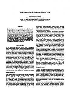
In order to implement the proposed data structure, three different motion generation approaches have been considered. Two of them, direct kinematics (DK) and inverse kinematics (IK), are related to motion modeling and the
other to motion replication (motion capture). Fig. 7 shows the three different procedures that the user may go through to transform a high level order such as “walk quickly” into a series of rendered frames. Subsequently, the two implementations’ examples are presented.
6.1 ARTGRAPH ARTgraph is a Development Environment devoted to the creation of high-quality real-time 3D-graphics applications: VR applications, 3D games, etc. It has been developed in the context of a European ESPRIT project [32]. The way to work with ARTgraph can be described through the following production chain: Graphic designers use standard modeling tools like Maya or 3D Studio to create a series of complex 3D objects which will populate the target 3D application. Application developers then import the 3D models created in order to modify their geometric data structure and add a series of execution-oriented data: polygon reduction, direct vertex manipulation, building of the scene hierarchy, and generation of real-time motion. Finally, developers can save both ARTgraph’s file format for use in the target application with ARTgraph’s execution libraries or standard formats like VRML. Several advanced character-animation techniques have been implemented as real-time features in ARTgraph’s runtime libraries: .
Keyframing that allows the introduction of motioncaptured data; our data structure is especially well
SERON ET AL.: ADDING SUPPORT FOR HIGH-LEVEL SKELETAL ANIMATION
369
Fig. 8. Manipulation of synthetic actor using IK (left) and DK (right). Note the IK manipulators used to position the effector and the DK manipulators used to position the dof’s.
Fig. 9. Some snapshots from ARTgraph.
fitted to rotational data file formats such as Acclaim. Nevertheless, some manipulation is always necessary. . Direct kinematics that allow direct access to the degrees of freedom. . Inverse kinematics: An IK module optimized for real-time has been developed. This module makes use of the direct access to the skeletons and the degrees of freedom provided by the two aforementioned actor’s lists. It allows defining, refining (number of iterations, skeleton joint and dof weights, constraints, etc.), and saving of different IK chains that can be used to position the actor in the scene. ARTgraph includes quick customizable 3D manipulators, which allow the developer to manipulate any parameter directly on the 3D actor. In Fig. 8, the IK and DK manipulators can be seen. Once defined, these parameters are accessed by the target application in real-time by means of the functions provided in ARTgraph’s runtime libraries. As we have seen, this access is provided directly via the
actor node so that the complexity of the underlying skeleton hierarchy remains hidden. In Fig. 9, different motions generated within ARTGraph application are presented.
6.2 ALVW The ALVW system is a general platform which provides and coordinates a sensing-analysis-acting loop to provide behavior for synthetic actors in their own scenario. ALVW [33] allows the user to design an environment, composed of special elements, dynamic and static objects, as well as possible inhabitants. Inhabitants are designed and controlled through a perception-analysis-reaction agent (based on a Fuzzy Expert System and on an Action Selection Mechanism), providing an autonomous and adaptive behavior. In the environment, special elements are controlled through a special pseudoagent based on genetic algorithms. Dynamic objects are animated using procedural motion and both types of objects provide time-varying attributes.
370
IEEE TRANSACTIONS ON VISUALIZATION AND COMPUTER GRAPHICS,
Fig. 10. Steps needed to produce 3D computer animation using Kukasim.
Fig. 11. Some snapshots of the 3D animation obtained using the data extracted from the simulator.
VOL. 8,
NO. 4,
OCTOBER-DECEMBER 2002
SERON ET AL.: ADDING SUPPORT FOR HIGH-LEVEL SKELETAL ANIMATION
The ALVW system has been used to model the behavior of cockroaches. The simulator Kukasim allows the user to define an environment (cockroach’s habitat) to design inhabitants (cockroaches) who sense, think, and react in this environment. The use of the simulator enables the user either to follow the evolution of the artificial ecosystem or to use the 3D data stored during a simulation to automatically produce a computer animation. Fig. 10 shows the process of producing a 3D animation from stored data generated by the simulator. On the left of the figure, the simulator is running and any relevant change of the state of the virtual ecosystem is stored on disk. Once a simulation is over, these data are integrated with a complete 3D geometric, visual, and motion modeling of the cockroaches and with their environment, as shown in the middle of Fig. 10. The result is a 3D computer animation, as seen to the right side of Fig. 10. The skeleton of the cockroach has been designed with an actor node and different skeleton nodes in order to obtain a convenient data structure for the process of motion generation, which is provided by using direct and inverse kinematics and based on biological gaits of a real cockroach. The path of the trajectory comes from the 3D stored data. Fig. 11 shows some snapshots of a computer animation obtained using the described method. The cockroach is wandering through the kitchen; suddenly, it smells some food and tries to reach it; on the way, it has to avoid an obstacle. In summary, this is an example of how to integrate behavior modeling with motion replication, using the data structure explained in previous sections for the latter.
371
[2]
[3]
[4]
[5]
[6]
[7]
[8]
[9]
[10] [11] [12]
[13]
[14]
[15]
7
DISCUSSION
The main contribution of this paper is to propose two new types of nodes specially designed to move real-time synthetic actors and to integrate them easily within any animation system. They have already been integrated using Performer1 in a specific scene graph, named ARTGRAPH, and in the ALVW system. However, they have been designed to be integrated easily inside any scene graph. The use of similar structures should contribute to facilitating and increasing the number of real-time computer graphics applications using actors which, due to the lack of this kind of actors’ representations, is very limited nowadays. This is the way in which this research wishes to contribute to the standardization process of multiplatform synthetic actors programs or libraries.
[16]
ACKNOWLEDGMENTS
[23]
The authors would like to thank David Roman for his hard work using Performer1. The CICYT- Ministry of Education & Science of Spanish Government has partly funded this project (TIC 98-0973-C03-02).
[17] [18] [19]
[20]
[21] [22]
[24]
[25] [26]
REFERENCES [1]
D. Thalmann and N. Magnenat Thalmann, “Computer Animation,” ACM Computing Surveys, vol. 28, no. 1, pp. 161-163, 1996.
[27]
M. Cavazza, R. Earnshaw, N. Magnenat-Thalmann, and D. Thalmann, “Motion Control of Virtual Humans,” IEEE Computer Graphics & Applications, vol. 18, no. 5, pp. 24-31, Sept./Oct. 1998. D. Thalmann, “A New Generation of Synthetic Actors: The RealTime and Interactive Perceptive Actors,” Proc. Pacific Graphics ’96, pp. 200-219, 1996. A. Pina, E. Cerezo, and F.J. Sero´n, “Computer Animation: From Avatars to Unrestricted Autonomous Actors (a Survey on Replication and Modelling Mechanisms),” Computers & Graphics, vol. 24, no. 2, section “Surveys,” pp. 297-311, 2000. C.W. Reynolds, “Flocks, Herds and Schools: A Distributed Behavioral Model,” ACM Computer Graphics, vol. 21, no. 4, pp. 25-34, 1987. M. McKenna, S. Pieper, and D. Zeltzer, “Control of a Virtual Actor: The Roach,” Proc. 1990 Symp. Interactive 3D Graphics, Computer Graphics, vol. 24, no. 2, pp. 165-174, 1990. S. Mah, T.W. Calvert, and W. Havens, “A Constraint-Based Reasoning Framework for Behavioural Animation,” Computer Graphics Forum, vol. 13, no. 5, pp. 315-324, 1994. C. Beardon and V. Ye, “Using Behavioural Rules in Animation,” Computer Graphics: Developments in Virtual Environments, R.A. Earnshaw and J.A. Vince, eds., pp. 217-234, London: Academic Press, 1995. J. Cremer, J. Kearney, and H. Ko, “Simulation and Scenario Support for Virtual Environments,” Computer & Graphics, vol. 20, no. 2, pp. 199-206, 1996. R.D. Beer, Intelligence as Adaptative Behaviour. Academic Press Ltd, 1990. P. Maes, “Modeling Adaptive Autonomous Agents,” Artificial Intelligence, vol. 1, nos. 1/2, pp. 135-162, 1994. X. Tu and D. Terzopoulos, “Artificial Fishes: Physics, Locomotion, Perception, Behavior,” Computer Graphics Proc., SIGGRAPH ’94, pp. 42-48, 1994. B.M. Blumberg and T.A. Galyean, “Multi-Level Control for Animated Autonomous Agents: Do the Right Thing...Oh, Not That,” Creating Personalities for Synthetic Actors, R. Trappl and P. Petta, eds., Springer-Verlag, pp. 74-82, 1997. H. Noser, L.S. Pandzic, T.K. Capin, N. Magnenat Thalmann, and D. Thalmann, “Playing Games through the Virtual Life Network,” Proc. Artificial Life V, 1996. D. Thalmann, “A New Generation of Synthetic Actors: The RealTime and Interactive Perceptive Actors,” Proc. Pacific Graphics ’96, 1996. N.I. Badler, B.D. Reich, and B.L. Webber, “Towards Personalities for Animated Agents with Reactive and Planning Behaviours,” Creating Personalities for Synthetic Actors, R. Trappl and P. Petta, eds., pp. 43-57, Springer-Verlag, 1997. D. Terzopoulos, “Artificial Life for Computer Graphics,” Comm. ACM, vol. 42, no. 8, pp. 33-42, 1999. J. Funge, “Cognitive Modelling for Games and Animation,” Comm. ACM, vol. 43, no. 7, pp. 40-48, 2000. D.E. Goldberg, “IMPROV: A System for Real-Time Animation of Behaviour-Based Interactive Synthetic Actors,” Creating Personalities for Synthetic Actors, R. Trappl and P. Petta, eds., pp. 58-73, Springer-Verlag, 1997. B. Hayes-Roth, R. Van Gent, and D. Huber, “Acting in Character,” Creating Personalities for Synthetic Actors, R. Trappl and P. Petta, eds., pp. 92-112, Springer-Verlag, 1997. J. Bates, “The Role of Emotion in Believable Agents,” Comm. ACM, vol. 37, no. 7, pp. 122-125, 1994. W. Bethel, C. Bass, S. Rose, B. Hook, M. Jones, H. Sowizral, and A. van Dam, “Scene Graph: Wired or Tired?” Conf. Abstracts and Applications, Computer Graphics Ann. Conf. Series, ACM SIGGRAPH, pp. 136-138, 1999. J. Wernecke, The Inventor Mentor: Programming Object-Oriented 3D Graphics with Open Inventor, Release 2. Addison-Wesley, 1994. J. Rohlf and J. Helman, “Iris Performer: A High Performance Multiprocessing Toolkit for Real-Time 3D Graphics,” SIGGRAPH ’94 Computer Graphics Proc. Ann. Conf. Series, pp. 381-394, 1994. SGI’s OpenGL Optimizer’s white paper at: http://www.sgi.com/ software/optimizer/whitepaper.html, 1993. SUN’s Java3D API specification http://java.sun.com/products/ javamedia/3D/forDevelopers/ J3D_1_2_API/j3dguide/index. html, 2000. VRML 97 specifications http://www.web3d.org/Specifications/ VRML97/, 1997.
372
IEEE TRANSACTIONS ON VISUALIZATION AND COMPUTER GRAPHICS,
[28] RMscenegraph’s white paper at: http://www.r3vis.com/ RMSceneGraph/techref.html, 1999. [29] Human Animation Working Group, Specification for a Standard VRML Humanoid Version 1.1 available from http://h-anim.org, 1998. [30] R. Boulic, T. Capin, Z. Huang, P. Kalra, B. Lintermann, N. Magnenat-Thalmann, L. Moccozet, T. Molet, I. Pandzic, K. Saar, A. Schmitt, J. Shen, and D. Thalmann, “The Humanoid Environment for Interactive Animation of Multiple Deformable Human Characters,” Proc. Eurographics ’95, Computer Graphics Forum, vol. 14, no. 3, pp. 337-348, 1995. [31] MPEG-4 Body Model proposal, MPEG-4 SNCH (Synthetic/ Natural Hybrid Coding), http://ligww.epfl.ch/mpeg4/, 1999. [32] “ARTIST: Animation Package for Real-Time Simulation,”ESPRIT Project E20102, developed by LISITT (Univ. of Valencia, Spain), GIGA (Univ. of Zaragoza, Spain), Norks Regnesentral (Norway), APD (Spain), and ART&Magic (Belgium), 1997. [33] A. Pina and F.J. Sero´n, “Behaviour Modelling, Computer Animation and Ecology,” IASTED CGIM 2000, Int’l Conf. Computer Graphics and Imaging, pp. 313-318, 2000. Francisco J. Seron received the Physical Science degree from the University of Zaragoza in 1977 and the PhD degree from the same University in 1984. He is an associate professor of computer science at the Technical School of Engineering at the University of Zaragoza. At present, he is the head of the Advanced Computer Graphics Group within the Computer Science Department. His research interests include simulation of natural phenomena, illumination engineering, and virtual reality. He is a member of the IEEE.
Rafael Rodriguez received the BS and MS degrees from the University of Alcala´ de Henares and the Polytechnic University of Valencia. He is a PhD candidate in computer science at the University of Valencia, Spain. His research interests are real-time computer graphics and virtual actors. Currently, he is a member of the research staff of Brainstorm Multimedia and he is preparing his PhD thesis on the integration of virtual actors in simulation applications.
VOL. 8,
NO. 4,
OCTOBER-DECEMBER 2002
Eva Cerezo obtained the BS degree in physics in 1990 and the MsC degree in nuclear physics from the University of Zaragoza in 1992. She received the PhD degree in computer science in 2002. She is an associated lecturer at the University of Zaragoza, Spain and a member of the Advanced Computer Graphics Group. Her research interests include physically based modeling, medical imaging and simulation of natural phenomena.
Alfredo Pina has been an associated lecturer at the Public University of Navarra, Pamplona, Spain, since 1991. He has received the computer science PhD degree from the University of Zaragoza in 2001, the BS degree in computer science from Bordeaux University, France, in 1986, and the MsC degree in KBS from HeriotWatt University, Scotland, in 1989. He is actually a collaborator of the GIGA group (Advanced Computer Graphics) at the University of Zaragoza, Spain. His research interests include artificial life, artificial intelligence, and behavior modeling for computer animation.
. For more information on this or any computing topic, please visit our Digital Library at http://computer.org/publications/dlib.